3 Sensor Specifications
3.1 Start With the Measurement Story
A datasheet number looks precise until the device leaves the lab. Start with the field claim: what range, resolution, accuracy, latency, and operating conditions must hold before a reading can drive an IoT decision?
3.2 Specifications Need Conditions
Sensor specifications describe what a sensor can measure, how fine its output can be, how close readings may be to the true condition, how repeatable the readings are, and which conditions must be true for those claims to hold. They are not marketing labels. They are evidence claims that need units, limits, operating conditions, calibration context, and test records.
The first review habit is to separate the physical measurement from the displayed number. A sensor can report many decimal places and still be inaccurate. A sensor can be repeatable and still be biased. A sensor can work well in the lab and fail in the field because mounting, moisture, vibration, temperature, aging, or power mode changed the conditions.
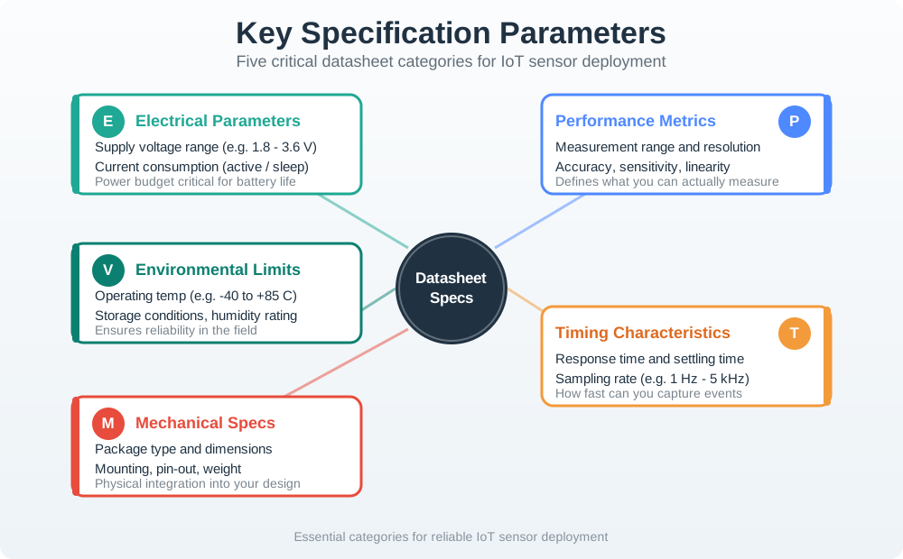
Read those categories together, not as independent badges. A low-power sensor that fits the battery budget can still be wrong for the installation if its humidity limit is exceeded. A fast sensor can still be unusable if its package cannot be mounted where the physical condition actually occurs. A high-resolution sensor can still mislead a control rule if the accuracy and drift claims are weaker than the threshold being enforced.
A useful specification record therefore keeps the claim, condition, and evidence side by side. Write down the value being promised, the environment or calibration state where it applies, and the test or field observation that will prove it after installation. That habit turns the datasheet into an engineering decision record instead of a list of attractive numbers.
If you only need the core idea, use this rule: match sensor specifications to the decision the IoT system must make, then keep evidence that the sensor meets those specifications in the real installation.
The Core Specification Set
Measurement Fit
Range, span, operating conditions, and response time decide whether the sensor can observe the target condition where the device is installed.
Signal Quality
Resolution, sensitivity, noise, precision, hysteresis, and drift decide whether the reported change is meaningful or just measurement behavior.
Evidence
Accuracy, calibration records, reference checks, datasheet conditions, and field validation decide whether the reading can support an application decision.
Beginner Examples
- A temperature sensor with fine resolution can show small changes, but the reading is still limited by its accuracy and calibration evidence.
- A fast response time matters for alarms and control loops; slower response may be acceptable for trend logging.
- A wide operating range matters when the installation sees outdoor, refrigerated, heated, humid, or dusty conditions.
- A low unit price is not enough if the sensor drifts quickly, corrodes, or requires frequent field replacement.
For timing claims, distinguish response time from a simple time constant. Response time is the time needed for the output to settle inside a named tolerance band after the input changes; a rising step and a falling step can have different settle or decay times. An RC-like time constant is usually shorter than the final response-time specification, so an alarm or control record should name the tolerance band, step direction, and test condition.
Overview Knowledge Check
3.3 Specification Record
A practical sensor review starts with the application decision. What condition must be detected? What threshold, trend, alarm, or control action depends on the reading? Once the decision is clear, specifications become filters: reject sensors that cannot support the decision under field conditions, and avoid paying for performance the decision cannot use.
The record should be short, explicit, and testable. It names the measured condition, required range, required accuracy, acceptable response time, expected noise, calibration method, power mode, installation condition, and the evidence that proves the sensor is still valid after deployment.
How It Works: Read the Specification Chain
- Start with the decision. State the alarm, control action, trend, report, or diagnostic that depends on the measurement.
- Set the measurement envelope. Record the physical range, operating environment, response-time need, and mounting constraint.
- Separate accuracy, precision, and resolution. Ask which error is systematic, which variation is random, and which display step is merely output granularity.
- Check calibration and drift. Identify the reference, calibration interval, offset or scale factor, repeatability check, and review trigger.
- Close with evidence. Keep datasheet conditions, bench checks, installation notes, field validation readings, and exceptions that would force re-selection.
Specification Review Ledger
Intermediate Example
A greenhouse controller triggers irrigation from soil moisture readings. The selection record should not start with the cheapest part. It should state the irrigation threshold, soil type, installation depth, expected moisture range, acceptable uncertainty around the threshold, response-time need, corrosion risk, power budget, calibration method, and field-check schedule. A sensor that is inexpensive but drifts or fails after repeated wetting can be more expensive than a durable sensor once replacement visits are counted.
Practitioner Knowledge Check
3.4 Error Sources and Evidence Limits
Specifications are linked because every sensor is a measurement chain. The physical condition must reach the sensing element, the element must produce a signal, the circuit must condition it, the interface must transmit it, firmware must parse it, and the application must interpret it. A failure at any link can look like a sensor problem.
Under the hood, the strongest review separates uncertainty into categories. Offset and scale errors may be corrected by calibration. Random noise may need averaging, shielding, filtering, or different hardware. Hysteresis and drift may require replacement limits or regular reference checks. Response lag may require different placement, different sensing technology, or a slower control expectation.
Advanced Example
A cold-chain monitor needs more than a temperature value. The record should name the allowed storage window, sensor accuracy under that window, calibration reference, enclosure thermal lag, sampling interval, alarm rule, battery behavior at low temperature, data retention during connectivity loss, and evidence retained after a temperature excursion. A reading that appears valid on the dashboard is not enough if the sensor was mounted where it responds slowly to the product temperature.
Error-Boundary Checklist
- Offset: The sensor is consistently high or low; calibration may subtract the bias if the reference is valid.
- Scale: The output changes too much or too little across the span; calibration may need more than one point.
- Resolution: The output step is too coarse for the required change; software cannot invent missing measurement detail.
- Noise: Repeated readings vary under stable conditions; averaging can help only when the process can tolerate delay.
- Hysteresis: The reading depends on whether the condition approached from above or below; record direction-sensitive behavior.
- Drift: The same condition produces a different reading over time; define recheck, recalibration, or replacement triggers.
- Response lag: The reading trails the physical event; test whether the delay is acceptable for the decision.
Evidence That Makes a Specification Trustworthy
Datasheet Context
Record the exact conditions behind a specification, including supply range, temperature range, sampling mode, and calibration assumptions.
Bench Reference
Compare the sensor against a suitable reference before field deployment, then keep the raw readings and correction method.
Field Validation
Confirm mounting, airflow, moisture, vibration, shielding, cable length, enclosure behavior, and maintenance access in the real installation.
Review Trigger
Define what forces a recheck: drift, firmware change, new enclosure, replaced sensor, failed reference check, or unexplained alarm behavior.
Under-the-Hood Knowledge Check
3.5 Summary
Sensor specifications are conditions-backed claims. Range, operating conditions, response time, accuracy, precision, resolution, sensitivity, noise, hysteresis, drift, power, and calibration evidence all shape whether a reading can support an IoT decision.
The safest selection workflow starts with the application decision, then builds a specification record that can be tested in the real installation. A trustworthy record distinguishes resolution from accuracy, repeatability from correctness, bench behavior from field behavior, and unit price from lifetime cost.
3.6 Key Takeaway
Read sensor specifications as evidence boundaries. A reading is useful only when the sensor, signal path, calibration, installation, and field conditions all support the decision being made.
3.7 See Also
Sensor Introduction and Fundamentals
Use this for the broader measurement chain before reviewing individual specifications.
Common Sensors and MEMS
Compare common sensor families after the key specification terms are clear.
Sensor Selection Guide
Turn specification requirements into a defensible sensor choice for a deployment.
Sensor Calibration Techniques
Connect specification claims to reference checks, offsets, scale factors, drift, and evidence records.