Environmental Sensors
Temperature, humidity, pressure, air-quality, and light sensors support comfort, weather, storage, equipment, and environmental monitoring claims.
A smart-room prototype can sense motion, light, temperature, sound, gas, or orientation, but each family tells a different kind of story about the room. The design starts by naming the change that matters and the sensor family that can observe it reliably.

This chapter names the thermocouple’s Seebeck effect in one line and moves on, but it is the one common-sensor mechanism whose governing equation cannot be inverted from the sensor’s own output alone. A thermistor’s resistance depends only on its own temperature, so one reading is one answer. A thermocouple’s voltage depends on the difference between two junction temperatures – the hot junction where you actually want the measurement, and a cold (reference) junction wherever the sensing wire meets the copper of your measuring instrument. Read the voltage without also knowing the cold-junction temperature, and you can compute a \(\Delta T\), but not a \(T\). That is why every real thermocouple circuit either sits in ice water (impractical) or carries a second, ordinary temperature sensor at the cold junction to complete the inversion – a wide-temperature-span sensor that secretly depends on a second, narrow-span sensor to be useful at all.
The Seebeck effect produces a voltage proportional to the temperature difference between the two junctions:
\[V = S\,(T_{hot} - T_{cold})\]
where \(S\) is the Seebeck coefficient of the wire pair. Inverting for the quantity actually wanted, \(T_{hot}\), requires knowing the cold-junction temperature separately:
\[T_{hot} = \frac{V}{S} + T_{cold}\]
Common IoT sensors include temperature, humidity, pressure, light, motion, distance, position, current, gas, and contact sensors. MEMS devices add tiny mechanical structures for acceleration, rotation, pressure, microphones, and other compact measurements. These families are useful starting points, but a family name does not prove fit.
A sensor becomes acceptable when its measured quantity, operating principle, output form, range, response time, calibration need, interface, power behavior, environmental limit, and failure mode match the application decision. A familiar module can still be wrong if it cannot preserve the evidence the system needs.
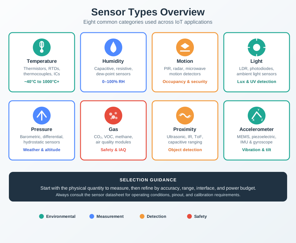
The same family can hide very different evidence burdens. A temperature reading might come from a thermistor, RTD, thermocouple, or digital IC. A motion claim might come from PIR detection, radar presence, a MEMS accelerometer, or a camera pipeline. Those options can all look familiar on a parts list while carrying different mounting, firmware, privacy, calibration, and maintenance requirements.
For that reason, treat common families as comparison bins rather than answers. First decide what the system must prove, then narrow the family by the physical coupling, signal path, interface, power state, and failure behavior that match the installed device.
If you only need the intuition, use this rule: choose a common sensor by the decision it must support, not by popularity. Name the physical quantity, evidence limit, interface, calibration burden, and retest trigger.
Temperature, humidity, pressure, air-quality, and light sensors support comfort, weather, storage, equipment, and environmental monitoring claims.
PIR, accelerometers, gyroscopes, magnetometers, encoders, and proximity sensors support occupancy, movement, tilt, vibration, rotation, and position claims.
Ultrasonic, optical time-of-flight, radar, and similar devices emit energy, so review power, target surface, field of view, interference, and safety limits.
Datasheet values, module defaults, library examples, and bench demos must be checked against mounting, enclosure, calibration, aging, and field conditions.
A useful comparison record keeps the design from overfitting to a familiar module. It names candidate sensor families, the evidence each can preserve, what each cannot prove, and which field change would force a retest. The record should be short enough to use during procurement and specific enough to survive maintenance.
Environmental families are a good place to make the comparison concrete. For light, separate the photometric unit from the sensing element: candela describes luminous intensity, lumens describe total visible light emitted by a source, and lux describes illuminance falling on a surface. An LDR or photoresistor changes resistance with light and is useful for simple threshold or daylight-trend decisions. A photodiode produces photocurrent and is better when response speed and linear readout matter. A phototransistor adds gain, so it can be sensitive in simple circuits, but it trades off linearity, saturation behaviour, and low-light performance.
For temperature, a thermocouple uses the Seebeck effect and survives very wide temperature spans, an NTC thermistor is cheap and sensitive in a narrower range, and an RTD is more linear and stable when the budget supports the front end. For relative humidity, capacitive, resistive, and thermal devices all report moisture by a different physical effect; their useful record should include response time, hysteresis, long-term stability, condensation exposure, and temperature compensation. These concrete family names help procurement, but the acceptance still depends on the same evidence: range, accuracy, calibration, placement, interface, power state, and retest trigger.
The mechanism matters. A capacitive humidity sensor changes capacitance as a moisture-sensitive dielectric absorbs water. A resistive humidity sensor changes resistance through a salt, polymer, or other conductive medium as moisture content changes. A thermal-conductivity humidity sensor compares heat loss from protected and exposed thermal elements, so airflow, temperature compensation, and contamination can dominate its evidence. The record should say which mechanism is installed before assuming that one humidity module can stand in for another.
MEMS sensors deserve the same treatment. An accelerometer, gyroscope, pressure sensor, or microphone may be compact and low power, but the evidence still depends on mounting, orientation, noise, temperature behavior, packaging, sampling, and signal processing.
Most sensor-family failures happen at the boundary between the physical world and the digital record. The transducer may be right for the category but wrong for the mounting. The output may be digital but calibrated poorly. The reading may be stable but biased by enclosure heat, airflow, sunlight, vibration, humidity, power state, or target material.
MEMS devices make this boundary easy to miss because the sensing structure, analog front end, ADC, and compensation logic often sit inside one small package. The package may output a clean acceleration, rotation, pressure, or microphone value, but the proof mass, diaphragm, or resonant structure still reacts to stress, temperature, orientation, shock, vibration, and board mounting. Treat the package output as interpreted evidence, not raw truth.
Resistance, capacitance, optical reflection, acoustic timing, pressure, magnetic field, chemical response, and MEMS motion each have different interference paths.
Analog outputs, pulse timing, threshold pins, and digital buses need different evidence for noise, timing, reference voltage, parsing, and error state.
Passive sensors observe existing conditions; active sensors emit, heat, illuminate, ping, or process, so duty cycle and recovery behavior matter.
Sensor age, contamination, drift, recalibration, firmware changes, replacement parts, and support ownership determine whether evidence remains valid.
Selection should also protect against false precision. A module may produce a number with many decimal places even when accuracy, placement, or calibration does not support that level of trust. A binary output may look decisive even when the threshold, delay, warm-up, or false-trigger behavior is poorly understood.
The under-the-hood rule is to ask what can make the common sensor lie. If that failure mode would change the application decision, it belongs in the selection record with a diagnostic, fallback, known limit, or retest trigger.
That question should include software boundaries too. Library defaults can hide averaging windows, unit conversions, compensation tables, debounce rules, and invalid-state handling. When those defaults change, the sensor family has not changed, but the evidence path has.
Choose common sensors by evidence fit. The accepted record should tie measured quantity, operating principle, interface, calibration, environment, known limit, owner, and retest trigger to the IoT decision.
Classify sensors by measured quantity, signal form, power behavior, and evidence limits before comparing specific families.
Interpret range, accuracy, resolution, response time, drift, noise, and calibration claims before accepting a device.
Trace datasheet conditions, interface details, operating limits, and test assumptions for a chosen part.
Turn family comparison into a practical selection record with tradeoffs, rejection reasons, and retest triggers.