10 Resistive Dividers and ADC Loading
10.1 Start With the Measurement Story
A resistive sensor only becomes useful when its changing resistance becomes a measurable voltage. The story is the divider, the ADC input, the loading error, and the evidence that the chosen values still leave enough resolution.

Phoebe’s Why
An ADC never reports a continuous voltage; it reports one of \(2^N\) discrete codes, so any two thermistor resistances close enough to land in the same bin are, to firmware, identical. That rounding is a physical noise floor, not a bug – spread uniformly across one code step, its RMS size is a fixed fraction of that step, \(q/\sqrt{12}\). Because this chapter’s divider maps resistance onto voltage through a ratio, not a straight line, that quantization floor does not translate into the same number of ohms everywhere on the curve; it translates into fewer ohms exactly where the divider is already least sensitive.
The Derivation
The ADC’s quantization step and its noise-floor equivalent:
\[q = \frac{V_{ref}}{2^N}, \qquad e_{rms} = \frac{q}{\sqrt{12}}, \qquad \mathrm{SNR} = 6.02N + 1.76\ \text{dB}\]
The chapter’s own divider, \(V_{out}=V_s R_b/(R_t+R_b)\), has a local sensitivity found from the quotient rule:
\[\frac{dV_{out}}{dR_b} = \frac{V_s R_t}{(R_t+R_b)^2}\]
so the smallest resistance change the ADC can resolve at a given operating point is the quantization step divided by that local sensitivity:
\[\Delta R_{min} = \frac{q}{dV_{out}/dR_b}\]
Worked Numbers: This Chapter’s Own 10 k\(\Omega\)/10 k\(\Omega\) Divider
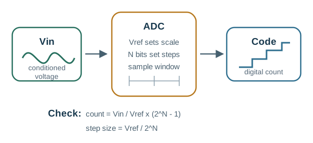
- Quantization step (this chapter’s own 12-bit ADC on the 3.3 V rail): \(q = 3.3/4096 = 8.057\times10^{-4}\) V \(= 0.806\) mV; \(\mathrm{SNR} = 6.02(12)+1.76 = 74.0\) dB
- At the 25 °C balance point (\(R_t=R_b=10\ \mathrm{k}\Omega\)): \(dV_{out}/dR_b = 3.3\times10^4/(2\times10^4)^2 = 82.5\ \mu\text{V}/\Omega\), so \(\Delta R_{min} = 0.806/0.0825 \approx 9.77\ \Omega\) per code
- At the chapter’s own warmer point (\(R_b=4.0\ \mathrm{k}\Omega\)): \(dV_{out}/dR_b = 3.3\times10^4/(1.4\times10^4)^2 = 168\ \mu\text{V}/\Omega\), so \(\Delta R_{min} = 0.806/0.168 \approx 4.79\ \Omega\) per code – the same ADC resolves thermistor resistance nearly twice as finely here as it does at balance
- The takeaway: the 878-count separation this chapter already reports between the 25 °C reading (2048 counts) and the 4.0 k\(\Omega\) warm reading (1170 counts) is nowhere close to this quantization floor, so the threshold design is safe; a design chasing a much smaller resistance swing on the same divider would need to check this floor before trusting the count
10.2 Learning Objectives
After this page, you should be able to:
- Explain how thermistors, LDRs, FSRs, and potentiometers convert physical changes into resistance changes.
- Use voltage-divider math to convert resistance into an ADC-readable voltage.
- Apply the ratiometric trick so supply drift cancels from ADC codes.
- Choose divider values that balance sensitivity, battery current, and ADC source-impedance limits.
- Diagnose ADC loading when high-value dividers under-charge the sample-and-hold capacitor.
10.3 After Sensor Circuit Basics
Sensor Circuit Fundamentals introduces voltage dividers, filters, switches, and LED protection as reusable blocks. This page focuses on the analog-input details that decide whether a divider reading is trustworthy after it reaches the ADC.
Use it when a thermistor, LDR, FSR, or potentiometer circuit works on a multimeter but reads differently in firmware. The likely causes are reference mismatch, poor fixed-resistor choice, high source impedance, short sample time, or a missing buffer capacitor or op-amp buffer.
10.4 Resistance to Readable Voltage
A large family of sensors are, electrically, just variable resistors. A thermistor's resistance falls as it warms; a photoresistor (LDR) drops as light increases; a force-sensitive resistor (FSR) drops under pressure; a potentiometer's wiper resistance tracks an angle. This is resistive transduction: the physical quantity changes a resistance.
The underlying physics can be summarized as R = rho * l / A: resistance rises with conductor length l, falls with cross-sectional area A, and changes when the material's resistivity rho changes. That distinction helps classify real resistive sensors. A strain gauge changes shape as the foil stretches, so l and A move slightly. A thermistor or resistive moisture probe mainly changes effective rho as temperature, water content, ions, or contact conditions change. The firmware still sees one problem: turn that resistance change into a voltage or bridge output that preserves enough margin to make the decision.
The problem is that a microcontroller's ADC measures voltage, not resistance. It has no direct way to read ohms. The bridge between them is the most common sensor circuit in embedded systems: the voltage divider, which pairs the sensing resistor with a fixed reference resistor so that a change in resistance becomes a change in voltage at their junction.
Worked example. Put a 10 kΩ fixed resistor on top, a 10 kΩ thermistor on the bottom, and power the divider from 3.3 V. At 25 °C the junction is 3.3 * 10k / (10k + 10k) = 1.65 V. A 12-bit ADC using the same 3.3 V rail reads about 1.65 / 3.3 * 4095 = 2048. If the thermistor warms to 5 kΩ, the junction becomes 3.3 * 5k / (10k + 5k) = 1.10 V, or about 1365 counts. Firmware does not need to know resistance directly; it watches the count move from roughly 2048 toward 1365 and maps that movement to temperature after calibration.
That count movement is also what makes simple decisions reliable. If a fan should turn on above the warm point, a threshold around 1500 counts leaves about 2048 - 1500 = 548 counts of margin from the 25 °C reading and 1500 - 1365 = 135 counts from the warm reading. The circuit turns a physical change into numeric separation that software can test.
Intuition: two resistors in series across a supply split the voltage in proportion to their sizes. Make one of them the sensor, and the split point moves as the physical world changes. The ADC watches that moving split point.
Overview Knowledge Check
10.5 Divider Math and Ratiometric ADC
For two resistors in series from supply Vs to ground, with the ADC tapping their junction, the output voltage is:
Vout = Vs × Rbottom / (Rtop + Rbottom)
Worked example: 10 kΩ NTC thermistor divider at 3.3 V
Put a 10 kΩ fixed resistor as Rtop and a 10 kΩ NTC thermistor as Rbottom, supplied from 3.3 V:
At 25 °C the NTC is 10 kΩ:
  Vout = 3.3 × 10k / (10k + 10k) = 1.65 V

The NTC is negative-tempco, so as it warms its
resistance falls. Say at ~50 °C it reads 4.0 kΩ:
  Vout = 3.3 × 4.0k / (10k + 4.0k) = 0.943 V

Warmer -> lower NTC resistance -> lower Vout.
Swap the two resistors (thermistor on top) and the direction reverses: warmer would raise Vout. Choosing which leg is the sensor sets the sign of your reading.
Now translate those voltages into ADC counts. With a 12-bit converter referenced to the same 3.3 V rail, 1.65 V is about 2048 counts and 0.943 V is about 1170 counts, a separation of 878 counts. That is large enough for a simple threshold or lookup table. If the supply droops to 3.1 V and the ADC reference droops with it, both voltages shrink but the code ratio stays the same. If the divider uses 3.3 V while the ADC uses a separate drifting reference, the same physical temperature can produce a different code, so calibration no longer transfers cleanly.
The ratiometric trick: if you feed the divider from the same reference that the ADC uses (Vref = Vs), then code = 2^N × Rbottom/(Rtop+Rbottom). The supply value cancels out. The reading depends only on the resistance ratio, so it is immune to supply drift and ripple — a free and widely used robustness win.
Practitioner Knowledge Check
10.6 Divider Sensitivity and ADC Load
Two second-order effects decide whether a divider that works on paper works on the bench.
Sensitivity is not uniform
The output moves most per ohm when the two resistors are comparable. Choosing the fixed resistor near the sensor's resistance at the operating point you care about places the divider in its most sensitive, most linear region there.
The divider is inherently nonlinear
Because resistance sits in the denominator, equal resistance steps do not give equal voltage steps. Over a wide range the response curves, so firmware still needs a calibration or linearization step, not just Ohm's law.
ADC loading and source impedance
The ADC's sample-and-hold capacitor must charge through the divider's output impedance during the sample window. If the legs are very high (hundreds of kΩ), the cap under-charges and readings come out low.
Fixes for high impedance
Keep the source impedance under the ADC's recommended limit (often around 10 kΩ), lengthen the sample time, add a small buffer capacitor at the ADC pin, or drive the ADC through a unity-gain op-amp buffer.
Impedance is a genuine trade-off. Low-value legs load the ADC lightly and settle fast, but they draw continuous current through the divider — wasteful on a battery node. High-value legs sip almost no current but fight the ADC's input capacitance. The sweet spot balances power against settling.
Worked example. The ADC sees the divider through its Thevenin output resistance, Rtop || Rbottom. Two 220 kΩ legs look like 110 kΩ at the ADC pin. If the sample capacitor is about 5 pF, the charging time constant is 110k * 5pF = 0.55 us. A 12-bit conversion needs roughly nine time constants to settle near half an LSB, so the sample window should be on the order of 9 * 0.55 = 5 us or more. If the ADC samples for only about 1 us, the capacitor has not reached the true divider voltage and the code reads low. Change the divider to 10 kΩ legs and the source resistance becomes 5 kΩ; now tau = 25 ns and nine time constants are only 225 ns.
Under-the-Hood Knowledge Check
10.7 Release Checklist
Before relying on a resistive sensor divider, confirm these points:
- Divider orientation is documented so firmware knows which direction the reading moves.
- The fixed resistor is near the sensor resistance at the operating point that matters most.
- Divider supply and ADC reference are shared when ratiometric cancellation is expected.
- Divider Thevenin resistance is within the ADC source-impedance guidance or sample time is lengthened.
- Battery-current cost is acceptable, or the divider is duty-cycled with enough settle time.
10.8 See Also
- Sensor Circuit Fundamentals for the broader circuit block overview.
- Signal Conditioning for filtering, amplification, bridges, and protection.
- Sensor Data Processing for filtering and calibration after acquisition.
- Accuracy, Precision, Drift, and Hysteresis for reporting the remaining measurement uncertainty.
10.9 Next
Return to Sensor Circuit Fundamentals once the divider and ADC boundary are verified, then continue to Signal Conditioning for amplification and filtering chains.