4 Your First Bench Build
A first-bench workflow for safe wiring, bring-up, measurement, and repeatable records
hardware prototyping getting started, first hardware prototype, breadboard workflow, safe power checks, prototype bring-up, hardware measurement record

Phoebe’s Why
This chapter’s two first-bench parts, an LED plus resistor and an LDR divider on an ADC pin, are both Ohm’s law wearing different clothes. The LED resistor exists because an LED is not itself current-limiting: without a series resistor, a 3.3 V rail would try to force far more current through the diode than its junction can survive, so the resistor sets the current the rest of the circuit allows. The LDR divider is the same law read a different way: light changes the LDR’s resistance, and a fixed resistor below it converts that resistance change into a voltage the ADC can actually read. Neither component reports light or current directly – the divider reports a voltage ratio, and it is the firmware’s job to know that ratio is not linear in light level.
The Derivation
Ohm’s law sets the LED series resistor from the rail voltage \(V_S\), the diode’s forward drop \(V_f\), and the target current \(I\):
\[R = \frac{V_S - V_f}{I}\]
A resistive-divider sensor (the LDR) splits the same rail between a fixed resistor \(R_1\) and the sensor’s own resistance \(R_{sensor}\):
\[V_{out} = V_S\,\frac{R_1}{R_1 + R_{sensor}}\]
That output only equals half the rail when the sensor matches the fixed resistor, \(R_{sensor}=R_1\) – everywhere else the transfer is a curve, not a line, which is why the “raw reading” this chapter asks you to record is a voltage ratio, not a light level.
Worked Numbers: This Chapter’s 3.3 V Rail
Using the 3.3 V rail this chapter names repeatedly, with catalog-typical part values it does not specify:
- LED resistor (red LED, \(V_f=2.0\) V, target \(I=10\) mA): \(R = (3.3-2.0)/0.010 = 130\ \Omega\)
- LDR divider (catalog-typical photoresistor, \(R_1=10\ \text{k}\Omega\) fixed): bright room (\(R_{sensor}\approx8\ \text{k}\Omega\)) gives \(V_{out}=3.3\times10/(10+8)=1.83\) V; dark (\(R_{sensor}\approx1\ \text{M}\Omega\)) gives \(V_{out}=3.3\times10/(10+1000)=0.0327\) V
- On a 12-bit ADC (\(V_{ref}=3.3\) V, codes \(0\)-\(4095\)): bright reads code \(2275\), dark reads code \(41\) – most of the ADC’s range is spent on a fairly narrow slice of everyday light levels, because the divider’s response compresses hard once \(R_{sensor}\) grows past \(R_1\)
That compression is exactly why the “first input” proof step should record the raw code alongside the lighting condition, not just “sensor works”: a threshold set from one lighting condition can sit on the flattest part of this curve and barely move for a real change in brightness.
4.1 Start With the Story
The first bench build often fails for ordinary reasons: a jumper is in the wrong rail, a sensor has no ground reference, a board package is stale, or the supply current limit is set too low. A novice sees a broken project. A good prototyper sees a sequence to make the failure visible without guessing.
Start this chapter with one safe circuit and one observable result. Power first, signal second, firmware third, notes throughout. When the bench record is clear enough for another person to repeat, the prototype has become evidence instead of a private memory.
4.2 First Build as Experiment
Your first bench build should answer one small question safely: can this board power up, run known firmware, read one input, drive one output, and leave a record someone else can repeat?
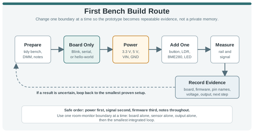
The reliable path is board first, power second, one external part third. A room-monitor demo, button-and-LED test, or sensor-readout sketch should never start with every wire, library, and enclosure choice changing at once.
- Prove the board alone before external components can be blamed for upload, USB cable, boot mode, or serial-port failures.
- Measure the rail before and after each new part so a load, reversed sensor, or short is caught early.
- Keep the record small but include board name, firmware file, pin names, measured voltage, observed output, and next step.
For example, a first room-monitor build with an Arduino Uno R4 WiFi, Raspberry Pi Pico W, ESP32 DevKit, or Adafruit Feather should begin with the board by itself. Upload Blink, a serial heartbeat, a CircuitPython print loop, a MicroPython script, or an ESP-IDF hello-world example and write down the board target, USB port, tool version, and observed output. If that baseline fails, the next useful action is not wiring a BME280, relay board, or OLED display. It is checking the cable, boot mode, driver, board package, and power state while the setup is still simple.
After the baseline works, add one boundary. A beginner temperature indicator might add only a BME280 on I2C, measure the 3.3 V rail before and after wiring, scan or log the detected address, and print one raw reading. The next build might add an LED through a resistor or a MOSFET input for a low-current indicator. The point is to leave a trail of working states: board alone, sensor alone, output alone, then the smallest integrated loop. When the final loop fails, you know which boundary changed last.
4.3 Bring Up One Boundary at a Time
A useful beginner bench can be simple: a development board, breadboard, jumper wires, resistors, USB cable, digital multimeter, and, when available, a current-limited bench supply. The discipline is in the sequence, not the price of the tools.
- Board baseline: upload Blink, a serial heartbeat, CircuitPython REPL print, MicroPython script, Arduino sketch, PlatformIO project, ESP-IDF hello-world, or Zephyr sample before wiring a sensor.
- Power check: identify 3.3 V, 5 V, VIN, GND, EN, RESET, and battery pins; measure with a DMM; avoid treating GPIO pins as load supplies.
- First input: test a button with pull-up or pull-down, an LDR divider, a potentiometer on an ADC pin, or an I2C sensor such as BME280 or SHT31 by itself.
- First output: start with an LED plus resistor, small buzzer, display message, or driver input; use a transistor, MOSFET, relay module, or motor driver before switching real loads.
A practical first-bench log should be boring and specific. Start with the date, board model, power source, current limit if a bench supply is used, firmware file, toolchain, and the exact stop condition. Before applying power to a breadboard circuit, use continuity mode to check that supply and ground are not shorted. Then power the board and measure the rail at the board header and at the breadboard rail. A USB-powered Pico W or ESP32 board may look fine at the USB connector while a loose jumper leaves the sensor rail unpowered. Measuring both places prevents that mistake from becoming a library problem.
Choose tools for the symptom. A digital multimeter can prove polarity, voltage, continuity, and a missing ground. A serial monitor can prove firmware identity and show whether the loop is running. A Saleae Logic, Bus Pirate, or sigrok/PulseView capture can show whether I2C SCL and SDA are moving and whether the sensor NACKs its address. A current-limited bench supply can keep a wiring mistake from damaging a regulator. Beginners do not need all of these at once, but they should understand what each tool can and cannot see.
4.4 First Failures Hit Boundaries
Beginner hardware failures often happen at boundaries: USB to board, board to breadboard, GPIO to load, 3.3 V logic to 5 V module, firmware pin name to package pin, or I2C address to library setting.
- Electrical boundary: check voltage domain, current draw, polarity, shared ground, current-limiting resistor, flyback diode, and pull-up or pull-down path.
- Firmware boundary: record board target, port, baud rate, bootloader mode, library version, pin constant, firmware hash, and serial output timing.
- Breadboard boundary: confirm row breaks, rail splits, jumper continuity, component orientation, and whether the supply rail is connected on both sides.
- Debug boundary: return to the known-good firmware and board-only measurement whenever a new symptom appears after adding a wire, module, or library.
That habit turns a first build from a pile of parts into a repeatable engineering setup.
Many early faults are caused by two names for the same physical point not being checked against each other. A tutorial may say D2, a board silkscreen may say GP2, a microcontroller data sheet may name the package pin differently, and a framework may expose the pin as GPIO2 or a board-specific constant. A breadboard adds another mapping layer because the power rails may be split and the rows are connected only in groups. Under the hood, a first build succeeds when those maps agree: schematic or pinout, physical wire, firmware constant, measured voltage, and observed behavior.
Signal level and current limits are the other hidden boundaries. A 5 V sensor output can overdrive a 3.3 V GPIO unless a divider, level shifter, or compatible module is used. A relay coil, pump, motor, solenoid, or LED strip can reset or damage a controller if it is driven directly from a GPIO instead of a transistor, MOSFET, relay module, or motor driver with the right supply and flyback path. A first-bench workflow catches those limits before the circuit is enclosed, soldered, or copied into a more complex prototype.
4.5 Learning Objectives
By the end of this chapter, you will be able to:
- Prepare a first hardware prototyping bench with safe power, measurement, and wiring habits.
- Bring up a development board using a known-good firmware test before adding external components.
- Wire a simple input and output on a breadboard while checking power, ground, and signal direction.
- Debug first-build failures using measurement evidence instead of random rewiring.
- Record the prototype setup so the next revision can be repeated and improved.
4.6 The First-Bench Route
Getting started is not a race to a complex demo. The fastest reliable path is to prove the smallest useful circuit, then add one boundary at a time.
Use this route every time you begin a new hardware prototype:
If the board, cable, toolchain, and serial monitor have not been proven alone, every later wiring problem becomes harder to diagnose. A board-only test is your baseline.
4.7 Set Up the Bench
Your first bench does not need to be elaborate. It needs to be repeatable and measurable.
4.7.1 Minimum Useful Bench
4.7.2 Before Applying Power
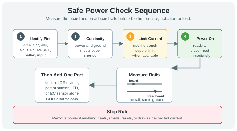
Run these checks before the first power-on:
- Identify the intended supply pin and ground pin.
- Confirm the supply voltage expected by the board or component.
- Look for accidental bridges between power and ground.
- Set a current limit if using a bench supply.
- Keep one hand ready to disconnect power if the circuit behaves unexpectedly.
Before you connect any sensor or actuator, measure the board supply rail while the board is running. Write down the value. That number becomes the reference for later checks.
4.8 Bring Up the Development Board
The first firmware test should be boring. Its job is to prove the development chain, not the final application.
4.8.1 Board Bring-Up Steps
- Connect the board by USB or its documented power input.
- Open the development tool and select the board family and communication port.
- Load a known-good test program that toggles an onboard indicator or prints a serial message.
- Upload the program and record whether the upload completes without error.
- Confirm the visible or serial output matches the expected timing.
- Save the board name, firmware file, tool version, and port in the prototype record.
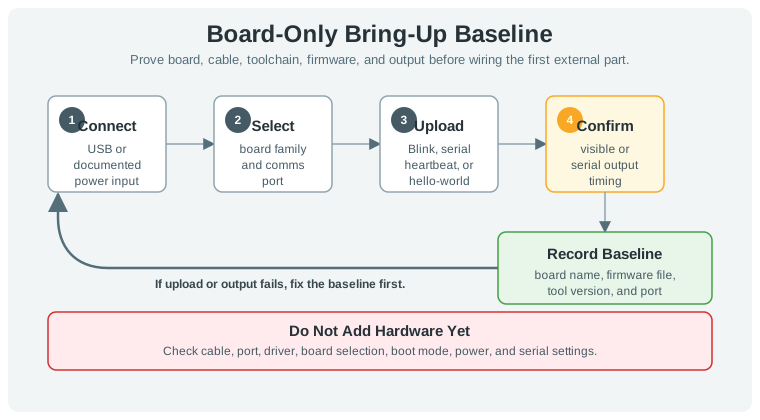
If this step fails, do not add hardware yet. Check cable, port, driver, board selection, boot mode, power, and serial settings before wiring external parts.
4.8.2 Read Board Labels Before Wiring
Development-board acronyms should be translated into a wiring record before the first jumper goes in. On a DragonBoard 410c-style single-board computer, the expansion headers expose pins and buses such as GPIO, MPP, I2C, SPI, UART, and PCM; the ports expose service paths such as HDMI, USB or MicroUSB, MicroSD, and DC input; and the board components include storage, RAM, Wi-Fi, GPS, and an ARM/RISC processor family. Those names are useful only after the record says which physical header, voltage domain, connector, storage path, or radio path the prototype actually uses.
Treat a 40-pin expansion header as a connector contract, not just a photograph. Number pins from the documented orientation, mark the repeated ground pins, keep power pins such as 1.8 V, 5 V, and SYS_DCIN separate from logic pins, and group multiplexed functions such as GPIO or MPP, I2C, SPI, UART, and PCM. Label each logic region with its voltage domain before wiring; for example, a DragonBoard-style pinout may put ordinary GPIO in a 1.8 V domain while an MPP or analog-capable region needs its own documented voltage note. The access method belongs in the record too: single jumper leads, a ribbon cable, a breadboard breakout, or a ribbon-cable breakout can all preserve or scramble the map depending on pin spacing, strain relief, and labeling.
Treat MPP as a multi-function pin family, not as a spare GPIO label. A DragonBoard-style MPP region may expose alternate roles, including analog I/O or board-specific peripheral functions, but it usually costs more reserved header space and more setup proof than a simple digital GPIO. Record the selected MPP function, voltage domain, pin number, and reason an ordinary GPIO, I2C, SPI, UART, or PCM path did not fit before wiring it into a prototype.
For Linux or Android-style single-board computers, GPIO access is also an operating-system boundary. A terminal or ADB recipe that exports pins under /sys/class/gpio, changes direction or value permissions, edits a boot script, or reboots the board is not just a command list; it is part of the prototype evidence. Record the OS image, SDK or shell route, privilege step, exported pin numbers, startup file changed, and final read/write check before treating the header pin as usable from Ubuntu commands or an Android app.
Programmatic GPIO access adds a second evidence layer. On an Android image, the boot-script change may run through adb root, remounting /system, an mksh shell, and an init.qcom.post_boot.sh edit that exports the needed pins and grants read, write, and execute access. After that, the application still has to prove how it reaches the pin: a GPIO library can make the code walkthrough clearer even if it is not efficient, a Gradle project gives the easier repeatable build path, and a manual import should be recorded as a time-consuming fallback. On Ubuntu or another Linux image, Python or another language can use the same verified GPIO library or file path, but the record should still name the build command, library version, pin map, and observed read/write result. For a beginner Python build, record whether the walkthrough used IDLE3, a shell, or another editor, show the import line that loads the GPIO library, keep the first program small enough to audit, and clean up or release the pin before claiming the example is repeatable.
Use the same habit for general bench vocabulary. An LED is an indicator load that still needs current limiting, a PCB is the fixed conductive path that a breadboard temporarily imitates, and an IC is the packaged circuit doing the real electrical work. IR and PIR should be recorded as sensing mechanisms, not vague “motion” claims. SDK, UI, and GUI should be recorded as software or user-facing boundaries. H-bridges, amplifiers, motors, and Bluetooth links should be treated as subsystems with their own driver, power, and evidence needs. If a legacy diagram uses master/slave wording, translate it in the record to controller/peripheral, central/peripheral, or controller/responder so ownership is clear without carrying the old label forward.
4.9 Build the First Breadboard Circuit
After the board-only test works, add one simple output or input. A small indicator output is a good first check because it makes timing and pin control visible.
4.9.1 Breadboard Rules
A solderless breadboard is a cheap, modular circuit board for mockups and tests. It gives easy access to connection nodes, but it is not clean or efficient enough to prove large-project layout, connector reliability, or field durability. Treat its internal metal pattern as part of the wiring map: terminal rows usually connect short horizontal groups on each side of the center divider, not across the divider, while side bus strips usually carry vertical power or ground rails and may be split on some boards. Confirm row continuity, rail continuity, and divider breaks with the same seriousness as pin labels.
For a small amplifier build, choose the prototype form deliberately. A breadboard amplifier usually needs fewer tools, less time, and less experience, and it is easy to change resistor values, swap the op-amp channel, or move the signal path while the requirement is still moving. A PCB or perfboard amplifier is smaller, tidier, and more repeatable, but it costs more setup time and freezes mistakes in pinout, rail choice, feedback wiring, and part placement. Use the breadboard to get the parts ready, prove the circuit, place one part family at a time, and record the working state before moving the same amplifier to copper.
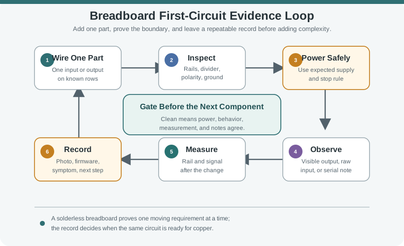
4.9.2 First Input and Output Pattern
A useful first prototype often has one input, one output, and one observable firmware response:
- Input: button, switch, light sensor, temperature sensor, or presence signal.
- Output: indicator, display message, buzzer, relay command, or motor command through a driver.
- Firmware response: read input, check threshold or state, update output, and print a short debug message.
- Evidence: supply voltage, raw reading or input state, output state, and a note about whether the behavior matched the expectation.
Use controller pins for signals. Loads such as motors, relays, heaters, long lighting runs, and pumps need an appropriate driver and power path.
4.10 Debug the First Failure
Most first-build failures are not mysterious. They usually come from power, ground, wrong pin, reversed part, missing resistor, mismatched signal level, wrong firmware target, or expecting too many new things to work at once.
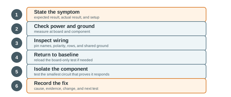
Use this ladder:
- State the symptom: What exactly failed, and what did you expect?
- Remove power: Do not move wires while the circuit is powered.
- Check power and ground: Measure supply voltage at the board and at the component.
- Inspect wiring: Confirm pin names, polarity, row placement, and shared ground.
- Return to baseline: Reload the known-good board-only test if the board behavior is uncertain.
- Test the component alone: Use the smallest circuit that proves the part responds.
- Record the fix: Note the cause, evidence, and change that resolved it.
4.10.1 Common First-Build Symptoms
4.11 Worked Scenario: First Room Monitor
The first project is a small room monitor with one environmental sensor and one indicator output. The goal is not a finished product. The goal is to prove the board, power, input reading, output control, and record habit.
4.11.1 Scenario Build Plan
4.11.2 First-Build Record
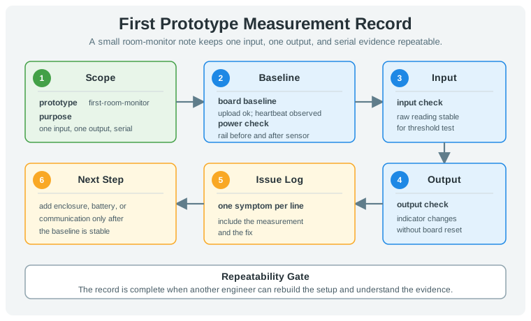
Use this compact record:
prototype=first-room-monitor
purpose=prove one input, one output, and serial output
board_baseline=upload ok, heartbeat observed
power_check=rail measured before and after sensor wiring
input_check=raw reading stable enough for threshold test
output_check=indicator changes without board reset
issue_log=one symptom per line with measurement and fix
next_step=add enclosure, battery, or communication only after baseline is stable
4.12 Knowledge Check
4.13 Match the First-Bench Evidence
4.14 Order the First Hardware Build
4.15 Common Failure Patterns
Large first builds create ambiguous failures. Start with one board, one input or output, and one measurement record.
Changing breadboard wiring while powered can create shorts, reversed connections, and misleading symptoms. Remove power before rewiring.
Wire color helps readability but does not prove correctness. Confirm the actual pin names, breadboard rows, and shared ground path.
If the first successful setup is not recorded, the next failure may require rediscovering the same wiring and firmware state from scratch.
4.16 Summary
Getting started with hardware prototyping means learning a repeatable bench workflow. Prove the board alone, power safely, add one component at a time, measure what changed, debug from the simplest symptom, and keep a short evidence record. That discipline lets later hardware chapters move faster without losing quality.
4.17 Key Takeaway
Start hardware prototyping with a narrow question, a known-good board, visible wiring, clear measurements, and a record another engineer can reproduce.
4.18 What’s Next
- Hardware Introduction - step back and review the broader hardware prototyping path.
- MCU vs MPU - choose the right controller class for the prototype.
- PCB Design - move from breadboard evidence toward layout decisions.
- Hardware Best Practices and Debugging - deepen the debugging workflow introduced here.