6 Choosing a Hardware Platform
Choose development boards, modules, gateways, and custom boards from prototype measurements
hardware platform selection, IoT development board choice, module carrier, gateway prototype, custom board transition, prototype platform validation

Phoebe’s Why
A development board’s onboard chip antenna and a gateway’s external panel antenna both start from the same fiction: an isotropic radiator that spreads power evenly over the whole sphere. A real antenna reshapes that sphere into a narrower lobe, trading the coverage angle it gives up for the power density it gains in the direction it keeps – that is what a gain number in dBi is quoting, and it is why “antenna clearance” and “antenna placement” belong on the platform’s evidence checklist next to boot time and sleep current. The bring-up bench also has a second, unrelated noise floor to measure: every ADC has its own quantization noise, fixed by its bit resolution, independent of whatever the antenna is doing.
The Derivation
Isotropic spreading, and gain redistributing the same power into solid angle \(\Omega\):
\[S_{iso} = \frac{P_t}{4\pi d^2} \qquad G = \frac{4\pi}{\Omega}\]
Effective isotropic radiated power:
\[\mathrm{EIRP}_{dBm} = P_{t,dBm} + G_{dBi}\]
Range scales with the square root of gain at fixed sensitivity and \(P_t\):
\[d \propto \sqrt{G}\]
ADC quantization noise for an \(N\)-bit converter, full-scale \(V_{FSR}\):
\[q = \frac{V_{FSR}}{2^N} \qquad e_{RMS} = \frac{q}{\sqrt{12}}\]
Worked Numbers: Onboard Chip Antenna vs. External Panel
- Catalog-typical onboard chip antenna (common on 2.4 GHz starter boards): \(P_t=0\) dBm, \(G=2\) dBi \(=10^{0.2}=1.58\times\). EIRP \(=2.00\) dBm \(=1.58\) mW.
- Catalog-typical external panel/Yagi for a gateway build, same \(P_t=0\) dBm: \(G=9\) dBi \(=10^{0.9}=7.94\times\). EIRP \(=9.00\) dBm \(=7.94\) mW.
- Range and coverage trade: range grows by \(\sqrt{7.94/1.58}=2.24\times\), while covered solid angle shrinks from \(1/1.58=63.1\%\) of the sphere to \(1/7.94=12.6\%\) – exactly why a panel-antenna gateway needs a placement and aiming record that a chip-antenna starter board does not.
- Separate noise budget – ADC: catalog-typical 12-bit ADC at \(V_{FSR}=3.3\) V, \(q=3.3/4096=0.806\) mV, \(e_{RMS}=0.806/\sqrt{12}=0.233\) mV. This quantization floor is fixed by the converter and is unrelated to the antenna gain above – both belong on the same bring-up checklist, but they are two independent margins, not one.
6.1 Start With the Story
Suppose a weather-station team can buy a starter board, a radio module carrier, a reference design, or a rugged gateway. Each option is tempting for a different reason, but the useful question is which one exposes the risk now: sensor noise, antenna placement, firmware upload, battery current, field mounting, or recovery after power loss.
This chapter treats platforms as evidence tools rather than shopping choices. A good platform decision names what the board will prove, what it cannot prove, and which measurement would disqualify it before the project depends on it.
6.2 Platform Is a Role
A hardware platform should be chosen because it answers the next prototype question with the least added uncertainty. The same board can be a learning tool, a throwaway demo platform, a production-intent module host, or the wrong abstraction depending on the stage.
For IoT work, the platform decision usually turns on five questions: local control, communication, power state, physical fit, and service path. A board that is excellent for firmware iteration may still hide enclosure, sleep-current, connector, antenna, or update risks.
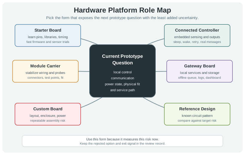
- Starter role: prove pins, libraries, timing, sensor behavior, and debugging flow quickly.
- Connected-node role: prove embedded sensing, local outputs, sleep/wake behavior, and real message paths.
- Gateway role: prove local storage, protocol translation, offline behavior, dashboards, service logs, and field diagnostics.
For example, an ESP32 DevKitC, Raspberry Pi Pico W, Arduino Nano 33 IoT, STM32 Nucleo board, Nordic nRF52 DK, Adafruit Feather, or Seeed XIAO can all be useful IoT platforms, but they do not answer the same question. A Pico W may be a fast way to learn MicroPython GPIO and Wi-Fi behavior. An nRF52840 board may be better when Bluetooth Low Energy or Thread behavior matters. A Raspberry Pi or Compute Module may be a gateway platform when the evidence is local Linux services, files, camera input, or a dashboard. A custom carrier becomes useful when connector strain, test points, enclosure clearance, and assembly repeatability are the next unknowns.
For a first “build your own IoT” path, the practical options are usually a microcontroller, a single-board computer, or a phone-backed prototype. A microcontroller is the right shape when the learner must prove GPIO, sensor sampling, actuator timing, sleep current, and radio behavior. A single-board computer, including older DragonBoard 410c-style Linux boards, is the right shape when the evidence is local files, camera input, higher-level services, or gateway behavior. A smartphone can be a useful prototype surface when the question is location, camera, accelerometer, permission flow, or user interaction, but it should be recorded as a phone-mediated system rather than as proof that the final embedded node can meet power or recovery targets.
The platform choice should therefore be written as an evidence sentence: “Use this form because it can measure this risk now.” If the sentence only says “we know this board” or “it has enough compute”, the team has not chosen a platform role. The review should name the present evidence gap, the board or form that exposes it, the risk the form hides, and the exit signal for moving to a module carrier, gateway, or custom board.
6.3 Practitioner: Shortlist by Risk Removed
A useful shortlist names what each platform form can prove. Arduino Uno, Arduino Nano 33 IoT, Raspberry Pi Pico W, ESP32 DevKit, STM32 Nucleo, Nordic nRF52 DK, and Adafruit Feather boards make different tradeoffs in pin access, radios, power, toolchains, shields, and ecosystem support. Raspberry Pi, Compute Module, BeagleBone, Jetson Nano, and small x86 gateways make different tradeoffs in Linux services, storage, camera/display support, and power draw.
- Measure endpoint fit: boot time, sleep current, wake time, radio attach time, ADC noise, GPIO drive path, firmware update route, and watchdog recovery.
- Measure gateway fit: cold boot, service restart, storage resilience, offline queue length, local UI response, network reconnect, logs, and remote access.
- Measure physical fit: connector strain, mounting holes, antenna clearance, sensor exposure, enclosure clearance, cable exit, test-point access, and assembly repeatability.
- Measure transition cost: pinout migration, module availability, carrier-board complexity, library lock-in, supply risk, certifications, and custom-board effort.
Start with two or three plausible forms, not ten boards. For a battery sensor node, compare a development board with the target radio module, a module carrier, and a reference-design board. For a gateway, compare a Raspberry Pi-class single-board computer, an industrial gateway, and the lowest-power Linux-capable option that can still run the needed services. For each option, record the measurement that would disqualify it: active current, deep-sleep current, wake time, radio attach time, sensor noise, storage corruption after power loss, enclosure interference, or inability to recover firmware.
Use real evidence tools during the shortlist. A Nordic Power Profiler Kit II, Joulescope, bench supply with current limit, USB power meter, logic analyzer, oscilloscope, serial console, Wireshark trace, MQTT broker log, or systemd journal can make the platform comparison concrete. Firmware-tool evidence matters too: Arduino IDE, PlatformIO, ESP-IDF, Zephyr with west, STM32CubeIDE, pyOCD, OpenOCD, esptool.py, nrfjprog, and Raspberry Pi OS all change how fast the team can flash, log, recover, and repeat tests. The winning platform is the one that removes the current uncertainty without making the next transition unreasonably expensive.
Keep a rejected option in the record. If an ESP32 board was rejected because its USB-UART circuit and regulator hid sleep current, say so. If a Raspberry Pi was rejected because boot time, storage writes, or power draw were irrelevant to the sensor-node question, write that down. If a module carrier was deferred because the team had not stabilized pinout or sensor placement, record the exit criteria that would trigger it.
6.4 Convenience Hides Product Risk
Development convenience is real value, but it should be separated from deployment risk. USB power, breadboard headers, onboard LEDs, auto-reset circuits, SD cards, desktop Linux images, and shield ecosystems speed learning while hiding the behavior of the final device.
- Power risk: USB-powered demos can hide battery chemistry, regulator heat, inrush current, low-voltage lockout, and sleep leakage.
- Communication risk: lab Wi-Fi can hide LoRaWAN, LTE-M, NB-IoT, BLE, Ethernet, RS-485, Thread, or Matter commissioning behavior.
- Mechanical risk: jumper wires and shields can hide connector keying, cable strain, antenna placement, exposed sensors, gasket pressure, and service access.
- Operations risk: dev images can hide secure boot, signed OTA updates, credential storage, remote logs, recovery mode, and fleet provisioning.
Many board-level differences are hidden in support circuits rather than the main processor. A development board may include a USB-to-UART bridge, linear regulator, charger, power LED, level shifter, auto-reset circuit, pull resistors, boot-mode strapping, or solder-jumper defaults that are not present in the final design. Those parts can change idle current, reset timing, ADC noise, radio behavior, and first-power symptoms. The platform review should name which support circuits are part of the evidence and which are merely conveniences.
Software layers create similar risk. An Arduino core may hide ESP-IDF configuration, a vendor BSP may hide clock and pin defaults, and a Raspberry Pi image may hide Linux service dependencies, filesystem writes, udev rules, NetworkManager behavior, and shutdown recovery. A board that works in the lab can still fail the evidence question if it cannot expose boot logs, watchdog resets, radio reconnects, flash wear, certificate storage, or signed-update failure paths. When the platform includes a radio module, check the module datasheet and reference layout assumptions: antenna keep-out, ground plane, matching network, regulatory modular approval, and enclosure effects are not proven by a USB-powered bench demo.
The platform has done its job when it exposes the next risk clearly enough to choose the next form. That may mean moving from an Arduino-class starter board to an ESP32 or nRF52 connected node, from loose modules to a carrier board, from a laptop-hosted script to an embedded gateway, or from a module carrier to a custom PCB. The under-the-hood test is whether the next transition is based on measured behavior rather than the comfort of the board already on the bench.
6.5 Learning Objectives
By the end of this chapter, you will be able to:
- Explain the difference between a platform role and a specific board.
- Match platform forms to prototype evidence needs.
- Compare starter boards, connected controller boards, module carriers, gateway boards, and custom boards by the questions they answer.
- Decide when to move from a flexible platform to a more constrained hardware form.
- Write a platform selection record that preserves the rationale for later revision.
6.6 Platform Choice Is a Prototype Decision
Platform selection should begin with the next evidence gap, not with a familiar board name. A platform is useful when it reduces uncertainty without adding a larger problem.
Ask what the current prototype must prove:
A popular board can make early progress fast, but it can also hide power, connector, enclosure, service, or field-recovery risks. Keep the platform accountable to the prototype question.
6.7 Platform Forms and What They Prove
Each platform form answers a different class of question. Treat the form as a stage-gate choice.
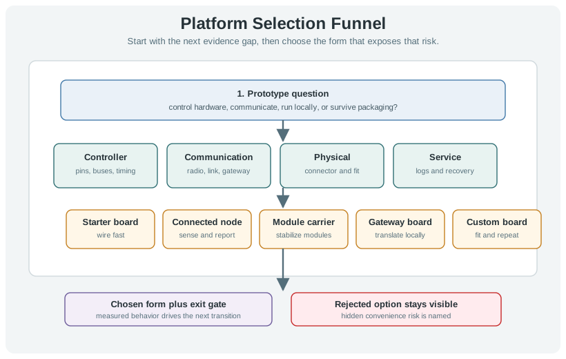
6.7.1 Avoid False Comparisons
Comparing platforms by a single feature is usually misleading. A board with more processing headroom may be weaker for battery sleep. A board with fast software iteration may be weaker for deterministic I/O. A board with convenient connectors may be too large for the intended enclosure.
6.8 Platform Fit Matrix
A platform shortlist should be reviewed against constraints that can be measured or inspected. Use the matrix to record what each candidate can prove and where it may hide risk.
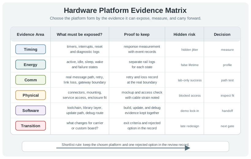
Review these evidence areas:
Keep at least one rejected option in the review record. A good platform decision explains why the chosen form fits now and why a plausible alternative was not selected.
6.9 Transition Timing
Early platforms are flexible because they are easy to change. Later platforms are useful because they remove ambiguity. Move forward when the current platform is no longer answering the real question.
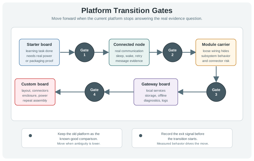
Use these transition signals:
Do not discard an early platform immediately. Keep it as a known-good comparison while the next platform is being brought up.
6.10 Worked Scenario: Cold Storage Monitor
A team is building a cold storage monitor for small facilities. The device must read several sensors, report events to a nearby gateway, keep working during short network outages, and fit inside a small enclosure with external probes.
6.10.1 Platform Path
6.10.2 Platform Review Record
prototype=cold-storage-monitor
stage=functional-prototype
current_question=can sensor nodes report events through a local gateway during intermittent network loss?
chosen_platform_form=connected-controller-node plus gateway-board
why_node=local sensing, low-energy state measurement, event retry, and warning output
why_gateway=local buffering, reconnect behavior, status display, and service logs
rejected_option=single gateway-only design because it cannot prove distributed probe placement
next_transition=module carrier for connectors, test points, and enclosure fit
6.11 Platform Handoff Record
When a platform is selected, leave a record that future reviewers can challenge. Platform decisions often become hard to revisit after firmware, wiring, and test fixtures accumulate around them.
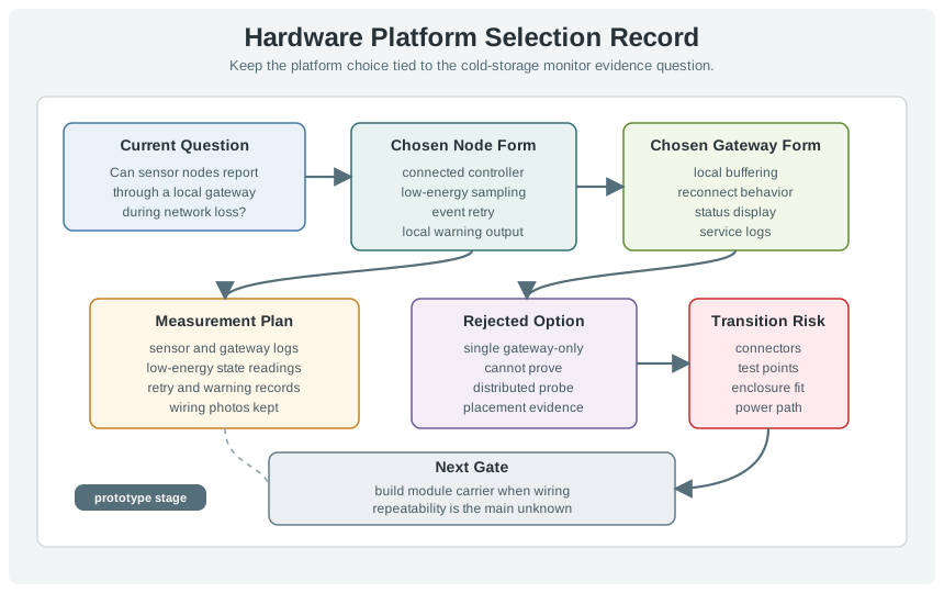
Record:
6.12 Knowledge Check
6.13 Match Platform Form to Evidence
6.14 Order the Platform Selection Review
6.15 Common Failure Patterns
The review names a board but does not explain whether it is acting as a starter board, connected controller, gateway, carrier, or transition path. The team cannot tell when the platform has stopped being useful.
A simulator can help with syntax, logic, or rough timing, but it does not prove connector orientation, power behavior, sensor noise, antenna placement, enclosure fit, or field recovery.
A platform with an easy setup can hide low-energy behavior, boot recovery, service access, or layout constraints. Review convenience separately from the evidence needed next.
The prototype stays on the same platform because the team never defined what evidence would trigger a carrier, gateway, or custom-board transition.
6.16 Summary
Hardware platforms are temporary evidence tools. Choose the platform form that answers the current prototype question, record the rejected alternatives, and define the transition risk before the team builds too much around a convenient board.
6.17 Key Takeaway
Prototype platforms are decision tools: select the board that exposes the right interfaces, ecosystem, power behavior, and migration path for the evidence you need.
6.18 What’s Next
- AI, Wireless and Energy Kits - evaluate specialized kit categories without treating kits as architecture.
- Industrial and Wearable Kits - review kit fit for constrained field environments.
- Kit Selection Best Practices - apply platform evidence to kit selection.
- MCU vs MPU - revisit controller-class decisions that sit underneath platform form choices.