22 AI, Wireless, and Energy Kits
Use specialized kits to answer measurement questions without locking the product design too early
AI prototyping kit, wireless evaluation kit, energy harvesting prototype, IoT kit measurement, prototype kit selection
22.1 Start With the Story
AI, wireless, and energy kits can make advanced capabilities look simple. A model can classify a sound, a radio can send a packet, and an energy board can harvest a little power, but the prototype question is whether those claims survive the project’s limits. The team needs evidence for latency, accuracy, range, airtime, current draw, storage, and fallback behavior.
Use this chapter to keep advanced kits grounded. Start with the evidence question, run a representative slice, and mark exactly which performance, wireless, or power assumptions must be retested before the design scales.
22.2 Specialized Kits Shrink Unknowns
AI, wireless, and energy kits are useful when they isolate a difficult subsystem before the full product form exists. The danger is treating the kit’s demo path as the architecture, enclosure, radio plan, power budget, or service model.
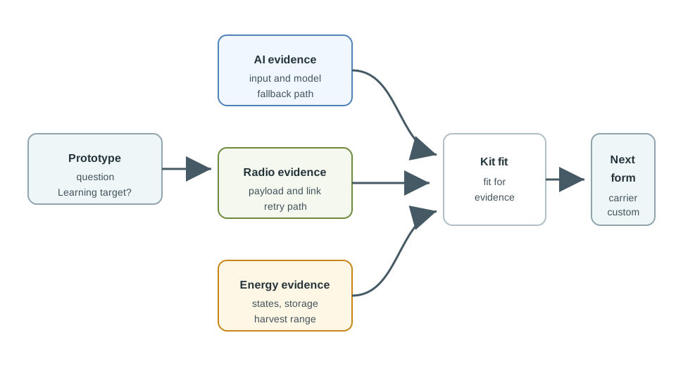
Use each kit to answer one measured question: inference feasibility, link behavior, or energy rhythm. Then decide what survives into a carrier board, custom board, gateway, enclosure, or field pilot.
- AI kit question: can the target input be captured, preprocessed, inferred, thresholded, and recovered within timing, memory, heat, and update limits?
- Wireless kit question: can the intended payload survive placement, interference, antenna orientation, retries, gateway restart, and provisioning?
- Energy kit question: can boot, sensing, inference, transmit, receive, sleep, and recovery fit within the harvested or stored energy pattern?
For example, a camera trap team might use an Arduino Nicla Vision, Seeed XIAO ESP32S3 Sense, or Raspberry Pi with a Coral USB accelerator to learn whether a compact model can distinguish animal motion from shadows. That test should log frame size, preprocessing time, inference time, confidence threshold, missed events, false events, temperature, and recovery after a bad input. It should not decide the enclosure, radio, or battery architecture by itself. The kit answers the model question and leaves the product question open.
The same team might use a RAKwireless LoRaWAN gateway, Semtech LoRa-E5 module, Nordic nRF52840 DK, or LTE-M/NB-IoT module such as Quectel BG95 to test the alert path separately. A Joulescope, Otii Arc, Nordic Power Profiler Kit II, TI BQ25570 board, e-peas AEM10941 board, solar panel, supercapacitor, or LiFePO4 cell can then test the state timeline. The useful output is not a polished all-in-one demo; it is a map of which evidence came from which kit and which evidence must repeat when the boards, antennas, lenses, power store, or enclosure change.
22.3 Name Kit Class and Measurement
AI experiments may use TensorFlow Lite Micro, Edge Impulse, NVIDIA Jetson Nano or Orin Nano, Google Coral USB or M.2 accelerators, Arduino Nicla Vision, or Seeed XIAO ESP32S3 Sense. Wireless experiments may use Nordic nRF52840 DK, Silicon Labs EFR32 kits, Semtech LoRa or LoRa-E5 modules, RAKwireless gateways, Quectel BG95 LTE-M/NB-IoT modules, ESP32 Wi-Fi/BLE boards, or Matter/Thread development kits. Energy experiments may use Joulescope, Otii Arc, Nordic Power Profiler Kit II, e-peas AEM10941 boards, TI BQ25570 boards, solar panels, supercapacitors, and LiFePO4 cells.
- For AI: log capture time, preprocessing time, inference time, memory use, confidence threshold, false positives, false negatives, thermal rise, and fallback output.
- For wireless: log RSSI/SNR, packet delivery, retry count, acknowledgement delay, join/provisioning time, gateway recovery, antenna orientation, and coexistence notes.
- For energy: log current versus time for boot, sensor warmup, inference, transmit burst, receive window, sleep, wake source, storage charge, and brownout recovery.
- For handoff: mark which board, antenna, lens, model, firmware, power source, library, or enclosure assumption is kit-only.
A practitioner should make the measurement plan fit the kit role. For AI, keep a small reviewed input set with labels, expected output, model version, quantization setting, threshold, and timing breakdown. Edge Impulse, TensorFlow Lite Micro, ONNX Runtime, OpenVINO, or TensorRT results are only useful if the record says which preprocessing path and input quality were tested. A model that looks good on five clean images may fail on motion blur, glare, dust, vibration, or a low-light frame from the real mounting position.
For wireless, record the environment rather than only the board. A LoRaWAN test should include spreading factor, transmit power, gateway id, RSSI, SNR, confirmed or unconfirmed uplink choice, join time, retry behavior, and antenna position. A BLE or Thread/Matter test should include provisioning path, phone or border-router role, reconnection behavior, and interference notes. For energy, capture a timeline with state names and trigger events: boot, sensor warmup, capture, inference, transmit, receive window, storage write, sleep, wake, and brownout recovery. Without that timeline, average current can hide the burst that actually breaks the device.
22.4 Integration Fails Between Kits
Separate kit experiments can all pass and still fail together. Local inference may heat the enclosure before a radio burst. A camera angle may require an antenna location that detunes the link. A harvest schedule may support sensing but not model update or reconnect behavior.
- Timing coupling: align image capture, DSP, inference, transmit, receive window, flash write, and sleep entry so burst overlap is visible.
- Power coupling: compare peak current, average current, storage voltage, regulator dropout, cold-start threshold, and brownout flags across the combined sequence.
- Physical coupling: check lens view, microphone opening, antenna keep-out, heat path, cable strain, panel illumination, and service access in the intended enclosure.
- Operations coupling: verify provisioning, model update, key rotation, firmware rollback, local logs, replacement flow, and support diagnostics after kit boards are removed.
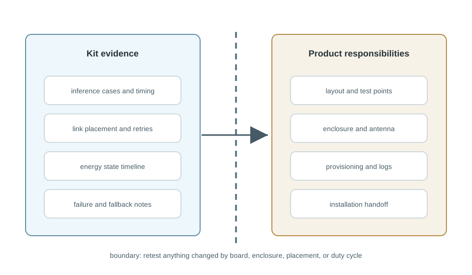
The integration boundary should say what each kit proved, what it did not prove, and which check must repeat when the product form changes.
Under the hood, the hard part is often shared resources. A camera sensor, neural accelerator, radio module, flash chip, charger, fuel gauge, and microcontroller may compete for I2C or SPI buses, DMA buffers, interrupt lines, regulator headroom, thermal budget, and wake timing. A Jetson or Coral prototype may prove inference, but the final microcontroller cannot inherit its memory bandwidth or Linux driver stack. A LoRa kit may prove range, but the final enclosure and antenna feed can change link margin. An energy board may prove harvesting, but not when inference and transmit bursts overlap.
Good integration records therefore include interfaces and invariants, not just screenshots. Name voltage rails, peak current, regulator dropout limit, bus speed, antenna keep-out, model file, firmware hash, key store, provisioning method, OTA path, low-energy policy, and diagnostic log source. When the carrier board, custom PCB, enclosure, or gateway changes, the record tells the team which measurements must be repeated. That is how specialized kits reduce risk without smuggling kit-only assumptions into the product design.

Phoebe’s Why
This chapter’s wireless kits (a RAKwireless gateway, a Semtech LoRa-E5 module) and its energy kits (a TI BQ25570 harvester, a solar panel, a supercapacitor) usually get evaluated on separate benches, but a radio’s antenna and a node’s energy budget are the same physics problem seen from two directions. An antenna does not create power – it reshapes it, concentrating a fixed transmit power into a narrower cone. That means every dBi of antenna gain is a dB of transmit power the radio module does not have to spend to reach the same effective range, and for a harvested-energy node, the transmitter’s power is the one thing that has to be paid for out of the energy kit’s own harvested budget, milliamp by milliamp. A passive antenna choice is a free lever; a transmit-power increase is not.
The Derivation
Effective radiated power ties the radio’s setting to the antenna’s gain, so either term can supply the same target:
\[\mathrm{EIRP(dBm)} = P_{tx}\mathrm{(dBm)} + G\mathrm{(dBi)}\]
Converting a dBm transmit setting to the linear power an energy budget actually spends:
\[P_{tx}\mathrm{(mW)} = 10^{P_{tx}\mathrm{(dBm)}/10}\]
Energy spent per uplink is that power held for the transmit burst, which a harvester must then replace:
\[E_{tx} = P_{tx}\,T_{tx}, \qquad t_{recharge} = \frac{E_{tx}}{P_{harvest}}\]
Worked Numbers: Two Ways To Hit The Same Target EIRP
- Stub antenna, all power: \(P_{tx}=14.0\) dBm into \(G=0\) dBi gives \(\mathrm{EIRP}=14.0\) dBm; \(14.0\) dBm \(=10^{1.4}=25.1\) mW conducted.
- Small gain antenna, less power, same coverage: \(P_{tx}=11.0\) dBm into a catalog-typical \(G=3.00\) dBi small directional element gives the identical \(\mathrm{EIRP}=14.0\) dBm, but only \(10^{1.1}=12.6\) mW conducted – \(49.9\%\) less transmit power for the same closed link.
- Per-uplink energy, an illustrative 60.0 ms airtime: the all-power option costs \(25.1\times0.0600=1.51\) mJ per uplink; the antenna-gain option costs \(12.6\times0.0600=0.755\) mJ – exactly half.
- Against a catalog-typical 100 µW indoor-harvest budget (a small photovoltaic cell feeding a BQ25570-class harvester under office lighting): the all-power uplink needs \(1.51\ \text{mJ}/0.100\ \text{mW}=15.1\) s of harvested energy to recharge; the antenna-gain uplink needs only \(0.755/0.100=7.55\) s – the \(0\)-cost antenna choice buys back half the harvester’s recovery time between transmissions, without touching firmware, radio silicon, or harvest area.
This is the energy-kit question this chapter already asks – “can transmit fit within the harvested pattern?” – with the wireless kit’s own antenna choice folded into the same ledger instead of a separate bench result.
22.5 Learning Objectives
By the end of this chapter, you will be able to:
- Match AI, wireless, and energy kits to the uncertainty they are best suited to reduce.
- Separate kit evidence from final product decisions.
- Build a review matrix for model behavior, link behavior, energy states, physical fit, and handoff risk.
- Plan staged experiments that combine specialized kits without creating a fragile one-off prototype.
- Write a kit review record that helps the next reviewer challenge or revise the decision.
22.6 Start With the Evidence Question
Specialized kits are most useful when the team needs to learn quickly without first designing every board, enclosure, service, and test fixture. The mistake is treating the kit as a ready-made product direction. A kit should answer a focused question, then hand that answer to the next prototype stage.
Use a specialized kit when the next unknown is hard to isolate with a general starter board:
The best kit for one subsystem can be the wrong choice for the whole prototype. It is often cleaner to run separate AI, wireless, and energy experiments, then integrate only the evidence that survives review.
22.7 What Each Kit Category Is Good For
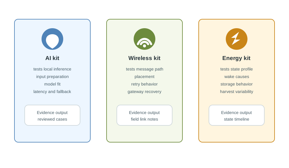
AI, wireless, and energy kits look similar because they arrive as boards, adapters, examples, and documents. Their useful evidence is different.
22.7.1 Use Multiple Kits Deliberately
A remote monitor might need local image classification, long-distance event reporting, and a strict energy budget. That does not mean one board should prove everything at once. The AI kit can answer whether local inference is feasible. The wireless kit can answer whether the message path survives placement and interference. The energy kit can answer whether the final duty cycle is plausible. Integration should happen after each subsystem has produced reviewable evidence.
22.8 AI Kits: Local Inference Measurements
An AI kit is useful when the prototype must make decisions near the sensor instead of sending every raw input elsewhere. The kit should be judged by the evidence it creates, not by its headline acceleration feature.
Evaluate an AI kit with these questions:
Record a few representative inputs, the expected output, the observed output, timing, confidence, and a note about why the result matters. A large demo video is less useful than a concise table of reviewed cases.
22.9 Wireless Link and Topology
A wireless kit is useful when the prototype must prove communication behavior in a real environment. Bench success is not enough. The review should include placement, antenna orientation, gateway location, message size, retries, and recovery after interruption.
Review a wireless kit by evidence area:
22.9.1 Range Claims Need Field Evidence
Published radio capability rarely describes the exact installation. A short, structured placement test is more valuable than a broad range claim because it ties the result to the environment the product must survive.
22.10 Duty Cycle and Harvesting
Energy kits are useful when the prototype must prove that the device can operate through real active, idle, sleep, wake, and recovery states. The goal is not just to show that a source can generate energy. The goal is to show that the system’s rhythm can live within the available energy envelope.
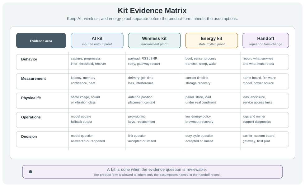
Measure or inspect:
Average consumption can hide failure. Record the sequence of events, how long each state lasts, and what causes the next state. This exposes bursts, wake storms, and recovery gaps.
22.11 Integration Boundary
The kit proves subsystem behavior. It does not automatically prove the final product. Before combining kit results, draw a boundary between kit evidence and product responsibilities.
22.12 Remote Equipment Monitor
A team is prototyping a remote equipment monitor. The device should detect a visual event, send a compact alert through a low-power link, and operate from a limited energy source. The team avoids choosing a single “best” kit. Instead, it stages the evidence.
22.12.1 Stage 1: AI Evidence
The AI kit is mounted where the future sensor might sit. The team records representative frames, inference timing, confidence thresholds, false positives, and fallback behavior when the image is partially blocked. The result is a review record for the model, preprocessing, and alert threshold.
22.12.2 Stage 2: Wireless Evidence
The wireless kit sends only the intended alert payload. The team tests the likely sensor and gateway positions, records retries, checks recovery after gateway restart, and notes enclosure and antenna constraints that must be checked later.
22.12.3 Stage 3: Energy Evidence
The energy kit measures boot, standby, capture, inference, transmit, receive, and sleep states separately. The team adjusts the duty cycle so visual checks, wireless alerts, and local logging do not happen in a way that drains the storage element before recovery.
22.12.4 Stage 4: Integration Review
The team combines the evidence in a review record instead of forcing all boards into one fragile prototype. The next prototype can use a carrier or custom board because the model, link, and energy assumptions are now explicit.
prototype=remote-equipment-monitor
current_question=can visual event detection, compact alerts, and energy recovery work together?
ai_evidence=representative inputs, inference timing, confidence threshold, fallback behavior
wireless_evidence=alert payload, placement notes, retry behavior, gateway recovery
energy_evidence=state timeline, wake causes, storage recovery, low-energy fallback
integration_boundary=kit boards prove subsystems; next board must check enclosure, antenna, heat, and power path again
rejected_option=single all-in-one demo board because it hides subsystem failures
next_step=carrier prototype with stable connectors, test points, antenna position, and energy probes
22.13 Kit Review Record
Leave a record that another reviewer can challenge. A good record explains why the kit was used, what evidence it produced, what was rejected, and what must be checked again after the kit is replaced.
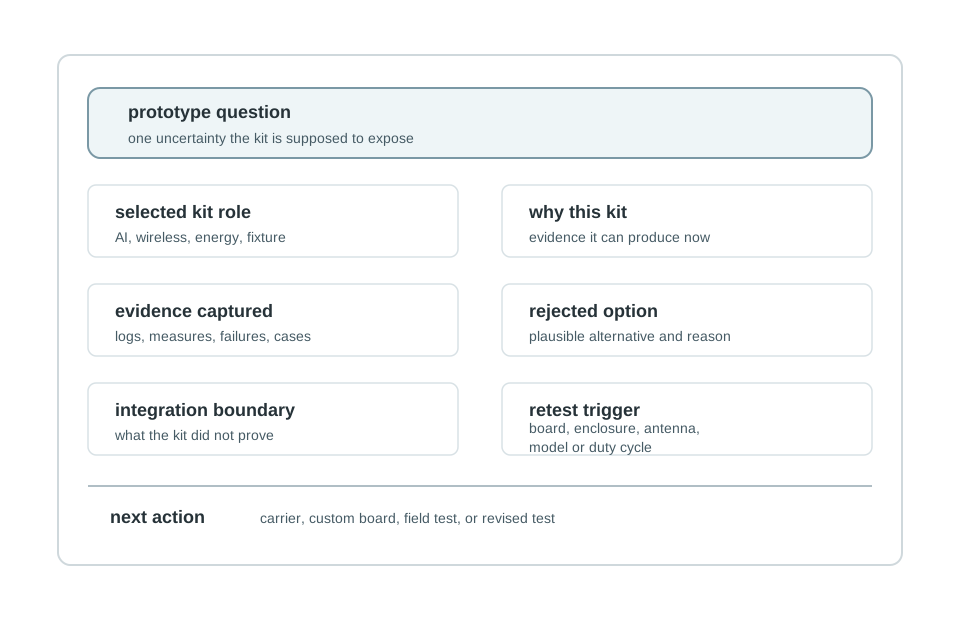
Use this template:
prototype=
stage=
current_question=
selected_kit_role=
why_this_kit=
evidence_captured=
rejected_option=
integration_boundary=
change_condition=
next_action=
review_owner=
review_date=
22.14 Knowledge Check
22.15 Common Failure Patterns
22.16 Summary
- AI kits are best used to test local inference behavior, not to choose the final compute architecture by default.
- Wireless kits are best used to test message, placement, retry, gateway, and recovery behavior in the real environment.
- Energy kits are best used to test state timelines, wake causes, storage behavior, harvesting variability, and fallback behavior.
- Integration should preserve evidence and expose boundaries instead of turning several kits into an unreviewable demo.
- A clear review record makes the decision revisable when the prototype moves to a carrier, custom board, enclosure, or field installation.
22.17 Key Takeaway
Specialized kits are useful when their accelerators, radios, or energy features match the use case and can still be validated outside the vendor demo path.
22.18 What’s Next
| If you want to… | Read this |
|---|---|
| Review kit selection across broader project constraints | Kit Selection Guide |
| Compare specialized domain kits for industrial and wearable prototypes | Industrial and Wearable Kits |
| Plan the move from kit evidence to board-level hardware decisions | Hardware Platform Selection for IoT Prototypes |