20 Robotics and Agricultural Kits
Use motion and field kits to collect evidence before committing to a robot, outdoor node, or site deployment
robotics prototyping kit, agricultural IoT kit, outdoor sensor prototype, motion-control evidence, field deployment evidence
20.1 Start With the Story
A robotics or agricultural kit often combines motion, sensing, weather, power, and communication in one exciting box. That makes the prototype fun, but it also makes the evidence easy to blur. The story should begin with one operational question: can the system move safely, sense reliably, recover outdoors, conserve energy, or leave a field record that another person can inspect?
Use this chapter to slow the kit down into reviewable lanes. Match the kit to the environment, measure the risky behavior, and keep the handoff record honest about what remains unproven.
20.2 Motion and Field Kit Risks
A robotics kit should make movement reviewable: drive geometry, traction, steering, braking, payload, obstacle sensing, localization, path following, emergency stop, and recovery. A smooth demo on a lab floor does not prove the route, surface, load, or safety state the product will meet later.
An agricultural kit should make field survival reviewable: soil contact, shade, water, dust, animals, calibration, coverage, solar exposure, battery behavior, service interval, and local reference readings. A clean bench reading does not prove a node can make useful decisions in a bed, field, greenhouse, barn, or orchard.
- Robotics question: can the prototype move and recover safely under the surfaces, loads, paths, and supervision the task requires?
- Agricultural question: can the prototype sense, communicate, stay powered, and remain serviceable in the actual placement context?
- Integration question: what state contract joins robot observations, field readings, gateway status, stale-data flags, and human override?
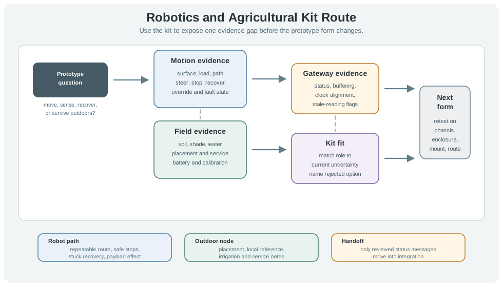
Treat the kit as an evidence instrument, not a shortcut to the final product. The same greenhouse example can need a TurtleBot-class mobile base for aisle movement, a separate LoRaWAN or Wi-Fi field node for bed readings, and a gateway fixture for buffering and clock alignment. Combining those boards too early creates a demonstration that looks integrated but hides which subsystem failed. A stronger first pass keeps the evidence lanes separate: motion logs prove route repeatability and safe stops, field logs prove placement and calibration, and coverage logs prove whether the site can report stale or missing data.
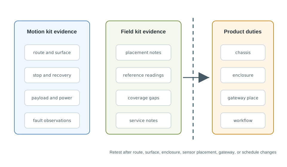
The handoff matters as much as the demo. A robotics kit result should say which surface, payload, battery, sensor height, and override condition was tested. An agricultural kit result should say which soil depth, shade condition, irrigation exposure, enclosure state, and service interval was tested. When the team changes the chassis, enclosure, antenna, gateway location, or operating schedule, those evidence fields become the retest list.
20.3 Name Stack, Sensor, Field Risk
Robotics experiments may use TurtleBot 3 or TurtleBot 4, Clearpath Jackal, ROS 2, micro-ROS, Gazebo or Isaac Sim for pre-field checks, NVIDIA Jetson Nano or Orin Nano, Raspberry Pi, STM32 or Arduino motor-control boards, Pololu drivers, ODrive controllers, Dynamixel servos, wheel encoders, RPLIDAR or Hokuyo lidar, Intel RealSense D435 cameras, emergency-stop circuits, and RTK GNSS receivers. Agricultural experiments may use RAKwireless WisBlock nodes, Arduino MKR WAN boards, Dragino LoRaWAN nodes, Seeed SenseCAP sensors, Milesight EM500 devices, METER TEROS soil sensors, SHT31 or BME280 environmental sensors, DS18B20 probes, tipping-bucket rain gauges, PAR sensors, solar charge boards, LiFePO4 packs, and LoRaWAN gateways.
- For motion: log wheel slip, encoder counts, motor current, battery sag, stop distance, obstacle range, route deviation, map update, localization loss, override input, and fault-state transition.
- For field sensing: log sensor depth, mounting height, shade, irrigation exposure, soil type, local reference sample, calibration method, weather note, enclosure condition, and last service action.
- For coverage: log LoRaWAN RSSI/SNR, packet delivery, join time, gateway placement, offline queue length, timestamp freshness, duplicate status, stale-reading display, and restart recovery.
- For handoff: mark which chassis, wheel, actuator, sensor mount, antenna, enclosure, solar panel, battery, gateway, firmware package, and maintenance assumption is kit-only.
A practical review usually needs a small evidence table before a large dashboard. For a robot, record commanded velocity, measured wheel speed, motor current, encoder count, IMU yaw drift, obstacle range, localization confidence, controller state, stop reason, and operator override. For a field node, record sensor model, calibration reference, depth or height, sample interval, radio path, gateway identifier, battery voltage, charge state, enclosure condition, and service note. Keep timestamps in one clock domain when possible, or record clock offset explicitly when the robot logger, field node, and gateway do not share time.
Use simulation carefully. Gazebo, Isaac Sim, or a ROS 2 Nav2 test can expose path-planning and fault-state assumptions before hardware is risked, but it cannot prove traction, ingress, solar recovery, crop occlusion, or maintenance access. A useful practitioner record says which results came from simulation, which came from bench motion, which came from field placement, and which must be repeated after the prototype form changes.
20.4 Outdoor Robots Fail at Edges
The hard failures are usually at the boundary between mechanical motion, sensing, power, connectivity, and human supervision. A greenhouse scout may pass navigation indoors and still fail on wet concrete, wheel slip, narrow aisles, occluded crop rows, reflective plastic, low sun, a stuck caster, a depleted battery, or a blocked emergency-stop path.
- Control boundary: separate command source, actuator state, limit switch, watchdog, emergency stop, manual override, safe stop, and restart path before adding autonomy.
- Perception boundary: check lidar blind spots, camera exposure, dust, crop movement, rain, fog, map drift, RTK correction loss, and sensor cleaning before trusting a route plan.
- Field-node boundary: check ingress, condensation, cable strain, rodent damage, probe corrosion, solar shading, charge-controller recovery, and low-temperature battery behavior before calling a node field-ready.
- Operations boundary: verify who can start, stop, recover, recalibrate, clean, charge, replace, and override the prototype, and what the dashboard says when readings or robot status are stale.
Many failures are state-contract failures rather than single component failures. A robot may publish a healthy navigation state while the field gateway is buffering stale bed readings; a field node may publish a valid soil value while its calibration reference is outdated; a dashboard may show the latest robot position without showing that manual override is active. Define states such as moving, blocked, safe_stop, offline_buffering, reading_stale, needs_service, and override_active before the subsystems are joined.
Power and timing also cross the boundary. Motors create current spikes and electromagnetic noise that can disturb sensing or radio modules; solar field nodes create long dark-period behavior that a bench supply never shows; gateway restarts can reorder messages unless timestamps, sequence numbers, and freshness rules are explicit. The under-the-hood review should therefore capture both raw measurements and the rule that turns them into a safe system state.
The kit result is useful only when the next prototype knows which motion, field, coverage, power, and workflow tests must repeat after the physical form changes.
20.5 Learning Objectives
By the end of this chapter, you will be able to:
- Match robotics and agricultural kit roles to the evidence they can produce.
- Separate motion-control evidence from outdoor field evidence.
- Build a review matrix for actuation, sensing, coverage, energy, environment, workflow, and handoff risk.
- Plan a staged prototype that combines mobile and field evidence without hiding failures.
- Write a review record that captures assumptions, rejected options, and change conditions.
20.6 Motion and Field Evidence
Robotics kits and agricultural kits often appear together in automation projects, but they should not be reviewed as if they solve the same problem. A robotics kit is useful when the prototype must move, steer, stop, sense nearby hazards, or navigate a repeatable path. An agricultural kit is useful when the prototype must live outside, measure changing environmental conditions, communicate across a site, and survive long service intervals.
Start by naming the evidence gap:
A moving robot beside outdoor sensors can look impressive while proving little. Keep the first tests narrow enough that motion failures, sensing failures, and coverage failures remain visible.
20.7 Kit Roles
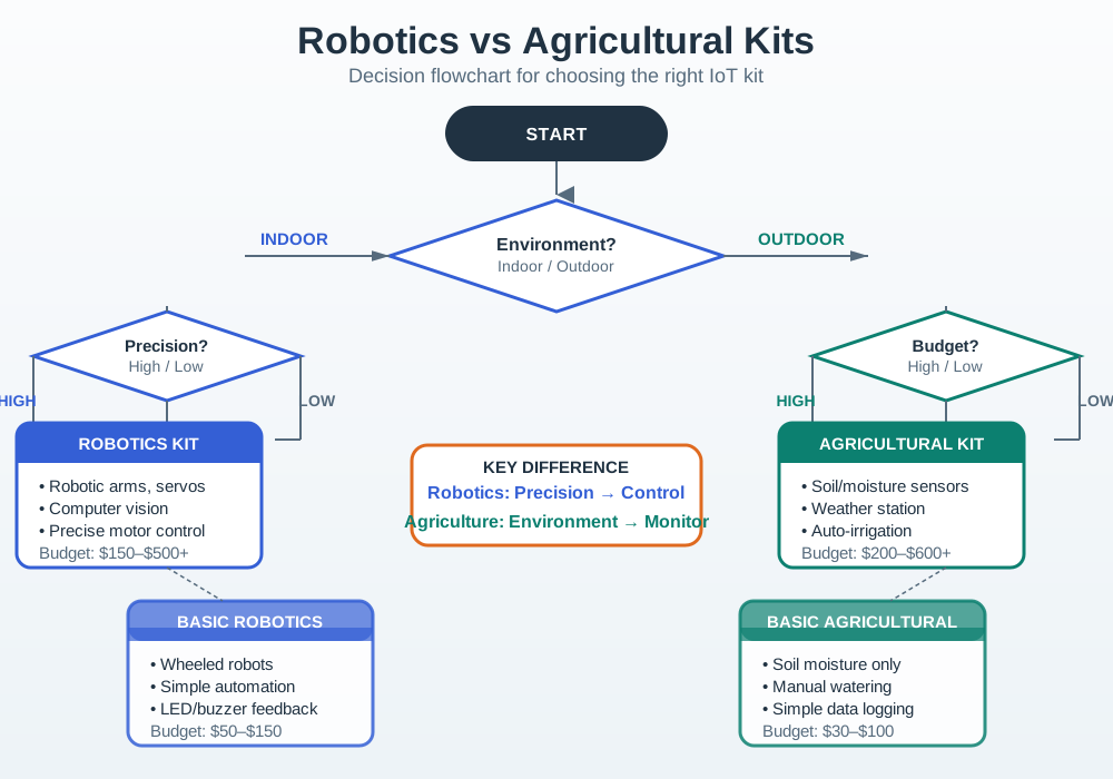
Choose the kit role that exposes the current risk. Do not compare a classroom robot, a mobile base, a field sensing node, and a site gateway by a single feature. They answer different review questions.
20.8 Robotics Kit Evidence
Robotics prototypes fail when motion is treated as a software problem only. The kit should expose mechanical, electrical, sensing, and control behavior together.
Review robotics evidence with these questions:
Record the route, surface, load, start state, stop condition, observed failure, and recovery action. A short motion log is more reviewable than a long video with no measured outcome.
20.9 Agricultural Kit Evidence
Agricultural prototypes fail when a bench sensor is assumed to represent a field sensor. The kit should expose placement, calibration, environmental variation, coverage, power rhythm, and maintenance effort.
Review field evidence with these questions:

Phoebe’s Why
An antenna cannot manufacture power – it can only redirect the power it is fed, concentrating it into a narrower angle the way an aperture focuses light in wave optics. That redirection is free in one specific sense: whichever end of the link gets the bigger, more directional antenna gains the same link-budget benefit whether the improvement happened at the battery-powered field node or at the mains-powered gateway. So a coverage evidence gap has two very different fixes with very different energy prices. Raising a field node’s own transmit power costs battery on every single uplink, forever. Raising the gateway’s receive-antenna gain instead buys the identical decibels of link margin without asking the field node’s battery for one extra milliwatt – which is exactly why “energy evidence” and “coverage evidence” belong on the same review record instead of being solved independently.
The Derivation
Effective radiated power combines transmit power and antenna gain:
\[\mathrm{EIRP(dBm)} = P_t\mathrm{(dBm)} + G\mathrm{(dBi)}\]
Gain and physical collecting aperture are the same fact in two units:
\[A_e = \frac{G\lambda^2}{4\pi}\]
A dB of link-budget gain can come from either side, but the energy cost differs by unit: antenna gain (dBi) costs nothing extra in transmit power, while matching the same dB purely with node transmit power means
\[\frac{P_2}{P_1} = 10^{\Delta(\mathrm{dB})/10}\]
– a power ratio, not a distance ratio, so it scales the node’s per-uplink energy \(E=P\times t\) directly.
Worked Numbers: Gateway Antenna Versus Node Power
The chapter’s kit list names Dragino/RAKwireless LoRaWAN field nodes and LoRaWAN gateways without fixing antenna gains, so take standard, catalog-typical figures: a \(2\) dBi stub antenna and EU868’s standard \(14\) dBm conducted power on the field node, and a gateway antenna upgraded from a \(3\) dBi omni whip to an \(8\) dBi panel.
- Gateway gain increase: \(\Delta G = 8 - 3 = 5\) dB of extra link margin, at zero extra field-node transmit energy.
- To buy that same 5 dB purely by raising the node’s own transmit power would require \(10^{5/10} = 3.16\times\) more power: from \(10^{14/10}=25.1\) mW up to \(25.1\times3.16 = 79.4\) mW (\(\approx19.0\) dBm) – likely past the regulatory cap, and tripling the node’s per-uplink transmit energy \(E=P\times t\) for every future message.
- Physical aperture, US915 (\(\lambda = c/f = 3.00\times10^{8}/915\times10^{6} = 0.328\) m): the 8 dBi gateway panel collects over \(A_e = 10^{8/10}\times0.328^2/4\pi = 0.0540\ \mathrm{m}^2\) – a realistic panel size for a fixed gateway mount.
That is the physical reason the “energy evidence” bullet above should be checked against the “coverage evidence” bullet before assuming a weak link means a bigger field-node battery: often the cheaper fix, in both dollars and milliamp-hours, sits at the gateway.
An outdoor reading is incomplete without placement notes. Record depth, shade, mounting, nearby water, cable route, last service, and weather conditions with the measurement.
20.10 Evidence Matrix
Use the matrix to decide which kit belongs in the current experiment and which evidence can wait until a later prototype form.
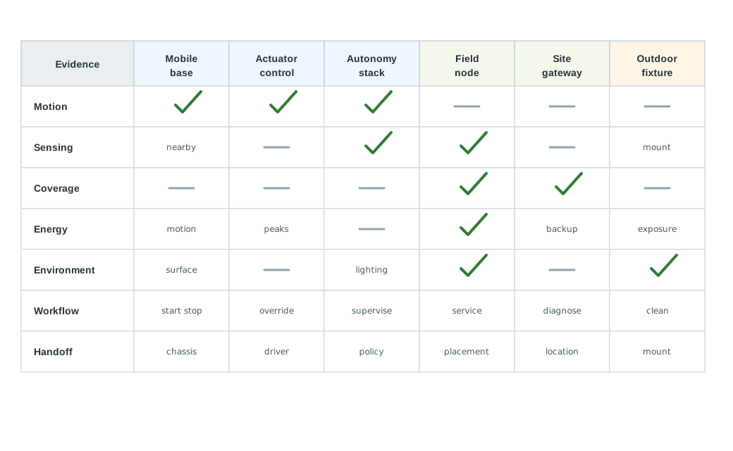
Use these review rules:
20.11 Greenhouse and Bed Monitor
A team is prototyping a greenhouse system. A small mobile scout should inspect rows and report blocked aisles, while fixed bed nodes should report soil and air conditions. The team stages evidence instead of building one large demonstration immediately.
20.11.1 Stage 1: Motion Evidence
The mobile base kit is tested on the greenhouse floor with representative turns, aisle widths, slopes, wet spots, payload, and stop conditions. The team records route repeatability, obstacle detection, safe stops, stuck conditions, and recovery actions.
20.11.2 Stage 2: Field Evidence
The field sensing nodes are placed in several beds. The team records placement depth, shade, irrigation exposure, local reference readings, battery state, message gaps, and maintenance notes.
20.11.3 Stage 3: Gateway Evidence
The site gateway kit is placed where a real gateway might be installed. The team records message buffering, clock alignment, stale-reading warnings, restart recovery, and local status indicators.
20.11.4 Stage 4: Integration Review
Only reviewed status messages are combined: scout observations, bed readings, gateway status, and stale-data flags. The next prototype can change chassis, enclosure, or mounting only with clear change conditions.
prototype=greenhouse-scout-and-bed-monitor
current_question=can mobile inspection and fixed bed sensing produce reviewable status together?
motion_evidence=route repeatability, obstacle stops, stuck recovery, payload effect
field_evidence=placement notes, local reference readings, irrigation exposure, service notes
gateway_evidence=buffering, stale-reading flags, restart recovery, local status
integration_boundary=kit boards prove subsystem evidence; next form must check chassis, enclosure, sensor placement, and gateway location again
rejected_option=single full-system demo because it hides motion and field failures
next_step=carrier fixture for field nodes plus mobile-base mount review
20.12 Integration Boundary
The kit proves evidence, not the final robot or field deployment. Draw a boundary before moving to a custom chassis, outdoor enclosure, production fixture, or site workflow.
20.13 Kit Review Record
Leave a record that another reviewer can challenge. A good record explains what the kit proved, what was rejected, what remains unproven, and when evidence must be repeated.
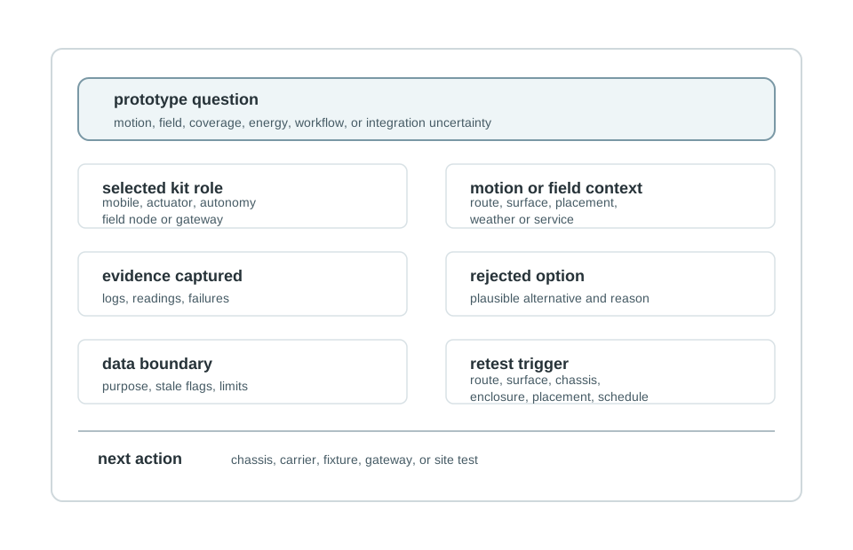
Use this template:
prototype=
stage=
current_question=
selected_kit_role=
motion_or_field_context=
evidence_captured=
rejected_option=
integration_boundary=
data_boundary=
change_condition=
next_action=
review_owner=
review_date=
20.14 Knowledge Check
20.15 Common Failure Patterns
20.16 Summary
- Robotics kits are strongest when they expose motion, sensing, control, power, safety, and recovery evidence.
- Agricultural kits are strongest when they expose placement, calibration, environment, coverage, energy, and maintenance evidence.
- Combined systems should stage motion evidence, field evidence, gateway evidence, and integration evidence separately.
- Kit evidence must be separated from final responsibilities such as chassis, outdoor enclosure, sensor mount, gateway location, data boundary, and service workflow.
- A clear review record makes the decision revisable when the prototype moves to a chassis revision, carrier board, outdoor fixture, or site trial.
20.17 Key Takeaway
Robotics and agricultural kits should be evaluated against environment, motion, sensing, power, connectivity, maintainability, and field-test constraints.
20.18 What’s Next
| If you want to… | Read this |
|---|---|
| Review kit selection across broader constraints | Kit Selection Guide |
| Compare smart-home and environmental kit evidence | Smart Home and Environmental Kits |
| Plan the move from kit evidence to board-level hardware decisions | Hardware Platform Selection for IoT Prototypes |