21 Industrial and Wearable Kits
Use harsh-environment and body-worn kits to collect evidence without confusing a kit demo with a product design
industrial IoT kit, wearable IoT kit, body-worn prototype, harsh-environment prototype, kit evidence

Phoebe’s Why
Two of this chapter’s “for handoff” items – antenna position and the field interface – share one physical idea: a fixed budget has to survive whatever the environment does to it. Antenna gain does not create power; it reshapes a fixed transmit power into a narrower beam, a good trade for an industrial gateway that is bolted to a cabinet and always pointed at the same access point, and a poor one for a wearable whose orientation on a moving body cannot be predicted, so it is normally kept close to isotropic instead. The chapter’s 4-20 mA pressure transducer solves a related problem for the wired side: a long, noisy cable run would corrupt a voltage signal by simple IR drop, but a current loop keeps the same current flowing at every point in the series circuit regardless of the wire’s resistance, so the signal survives the cable run that would defeat a naive voltage measurement.
The Derivation
Effective isotropic radiated power and the gain-versus-angle trade:
\[\mathrm{EIRP\,(dBm)} = P_t\,\mathrm{(dBm)} + G\,\mathrm{(dBi)}, \qquad G=\frac{4\pi}{\Omega}\]
Range scales with the antenna-gain difference between two designs at the same receiver sensitivity:
\[\frac{d_2}{d_1} = 10^{\Delta G_{dB}/20}\]
A series 4-20 mA current loop, by Kirchhoff’s current law, carries the same current \(I\) through every element regardless of cable resistance \(R_{cable}\):
\[V_{supply} \geq I\,(R_{cable} + R_{burden})\]
A plain voltage signal has no such immunity – the cable’s own resistance subtracts directly from the reading:
\[V_{measured} = V_{source} - I\,R_{cable}\]
Worked Numbers: A Fixed Gateway and a Body-Worn Radio
The chapter names antenna position and a 4-20 mA transducer but fixes no gain, cable length, or wire gauge, so take standard, catalog-typical figures.
- Industrial gateway, fixed and aimed at a known access point: 14 dBm module with a 6 dBi patch, \(\mathrm{EIRP}=20\) dBm
- Wearable radio, orientation unpredictable through a shift: 0 dBm BLE module with a near-isotropic 0 dBi chip antenna, \(\mathrm{EIRP}=0\) dBm
- Range advantage from the fixed antenna’s extra 20 dB: \(10^{20/20} = 10.0\times\) farther at the same receiver sensitivity – a trade only worth making because the gateway’s heading never changes
- 4-20 mA loop over a 500 m run of catalog-typical 24 AWG wire (0.0842 \(\Omega\)/m, round trip): \(R_{cable} = 0.0842\times500\times2 = 84.2\ \Omega\); with a 250 \(\Omega\) burden resistor at 20 mA full scale, \(V_{needed} = 0.020\times(84.2+250) = 6.68\) V, well inside a 24 V supply’s headroom
- Double the run to 1,000 m: \(R_{cable}=168\ \Omega\), \(V_{needed}=0.020\times(168+250)=8.37\) V – still compliant, and the current the far end reads is unchanged
- The same 20 mA flowing through that 168 \(\Omega\) cable resistance would corrupt a plain 0-10 V voltage signal by \(0.020\times168=3.37\) V – over a third of full scale, on a cable a current loop shrugs off
The antenna keep-out zone and the current-loop choice are answers to the same design question asked twice: what does this signal’s physical carrier do when the installation is not the clean bench it was demoed on?
21.1 Start With the Story
Industrial and wearable prototypes meet people, machines, and environments that do not forgive vague evidence. A wearable must respect body placement, comfort, privacy, battery life, and maintenance. An industrial kit must survive noise, safety expectations, physical access limits, and support ownership. The useful story begins with the person or process that must trust the result.
This chapter uses kits as controlled trials. Pick the kit that exposes the real context, capture measurements and workflow notes, and record which compliance, safety, or durability questions still require a stronger prototype.
21.2 Industrial vs Wearable Kit Risks
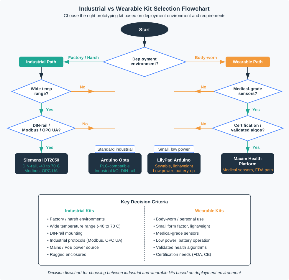
Industrial kits should expose site constraints: 24 V control power, isolated inputs, relay or transistor outputs, RS-485, CAN, Ethernet, Modbus, OPC UA, PLC or SCADA boundaries, cabinet mounting, cable strain, service access, and recovery after a noisy interruption. A kit that only works on a desk has not answered the industrial question.
Wearable kits should expose body constraints: placement, contact pressure, motion artifacts, sweat, comfort, charging rhythm, BLE pairing, phone permission limits, data minimization, and what the wearer sees when sensing fails. A kit that only streams clean data from a hand-held board has not answered the wearable question.
- Industrial question: can the prototype behave near the equipment, wiring, gateway, enclosure, and maintenance workflow it will meet later?
- Wearable question: can the prototype stay useful, comfortable, charged, private, and understandable while attached to a person?
- Shared question: which result survives the move to a carrier board, sealed enclosure, garment fixture, phone app, or field pilot?
For example, a pump-room monitor might start with an Arduino Opta, Siemens LOGO!, WAGO controller, or Moxa gateway because the risk is not simply reading a sensor. The team needs to know how 24 V control power, terminal blocks, relay outputs, Modbus RTU over RS-485, Ethernet, local status LEDs, cabinet clearance, and technician access behave near the real equipment. A successful desk demo is only the first clue. The useful industrial record says which site conditions were represented and which still need a cabinet or field fixture.
A wearable fatigue or safety prototype has a different evidence shape. A Nordic Thingy, nRF52840 Sense board, Movesense sensor, Shimmer kit, BMI270 IMU board, MAX30101 optical sensor, or textile fixture should be judged by placement, motion artifact, strap pressure, battery runtime, BLE reconnect, wearer feedback, cleaning, consent, and data minimization. The question is not whether the electronics can stream numbers. The question is whether the worn system can be used during a real shift without producing misleading data or an unacceptable burden.
21.3 Match Kit Families to Risk
Industrial experiments may use Arduino Portenta Machine Control, Arduino Opta, Siemens LOGO! or S7-1200 starter kits, WAGO controllers, Phoenix Contact PLCnext hardware, Beckhoff CX controllers, Advantech or Moxa edge gateways, Seeed reComputer Industrial systems, Raspberry Pi Compute Module carriers, or DIN-rail I/O modules. Wearable experiments may use Nordic nRF52840 or nRF5340 development kits, Nordic Thingy sensor platforms, Arduino Nano 33 BLE Sense, Adafruit Feather nRF52840 Sense, Seeed XIAO nRF52840 Sense, Movesense sensors, Shimmer sensing kits, SparkFun and Adafruit Qwiic/STEMMA QT sensor boards, MAX30101 or MAX86150 optical and ECG front ends, Bosch BMI270-class IMUs, and LiPo charger or fuel-gauge boards.
- For industrial fit: log supply voltage, input threshold, isolation boundary, relay or MOSFET load, terminal-block strain, enclosure clearance, DIN-rail access, protocol timing, gateway restart, and local fault indication.
- For wearable fit: log body location, strap or clip method, IMU motion artifact, PPG or ECG contact quality, skin temperature, sweat exposure, cleaning step, charge time, battery runtime, BLE reconnect, and wearer-facing failure cue.
- For the phone or gateway path: log BLE GATT characteristics, iOS CoreBluetooth or Android BLE permission state, background behavior, MQTT or HTTPS handoff, timestamp freshness, duplicate messages, dropped samples, and offline queue length.
- For handoff: mark which connector, board size, antenna position, battery, sensor package, enclosure, textile, firmware library, and compliance assumption is kit-only.
A practical industrial kit test should include the field interface, not just the controller. If the final device reads a 4-20 mA pressure transducer, an NPN proximity sensor, or an RS-485 Modbus meter, record the actual signal range, termination, shield connection, isolation boundary, poll interval, timeout behavior, and local fault indication. If the gateway publishes to MQTT or HTTPS, record topic or endpoint, payload timestamp, retained state or queue behavior, duplicate handling, offline duration, and recovery after power loss. These details make the result reviewable when the board or gateway changes.
A practical wearable kit test should include the body fixture and phone or hub path. Record strap position, orientation, attachment force if relevant, IMU axis mapping, PPG or ECG contact quality, cleaning step, charging contact behavior, BLE service ids, phone permission state, background reconnect, and the user-visible cue when sensing fails. A ten-minute lab run is not the same as a shift trial, but it can still expose whether the kit is worth carrying into a more realistic fixture.
21.4 Physical and Operational Failures
Industrial and wearable failures often happen outside the code path. Ground loops, ESD, surge, EMI, cable flex, connector reversal, regulator dropout, brownout recovery, ingress, washdown, glove use, and technician access can defeat a site prototype. Motion artifacts, loose contact, skin-tone effects, strap pressure, sweat, charging contacts, phone background limits, consent, and support handoff can defeat a wearable prototype.
- Electrical boundary: separate logic ground, field wiring, surge protection, fuses, TVS placement, opto-isolation, 4-20 mA loops, 0-10 V inputs, RS-485 termination, and CAN termination from the convenient dev-board wiring.
- Mechanical boundary: check gasket pressure, IP-rated enclosure assumptions, antenna keep-out, cable glands, strain relief, clip retention, textile routing, cleaning method, and repeated donning or removal.
- Operational boundary: verify provisioning, replacement, calibration, firmware update, rollback, local logs, support diagnostics, privacy notice, retention policy, and data deletion before a field trial.
- Integration boundary: test the exact message and state contract between body node, phone or hub, site gateway, dashboard, and supervisor workflow instead of relying on two separate demos.
The kit has done its job when it exposes which industrial, wearable, data, and service checks must repeat in the next product form.
Under the hood, industrial evidence depends on protection and diagnostics as much as sensing. A prototype that ignores TVS diodes, fusing, reverse-polarity protection, opto-isolation, terminal labeling, cable glands, watchdog behavior, and local status codes can pass a lab script and still be impossible to maintain. Wearable evidence has its own hidden limits: accelerometer axes rotate with the body, optical sensors need stable contact and light control, ECG electrodes need skin preparation and safe front-end design, and small batteries change behavior with charge age and temperature.
The integration boundary also carries data risk. A body node may collect more personal information than the gateway or supervisor workflow needs. A site gateway may combine location, worker id, shift time, hazard state, and equipment status in a way that requires purpose limits, retention limits, and access control. When moving beyond kits, the record should name the telemetry fields, processing location, retention rule, visibility rule, deletion path, and failure cue that must survive the next hardware form.
21.5 Learning Objectives
By the end of this chapter, you will be able to:
- Explain why industrial and wearable kits should be selected by evidence need, not brand familiarity.
- Compare harsh-environment evidence with body-worn evidence.
- Build a review matrix for interfaces, environment, form factor, energy, data handling, and handoff risk.
- Plan a combined site-and-worker prototype without hiding subsystem failures.
- Write a kit review record that preserves assumptions, rejected options, and change conditions.
21.6 Two Different Evidence Worlds
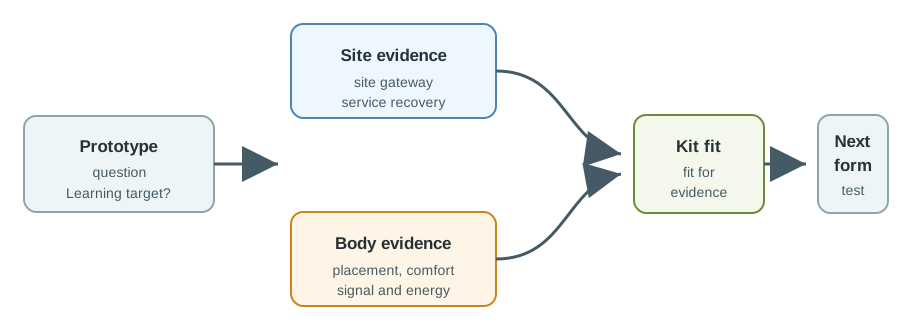
Industrial kits and wearable kits can both appear in the same IoT project, but they answer different questions. Industrial kits help a prototype survive site realities such as equipment interfaces, electrical noise, enclosure placement, service access, local gateway behavior, and maintenance workflow. Wearable kits help a prototype survive human realities such as body placement, motion, comfort, skin contact, charging rhythm, consent, and data minimization.
Start by naming the evidence gap:
An industrial gateway demo plus a body-worn sensor demo does not automatically prove a worker-facing system. Keep site evidence and body evidence separate until each has a reviewable record.
21.7 Kit Roles
Select the kit role that exposes the risk you need to review. A kit that is excellent for a cabinet-mounted gateway may be a poor fit for a worn node. A kit that is excellent for body-signal exploration may be a poor fit for dusty installation work.
21.8 Industrial Kit Evidence
Industrial prototypes often fail because the bench version did not represent the site. The kit should make the site risk visible: interfaces, mounting, enclosure, wiring, electrical environment, local recovery, and maintenance.
Review industrial kit evidence with these questions:
Feature lists rarely describe the actual cabinet, cable path, operator workflow, or maintenance constraint. A short site-oriented test log is more useful than a long kit comparison table.
21.9 Wearable Kit Evidence
Wearable prototypes fail when the electronics work but the body-worn system does not. The kit must help answer whether the sensing path, attachment method, energy rhythm, and data boundary make sense for a real person and a real workflow.
Review wearable kit evidence with these questions:
A wearable kit is not reviewed only on signal quality. It also needs evidence about donning, removal, comfort, cleaning, consent, failure indication, and what happens when a person uses it incorrectly.
21.10 Evidence Matrix
Industrial and wearable kits should be compared by the evidence they can produce. The same project may need both categories, but each should own a different part of the review.
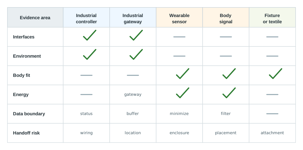
Use the matrix to avoid false comparisons:
21.11 Worked Scenario: Worker Safety Prototype
A team is prototyping a worker safety system for a noisy outdoor worksite. A body-worn device should detect motion and heat-stress indicators, and a site gateway should collect status summaries for supervisors. The team avoids a single all-in-one demo because it would hide both site and body risks.
21.11.1 Stage 1: Wearable Evidence
The wearable kit is tested in several body placements with realistic motion, clothing, and shift workflow. The team records signal quality, attachment stability, comfort notes, charging rhythm, cleaning steps, and visible failure indications.
21.11.2 Stage 2: Site Evidence
The industrial gateway kit is tested where it might be installed. The team records gateway placement, local status visibility, data buffering, network recovery, enclosure constraints, and how a technician would identify and recover common faults.
21.11.3 Stage 3: Integration Evidence
The team sends only a compact reviewed status message from the worn node to the gateway. This keeps the integration test focused on pairing, message timing, missing data, duplicate data, and recovery after interruption.
21.11.4 Stage 4: Handoff Review
The team decides which evidence can move forward and what must be checked again after the body-worn enclosure, attachment method, gateway enclosure, antenna position, and service workflow change.
prototype=worker-safety-monitor
current_question=can body-worn status and site gateway recovery work together?
wearable_evidence=placement notes, motion effects, comfort notes, charge rhythm, signal quality
site_evidence=gateway location, buffering, local status, network recovery, service access
integration_boundary=kit boards prove message path; next prototype must check enclosure, attachment, antenna, and shift workflow again
rejected_option=single all-in-one demo because it hides body placement and site recovery failures
next_step=carrier fixture for gateway plus worn enclosure mockup with repeatable attachment
21.12 Integration Boundary
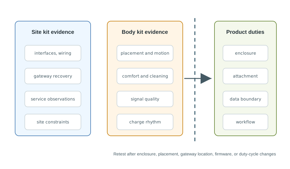
The kit proves evidence, not the final product. Draw a boundary before the team commits to enclosures, garments, gateway locations, or production workflow.
21.13 Kit Review Record
Leave a record that another reviewer can challenge. The record should show what the kit proved, what it did not prove, and what must be checked again.
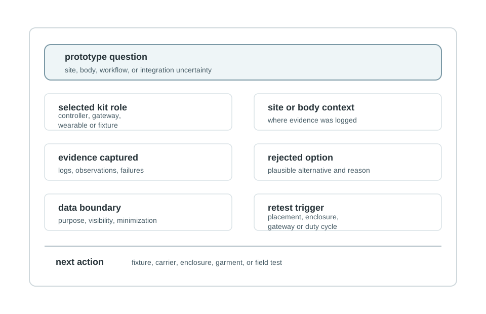
Use this template:
prototype=
stage=
current_question=
selected_kit_role=
site_or_body_context=
evidence_captured=
rejected_option=
integration_boundary=
data_boundary=
change_condition=
next_action=
review_owner=
review_date=
21.14 Knowledge Check
21.15 Common Failure Patterns
21.16 Summary
- Industrial kits are strongest when they expose site evidence: interfaces, environment, gateway recovery, service access, and installation assumptions.
- Wearable kits are strongest when they expose body evidence: placement, comfort, motion effects, energy rhythm, data boundaries, and human workflow.
- Combined worker-facing systems should stage wearable evidence, site evidence, and integration evidence separately.
- Kit evidence must be separated from final product responsibilities such as enclosure, garment, antenna, service process, and data policy.
- A review record makes the decision revisable when the prototype moves to a carrier, fixture, enclosure mockup, garment prototype, or field trial.
21.17 Key Takeaway
Industrial and wearable kits need extra scrutiny for enclosure, safety, durability, provisioning, maintenance, and user context before their demo value becomes design evidence.
21.18 What’s Next
| If you want to… | Read this |
|---|---|
| Compare specialized kits for robotics and agricultural prototypes | Robotics and Agricultural Kits |
| Review kit selection across broader constraints | Kit Selection Guide |
| Plan the move from kit evidence to board-level hardware decisions | Hardware Platform Selection for IoT Prototypes |