24 Smart Parking Sensor Contracts
More
Depth: Practitioner
Progress saves as you read. Mark sections complete as you go; your progress appears in the sidebar.
- Podcast audio coming soon
- Character narration audio coming soon
24.1 Follow One Bay from Sensor to Driver
Smart parking needs an evidence chain from the physical bay to the driver’s decision. This chapter follows a city’s in-ground parking sensor to ask what each reading proves, how calibration separates neighbouring vehicles, and how the service recovers when a message is lost.
Picture a driver sent to an empty-looking bay that is in fact blocked. One wrong reading can waste time and trust. The system must establish how it sensed the car, how sure it was, when the result was sent, and what happened when no new message arrived. The city is trying to manage curbside demand; the driver needs a space that is actually usable.
A magnetometer measures a nearby magnetic field. A vehicle bends that field, but so can a car in the next bay. LoRaWAN, short for Long Range Wide Area Network, is a low-power radio network for small messages over long ranges. It carries the bay’s free or occupied state, but a missing message can leave the driver’s map stale.
Lessons from Real Deployments: Barcelona Smart City reads Barcelona’s deployment as evidence. Its companion, Volkswagen Predictive Maintenance and Cross-Case Lessons, compares that with industrial predictive maintenance. Here we examine the sensor contract inside the Barcelona parking story: sensing physics, link behavior, calibration, workflow evidence and measured user outcome must remain connected.
The problem is to preserve that connection through interference, uncertainty and silence. We will first trace the service, then calibrate the bay, pair efficient change reporting with recovery, and specify the records needed before rollout expands. Copying visible technology without those records cannot establish that another city’s result will transfer.
KEY CONCEPTS
- Occupancy evidence
A magnetic field change needs a local empty-bay reference.
- Crosstalk calibration
Separate this bay’s occupant from the neighbour’s vehicle.
- Recovery heartbeat
Resend current state so a lost transition can be repaired.
- Rollout record
Retain sensor, network, workflow and outcome evidence.
24.2 Learning Objectives
After this page, you should be able to:
- Explain how a magnetometer detects vehicle occupancy by measuring local magnetic-field distortion.
- Identify why adjacent-bay vehicles create false positives and how per-sensor baselines and thresholds reduce crosstalk.
- Describe why event-driven LoRaWAN reporting saves battery but needs a recovery heartbeat.
- List the field metadata needed to scale a parking deployment without guessing.
- Read Barcelona-style smart-city deployments as evidence chains rather than success stories.
24.3 Trace Occupancy Through the Service
Inspect the physical sensor in Figure 1.1 before following its reading.

A city puts an in-ground sensor in each parking bay to report whether it is occupied, feeding a “find a free space” app. The sensor detects a car with a magnetometer: a parked vehicle’s steel body distorts the Earth’s magnetic field, about 25-65 microtesla, at the sensor, and that change signals occupancy. Occupancy state is reported over LoRaWAN because it offers long range, low power, and acceptable underground performance in the bay housing.
To see how small the field-sensing part really is, look at the breakout board in Figure 1.2.

Start at the small black package in the middle of the red board. That package contains the field-sensitive element and associated circuitry, which produce a voltage with no moving parts. Follow the short tracks to the row of pads along the edge, marked for power, output, filter, and ground. The board hands the rest of the system one analogue reading and nothing else. The board’s mounting holes show that installation is part of the measurement: how a sensor is fixed determines the field it sees. Figure 1.2 illustrates field-to-voltage sensing; it does not establish parking-bay suitability. Baselines and neighbour-bay tests still have to do that.
The mechanism sounds simple but hides a real engineering problem the case must confront: a magnetometer cannot see a bay’s boundary, only a magnetic field, and cars in neighbouring bays distort that field too.
The map in Figure 1.3 shows how far an occupancy reading has to travel before it can support any city-level claim.
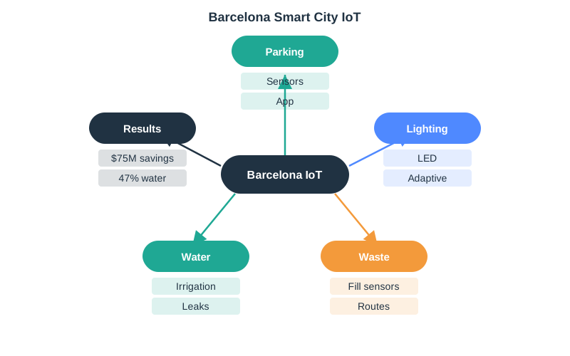
Read the four numbered bands downward. Band one puts parking beside lighting, waste, and water, so the bay sensor is one feed among several. Band two shows why that matters: all four report into one shared platform that keeps the source and the time of each event, which is what lets a department judge whether a reading is still fresh. Band three turns that state into work, either a dispatch decision or a public app screen. Band four lists the claims people actually want, such as shorter search time and less traffic, then marks the boundary. One occupancy event does not prove any of them. Figure 1.3 is the chain this chapter asks you to copy.
Read the Barcelona and Volkswagen cases as evidence chains rather than success stories. The case evidence starts with a field condition, such as parking occupancy or robot vibration, then follows the path through sensing, communication, edge processing, workflow integration, user adoption, and measured operating result. A deployment lesson is transferable only when that whole chain is visible. Otherwise a team may copy the most visible technology, such as LoRaWAN, edge gateways, or a dashboard, while missing the calibration, maintenance, trust-building, and integration work that made the deployment useful.
That framing also separates local context from reusable pattern. Barcelona’s service mix, public procurement, and municipal data-sharing constraints are city-specific; Volkswagen’s robot fleet, production takt time, and maintenance culture are factory-specific. The reusable pattern is the disciplined loop: define the operating decision, instrument the right point, preserve uncertainty, connect the result to work, and measure whether people actually change behavior.
The NPTEL parking model divides the service into three functional layers. Information collection obtains occupancy from sensors, parking meters, sensor networks, or crowd sensing. System deployment manages the software system, parking information, guidance, and analytics. Service dissemination turns that managed state into infrastructure-based or infrastructure-free information, parking choices, pricing, and vehicle-facing activity. This split is useful because a trustworthy sensor reading can still become a poor service if deployment state is stale or dissemination sends a driver to the wrong place.
The same source distinguishes stationary sensing, which places many sensors to detect presence or absence in place, from mobile sensing, which uses fewer sensors to collect information along a route. That is not merely an installation choice. It changes what the evidence means.
The sensing choice therefore changes the record that the service must retain. A stationary record can bind one calibrated sensor, one bay, and one occupancy state, but it must expose neighbour-bay interference and failed-node coverage. A mobile record samples spaces along a route, so it must preserve route, observation time, revisit interval, and the spaces that were not observed. In either mode, shorter search time, less traffic and pollution, lower fuel use, greater mobility, and more parked-time revenue are service claims downstream of the three layers; they are not proved by an occupancy event alone.
24.4 Calibrate This Bay Against Its Neighbours
The service chain now returns us to its first decision: whether this bay is occupied.
Because the magnetometer measures a field, not a boundary, a large vehicle in an adjacent bay can distort the field enough to look like an occupant, creating a false positive that tells drivers a free bay is taken. This cross-detection is the defining real-world challenge of magnetic parking sensors, so the deployment must establish a calibration margin for each bay.
Each sensor learns its own empty-bay baseline field and flags occupancy only when the local change exceeds a threshold set above the crosstalk a neighbour’s car produces. The direct occupant shifts the field by a large amount, several microtesla or more close up. A neighbour’s car produces a smaller shift that the threshold rejects.
| Source | Field change at sensor | Decision |
|---|---|---|
| Empty bay | Roughly baseline, for example 50 microtesla | Vacant |
| Car in this bay | Large local shift | Occupied |
| Car in adjacent bay | Small shift, or crosstalk | Reject, below threshold |
Worked example. A sensor calibrated to a 50 microtesla baseline sees a 12 microtesla swing when a car parks directly over it, but only a 3 microtesla swing from a truck in the next bay. Setting the occupancy threshold at 6 microtesla catches the real occupant and rejects the neighbour. Where bays are tight or vehicles huge, a single magnetometer’s margin shrinks, and designs add a second sensing mode, such as radar, or fuse two axes of the magnetic reading to separate “above me” from “beside me.”
Test one bay while it is empty. Park a small car, a large car, and a car in the next bay. Save the raw change each time and tune the rule from those site facts. Then remove the car and prove that the bay returns to free.
A Hall junction gives . With a 1.00 mA bias, 10 micrometre InSb film, and 12.0 microtesla field swing, the raw signal is only 0.375 microvolts. Reaching a 10.0 mV comparator target therefore needs about 26,700 times voltage gain, or 88.5 dB. This is why the example requires a stabilized analogue chain with low-noise amplification and offset control before a microcontroller can classify occupancy; a bare junction wired to a GPIO is insufficient.
The amplifier changes the electrical signal, not the magnetic field. The 12, 3 and roughly 50 microtesla values describe conditions at the sensor. The worked comparison also gives copper a much smaller Hall coefficient than InSb for these dimensions; changing material does not remove the need to control noise.

24.5 Recover a State That Never Arrived
Calibration establishes what the sensor saw. The next problem is whether that state reached the app.
To pursue a multi-year battery target on LoRaWAN, the sensor reports on state change rather than streaming periodically: it sends a message when a bay transitions between vacant and occupied. This reduces airtime because a bay may change only a few times a day. In EU868, the applicable duty-cycle or channel-access constraint depends on the sub-band, device, and network configuration; 1% is a common case, not a universal LoRaWAN limit. Event-driven reporting still has a specific failure mode: an uplink may be configured as confirmed or unconfirmed, but either can ultimately be lost after interference or exhausted retries. If the only “now occupied” message is lost, the app shows the bay free until a later update.
The engineering answer is a periodic heartbeat: alongside change events, the sensor sends its current state on a slow schedule, such as every few hours, so a lost transition self-corrects at the next heartbeat, and the server can also detect a dead sensor by its silence. This is the classic event-driven trade-off: events give efficiency, heartbeats give recoverability. Getting the balance right is what makes the deployment trustworthy rather than merely cheap.
Worked example. A car leaves a bay and the sensor’s “vacant” uplink is lost to interference. With pure event reporting the app wrongly shows the bay occupied for hours, sending drivers past an empty space. Add a 4-hour heartbeat with a delivery policy that retries or otherwise confirms each heartbeat within the service target, and the next successfully delivered beat restores the true state. The four-hour interval bounds stale-state error only under that delivery assumption; a lost heartbeat extends the error to the next successful update. The same heartbeat lets the backend flag a sensor that has gone silent for a day as failed. The transferable decision from this case, pairing change-events with a recovery heartbeat and an explicit delivery assumption, applies to any lossy, low-power, event-driven IoT link.
Cut the radio path and verify that the map does not show an old state as fresh. Wait for the next heartbeat, record when the site marks the sensor as lost, and establish how a worker finds the right bay.
24.6 Keep the Evidence Needed for Rollout
A recoverable message still needs enough context for an operator to explain it.
For practitioners, the case-study question is what must be recorded before rollout expands. Parking sensors need installation depth, bay geometry, empty-baseline sample, adjacent-vehicle test result, firmware version, LoRaWAN spreading factor, gateway RSSI/SNR, battery estimate, and complaint history. Volkswagen’s maintenance case needs the same discipline in a factory form: robot asset id, sensor placement, model version, confidence threshold, technician acknowledgement, work-order outcome, and false-positive review. Those records let teams tune thresholds without guessing and separate a weak sensor, weak model, weak network, or weak workflow.
The backend should treat every parking or maintenance event as a state update with evidence attached. A parking message should include device id, bay id, sequence number, measured field delta, threshold version, battery, RSSI/SNR, gateway id, event timestamp, and whether the message is a change event or heartbeat. A maintenance alert should carry the sensor window, feature vector version, model id, confidence, asset state, and work-order link. That metadata is what lets operators reconcile stale app state, missed messages, and ignored alerts after the fact.
Here RSSI means received signal strength indicator, and SNR means signal-to-noise ratio. Keep these link measurements with the spreading factor and gateway identity so the rollout record includes the installed radio path.
Check the driver view too. A bay state needs a time and a clear source. If trust is low, guide the driver to another bay or mark the space as unknown. The contract must define what happens when the sensor, network or payment context is wrong, rather than turning doubt into a firm “free” claim.
24.7 Summary
A parking reading becomes useful guidance only when sensing, communication, workflow and user outcomes remain connected. Per-sensor baselines and adjacent-vehicle tests establish the occupancy threshold. Change events conserve airtime, while successfully delivered heartbeats repair stale state and silence rules identify failed sensors. Installation and message records let operators distinguish sensing, network and workflow failures before expanding the deployment.
Keep the evidence behind every “free” claim: a calibrated bay, a current delivered state and an explicit recovery rule. An occupancy event alone cannot prove a city-level benefit.
Next, compare this city evidence chain with Volkswagen Predictive Maintenance and Cross-Case Lessons.