25 Industrial Protocols: Selection and Security
More
Depth: Practitioner
Progress saves as you read. Mark sections complete as you go; your progress appears in the sidebar.
- Podcast audio coming soon
- Character narration audio coming soon
25.1 Choose a Stack the Plant Can Support
Industrial protocol selection turns timing requirements into a justified choice across installed equipment, traffic, recovery, and security. This is part 2 of 2; Industrial Protocols: Families and Timing supplies the protocol families and timing calculations behind the decision.
Consider the beverage company upgrading an older bottling line. Its sensors and actuators use Modbus RTU over RS-485 to reach a legacy programmable logic controller (PLC). The team wants predictive maintenance sensors, manufacturing execution system (MES) integration, and a cloud dashboard for remote monitoring. Work must fit planned maintenance windows, and the limited budget makes unnecessary device replacement a poor choice.
The problem is to add those capabilities while keeping the existing filling and capping sequence dependable. Operational technology (OT) controls the physical process; information technology (IT) supports enterprise information systems. Their traffic has different timing and security duties. We will select the machine-control path first, compare the evidence, and then define the OT/IT crossing. The result is a selection record that explains both the protocol stack and its boundaries. A demilitarized zone (DMZ) supplies a controlled crossing for the required enterprise exchange.
KEY CONCEPTS
- Timing budget
Choose the control path from cycle time and determinism.
- Brownfield fit
Retain working segments until replacement is justified.
- Controlled crossing
Keep enterprise access behind the industrial DMZ.
- Selection evidence
Record traffic, recovery, safety and lifecycle duties.
25.2 Learning Objectives
By the end of this chapter, you will be able to:
- select an industrial protocol from timing and system duties
- compare candidates with explicit decision evidence
- define OT-IT security boundaries for the selected path
25.3 Start With the Control Loop
Choose the deterministic control path first, then add only the safety, legacy, and integration layers the plant needs. Determinism means meeting the required timing bounds; a fast link alone does not establish it. Figure 1 puts that timing decision ahead of integration convenience.
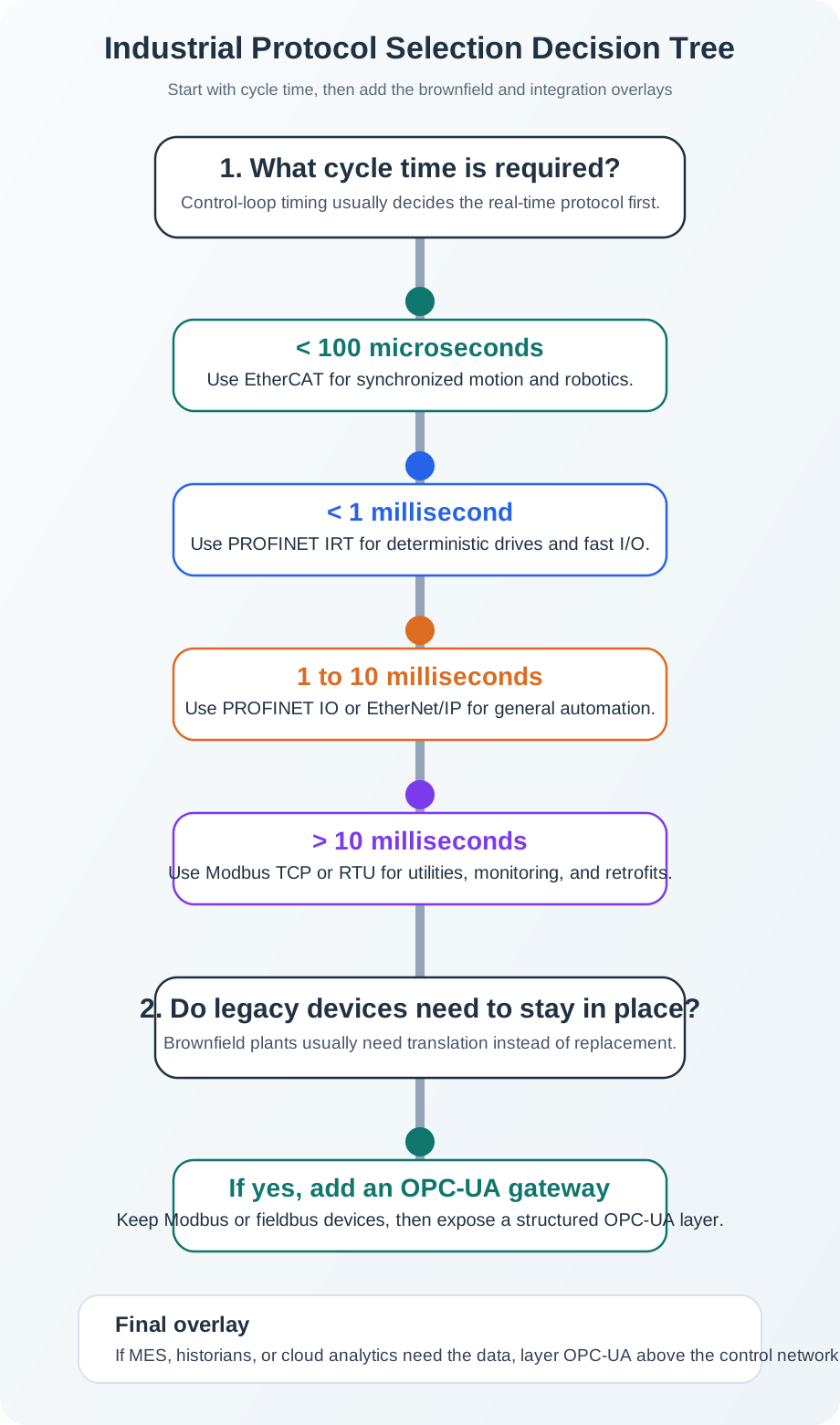
Start Figure 1 with cycle time. Motion below 100 μs points to EtherCAT; work below one millisecond can fit Process Field Network (PROFINET) IRT; a sub-10-ms factory loop can use PROFINET IO or a suitable EtherNet/IP path, while monitoring may need only Modbus TCP. Then apply plant constraints as overlays. An OPC UA gateway can retain legacy devices, OPC UA can carry checked context toward IT, and PROFIsafe or FSoE adds a safety-rated layer. The final stack keeps deterministic control near the machine and separates it from the integration path upward.
A credible selection record states the required cycle time, safety role, device count, legacy constraints, and IT or cloud priority before naming the stack. Modern systems often layer EtherCAT or PROFINET for real-time control, OPC UA for IT integration, MQTT over TLS for cloud connectivity, and protocol gateways for legacy devices. Each layer needs an explicit duty; the integration path does not inherit the control path’s timing guarantees.
25.4 Compare Candidates Against Installed Equipment
The comparison below supplies a starting point for the selection record. Its dates, speeds and cycle times describe the chapter’s reference cases, rather than universal limits for every device or operating mode. Qualitative determinism and security labels are qualitative comparisons, not guarantees, and require evidence from the chosen equipment and configuration. In particular, a “Good” security label does not mean that a legacy industrial protocol authenticates or encrypts its traffic.
| Protocol | Year | Reference maximum speed | Reference cycle time | Determinism | Qualitative security rating |
|---|---|---|---|---|---|
| Modbus | 1979 | 10 Mbps | 100 ms+ | None | None |
| PROFIBUS | 1989 | 12 Mbps | 10 ms | Good | Basic |
| PROFINET | 2003 | 100 Mbps | <1 ms | Excellent | Good |
| EtherNet/IP | 2001 | 1 Gbps | 1–10 ms | Good | Good |
| EtherCAT | 2003 | 100 Mbps | <100 μs | Excellent | Good |
| OPC UA | 2008 | 1 Gbps+ | Variable | Configurable | Excellent |
Modbus fits simple monitoring and basic machine control. Check the job’s timing and stale-data requirements before accepting this fit.
Read these comparison values alongside the installed equipment and communication path. A working Modbus segment may remain useful when replacement would add downtime without a demonstrated need. A gateway can expose its data through OPC UA for operations systems. Keep enterprise access behind the industrial DMZ, and test stale-data behavior before relying on the reporting path.
PROFIBUS fits process automation and legacy European plants. Existing equipment and support needs belong in the selection record alongside timing.
A working PROFIBUS segment may be worth retaining when replacement adds downtime and validation risk. Inventory the installed devices before deciding whether a gateway, proxy, or segmented retrofit is enough. The security rating still requires an architecture with defined zones and allowed communication paths. Keep enterprise connections behind the industrial DMZ and control engineering access.
PROFINET fits general factory automation and Siemens ecosystems.
EtherNet/IP fits discrete manufacturing and Rockwell-heavy plants. Vendor ecosystem fit belongs alongside timing and recovery requirements in the selection record.
A suitable EtherNet/IP path can serve factory I/O cycles, but the complete path still needs evidence under traffic and recovery conditions. Record the required cycle time, device count, and safety role before accepting the comparison as a fit. Keep control near the machine and carry checked context upward through a separate integration layer with a controlled OT/IT boundary.
EtherCAT fits motion control, robotics, and synchronized axes. These duties make timing and synchronization central to the selection.
The chapter points to EtherCAT for motion below 100 μs, while requiring a justified choice across traffic, recovery, and installed equipment. Record the timing budget and safety role before selecting the stack. A safety-rated function needs an appropriate safety layer, such as FSoE. Keep deterministic control near the machine, with checked context moving separately toward operations and enterprise systems through a controlled boundary.
OPC UA fits IT/OT integration, historians, and cloud-facing interoperability.
Read these ratings alongside the system duties. The selection record should establish timing requirements before choosing the integration path. Deterministic control stays near the machine, while OPC UA carries checked context toward operations and IT systems. An OPC UA gateway can also retain legacy devices. The security rating still requires a controlled boundary: enterprise and internet traffic must pass through the industrial DMZ rather than connect directly to process-control levels.
For the bottling line, these comparisons support a proportionate upgrade: first test whether the condition sensors need to join a control loop or only supply maintenance information. A vendor ecosystem can narrow supported choices, but it cannot substitute for timing, stale-data and recovery evidence.
25.5 Place Each Duty in the Plant
With the protocol route chosen, place it inside the plant architecture. Industrial IoT (IIoT) connects OT with IT for production monitoring, quality control and supply-chain visibility while preserving shop-floor reliability. Figure 2 organizes field devices, controllers, supervisory control and data acquisition (SCADA), MES and enterprise analytics into distinct layers aligned with ISA-95.
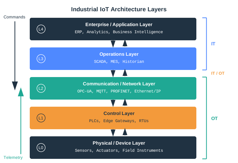
Read the levels in Figure 2 from the bottom up. Sensors, valves and motors act on the process, and the controllers just above them close loops in about a millisecond, so that control traffic stays on a fieldbus and never leaves the plant floor. Move up and the job changes from control to record keeping: the operations reporting path collects status, alarms and checked context. The band near the top marks the controlled crossing. Enterprise traffic is not allowed to reach the control levels directly. It is brokered through a controlled crossing, with engineering access logged and limited. The two worked paths at the foot of the figure give the practical test: a slow monitoring trend can afford that detour, a drive loop cannot.
A historian stores process history; MES supports production operations. Real-Time Requirements and ISA-95 develops the timing and automation hierarchy used here. The OPC UA Standard chapter explains the structured interoperability layer carrying checked context between these systems.
25.6 Define and Defend the OT/IT Crossing
Connecting IT to OT creates remote paths to systems that previously required physical access. The Ukraine power grid attacks illustrate why remote access, engineering workstations, credentials and SCADA operations need industrial-specific segmentation and monitoring. The bottling line’s cloud dashboard therefore needs a controlled reporting path with no direct access to process control.
The following comparison captures common planning assumptions, not fixed rules for every installation. Preserve the actual site’s availability and maintenance requirements in the decision record.
| Aspect | IT Security | OT Security |
|---|---|---|
| Primary goal | Confidentiality first | Availability first |
| Acceptable downtime | Hours for maintenance | Zero unplanned downtime as a production goal |
| Patch frequency | Monthly or more often | Annually or less (scheduled shutdowns) |
| System lifespan | 3-5 years | 15-30 years |
| Network isolation | Connected to internet | Historically air-gapped |
| Authentication | Strong passwords, MFA | Often none, shared credentials |
| Encryption | Standard practice | May disrupt timing or compatibility; validate before deployment |
| Vendor support | Ongoing updates | May be end-of-life |
Applying office IT practices directly to OT can disrupt time-sensitive systems; leaving OT unchanged can expose weak protocols and long-lived credentials. Protocol exploitation, patch constraints and shared accounts need compensating controls as well as a perimeter.
Attack vectors with industrial consequences:
-
Protocol exploitation: Industrial protocols (Modbus, PROFINET, EtherCAT) were designed for reliability, not security. Many lack authentication entirely.
-
Legacy system vulnerabilities: Long-lived PLCs, HMIs, engineering stations, and operating systems may have patch constraints that must be handled through segmentation, compensating controls, and maintenance windows.
-
Physical process manipulation: OT attacks can cause physical harm (explosions, spills, equipment destruction, product contamination).
-
Supply chain compromise: Compromised firmware, engineering tools, libraries, or vendor update channels can bypass perimeter assumptions and must be controlled through verification and change management.
-
Insider threat amplified: Shared OT credentials complicate attribution when incidents occur; individual remote-access logs and physical or personnel controls can help identify operators.
Notable OT Security Incident Patterns:
| Pattern | Example families | Design lesson |
|---|---|---|
| Engineering workstation compromise | PLC logic manipulation campaigns | Protect project files, programming tools, and controller write paths |
| IT-to-OT pivot | Power-grid and manufacturing incidents | Keep enterprise access out of control zones without a managed DMZ path |
| Safety-system targeting | SIS-focused malware families | Separate safety functions, validate changes, and monitor engineering access |
| Ransomware affecting operations | Industrial ransomware events | Segment backups, remote access, identity, and production dependencies |
| Credential or remote-access abuse | VPN and vendor-access incidents | Enforce MFA, least privilege, session logging, and approved jump paths |
The Purdue reference hierarchy is commonly used with ISA-95 functional levels and International Electrotechnical Commission (IEC) 62443 security practices. These are related frameworks, rather than one interchangeable standard. The table includes Levels 0–5 and the conventional industrial DMZ at 3.5; cloud hosting itself does not assign an ISA-95 level.
| Level | Name | Examples | Security Focus |
|---|---|---|---|
| 0 | Physical Process | Sensors, actuators, valves | Physical security, tamper detection |
| 1 | Basic Control | PLCs, RTUs, DCS controllers | Firmware integrity, secure boot |
| 2 | Area Supervisory | SCADA, HMI, engineering workstations | Access control, network segmentation |
| 3 | Site Operations | Historians, MES, batch management | Demilitarized zone (DMZ), monitoring |
| 3.5 | Industrial DMZ | Jump servers, data diodes | Strict access control, inspection |
| 4 | Enterprise | ERP, email, office IT | Standard IT security practices |
| 5 | External | Cloud, internet, remote access | Perimeter security, zero trust |
Critical Principle: Never allow direct connections between Levels 4-5 (IT/internet) and Levels 0-2 (process control). All traffic must traverse the Industrial DMZ (Level 3.5).
The industrial DMZ is the controlled crossing between enterprise IT and OT. It provides managed services and jump paths, inspection, logging and strict allow lists. Complete isolation would block the required exchange, while a shared office/control policy would ignore their different availability and maintenance needs.
Segment the bottling plant by function and criticality, then define its zones and allowed crossings:
-
Zone-based architecture: Group devices by function and criticality (safety systems separate from production, production separate from quality systems)
-
Conduit control: Define specific allowed communication paths between zones with explicit protocol and port restrictions
-
Unidirectional gateways (data diodes): For highest-security zones, use hardware that physically prevents traffic from flowing backward into OT
-
East-west traffic inspection: Even within zones, monitor lateral movement using OT-aware intrusion detection
Security evidence includes asset inventory, traffic baselines, zone and conduit rules, certificate and account ownership, patch windows, logging, rollback and incident-response practice. These records make the boundary reviewable when remote access or engineering tools change.
Phase 1 (Months 1-6): Visibility and Baseline
- Asset inventory: Discover all OT devices on the network
- Network mapping: Understand current traffic flows and connections
- Risk assessment: Identify highest-risk systems and connections
- Quick wins: Disable unnecessary services, segment obvious risks
Phase 2 (Months 7-18): Segmentation and Monitoring
- Implement Industrial DMZ between IT and OT
- Deploy OT-aware network monitoring
- Establish baseline behaviors for anomaly detection
- Develop OT-specific incident response procedures
Phase 3 (Months 19-36): Hardening and Governance
- Implement role-based access control
- Establish patch management program
- Conduct tabletop exercises and red team assessments
- Achieve IEC 62443 certification for critical systems
The schedule is a staged roadmap. Treat security as a foundation for the required Industry 4.0 exchange, and fit changes to approved operational windows.
25.7 Keep Monitoring Separate From Control
The boundary becomes concrete when tracing the bottling line’s condition-monitoring data. Figure 3 shows how modern monitoring can aggregate thousands of sensors for equipment health, production rates and energy consumption, with historical trends for optimization.
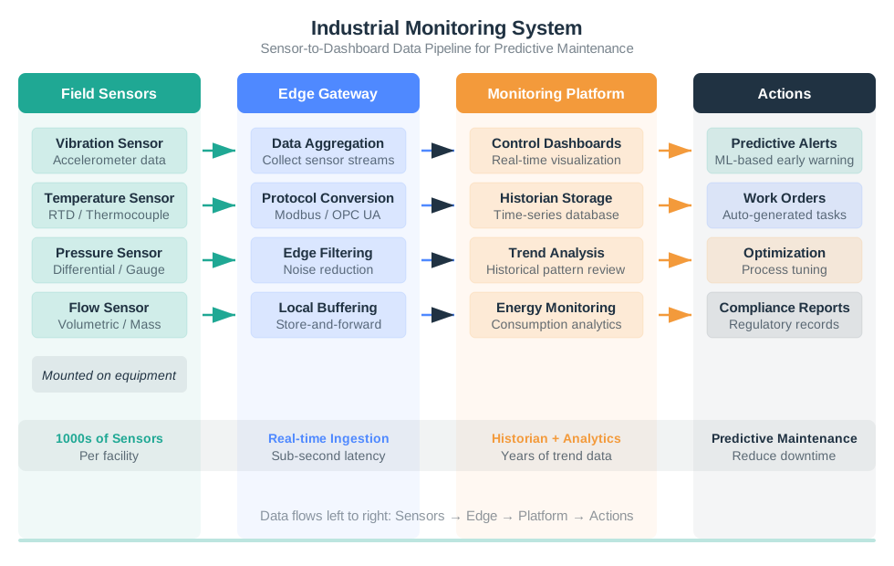
Figure 3 has three numbered stages, and the boundary sits between the second and third. Vibration, temperature, pressure and flow readings come off equipment on the plant floor, where the timing rules from earlier in this chapter apply. The edge stage collects and combines them, and that is the last point still inside the operations zone. Only summarised data crosses into the third stage, which splits into a live dashboard and a store of past trends. No arrow returns from monitoring to the equipment. This is an observation chain, so it can accept ordinary network delay and still be useful, which is why it is the safe kind of traffic to carry across the boundary.
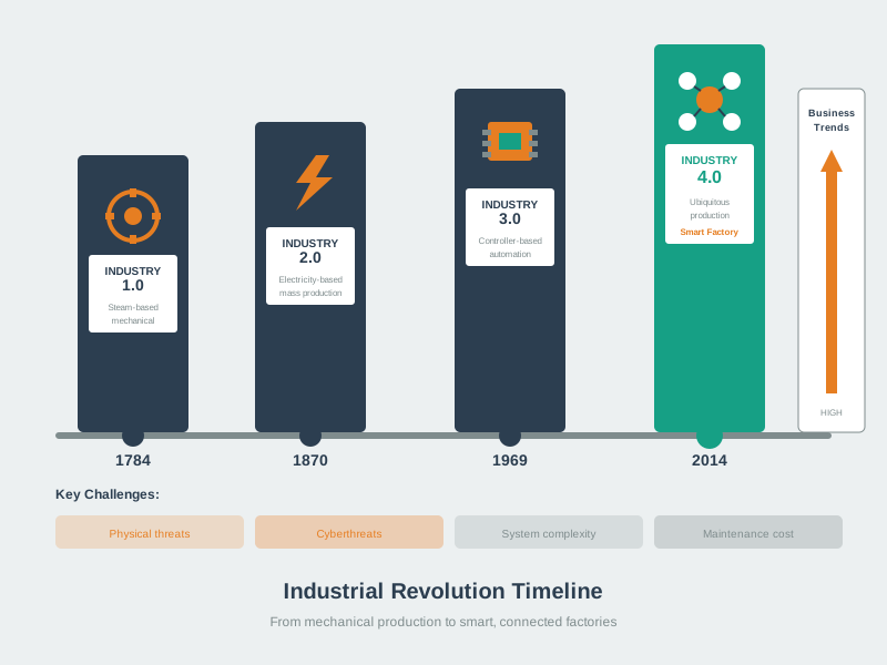
The sensor, controller, valve or motor, and process form a feedback loop of about 1 ms on the plant floor. The vibration sensor takes a different route: an edge check keeps high-rate samples local and sends checked alerts or summaries upward. OPC UA links that monitoring path to the MES or historian; MQTT over TLS carries summary data to the cloud dashboard. No monitoring arrow returns to the equipment. This separation matters when choosing a protocol and trust boundary: the dashboard may inform maintenance, but it is not the controller for the fast loop. The “connected factory” label joins the two duties without giving them the same timing or authority.
MQTT, REST and cloud APIs can support integration, but drive, I/O, interlock and motion traffic still need a deterministic fieldbus or industrial Ethernet path. Keep the real-time loop inside the cell or line and send checked context upward. Predictive Maintenance develops the condition-monitoring duty; Industry 4.0 Fundamentals places it in the broader IIoT operating loop.
25.8 Record the Bottling-Line Decision
Return to the beverage company’s maintenance windows and limited budget. Keep the working Modbus RTU segments connected to the existing PLC while testing the new predictive-maintenance, MES and remote-monitoring paths. The decision needs evidence at each step.
Step 1: Analyze timing requirements by device layer
- Existing bottle sensors/actuators: adequate for the current filling and capping sequence — no immediate need to replace
- New vibration sensors: high-rate sampling locally, but only quality-checked alerts and summaries need to cross into operations systems
- MES integration: Seconds to minutes for production counts, batch tracking
Step 2: Map requirements to protocol layers
| Layer | Current | Upgrade To | Justification |
|---|---|---|---|
| L0-L1 (bottle line) | Modbus RTU | Keep Modbus RTU | Working segment; replacement cost and downtime are not yet justified |
| L1 (condition sensors) | None | EtherCAT or PROFINET | Choose by whether sensors join the control loop or only report machine health |
| L2 → L3 (PLC/MES exchange) | None | OPC UA | Standard structure for IT/OT integration and historian/MES mapping |
| Enterprise/cloud reporting | None | MQTT over TLS | Lightweight for dashboards; cloud hosting is not an ISA-95 level |
Step 3: Choose vibration sensor protocol Two options for the motor-monitoring extension:
- Option A: EtherCAT — strong fit if the new devices participate in a tight motion/control loop
- Option B: PROFINET IO — often sufficient when the new devices publish machine-health data and alerts rather than closing a drive loop
Decision: PROFINET IO is the more proportionate choice if the new sensors feed monitoring and maintenance workflows rather than sub-millisecond motion control.
Step 4: Design integration architecture
- Keep legacy Modbus RTU for the bottle line until testing justifies a change.
- Add a supported PROFINET or gateway path for the new condition-monitoring devices.
- Add an OPC UA server on an edge gateway to aggregate Modbus and new sensor data.
- MES pulls data from OPC UA on the agreed production-reporting cadence
- Cloud dashboard subscribes to MQTT topics published by edge gateway
Step 5: Cost and risk check
| Component | Cost lens | Risk lens |
|---|---|---|
| New condition-monitoring devices | Buy only the devices needed for the pilot assets | Confirm sensor mounting, power, and replacement access |
| PLC or gateway interface | Prefer a supported module or gateway over custom protocol code | Keep existing line logic unchanged until tested |
| OPC UA server or edge gateway | Size for tag count, certificate handling, and historian/MES connectivity | Test failover, stale-data flags, and backup restore |
| MQTT/cloud publisher | Treat as a reporting layer, not a control dependency | Ensure no inbound cloud path reaches the control zone |
| Engineering/integration | Budget for commissioning, documentation, and operator training | Stage changes inside approved downtime windows |
Step 6: Implementation sequence (minimize downtime)
- Window 1: Install and bench-test the gateway and condition-monitoring devices without changing the existing line logic.
- Window 2: Configure OPC UA, certificate trust, tag names, and MES/historian mapping in a test environment.
- Window 3: Enable production reporting, monitor stale-data behavior, and only then publish cloud dashboard summaries.
Brownfield integration adds capability while leaving working Modbus segments in place until evidence justifies replacement. Inventory Modbus, PROFIBUS and DeviceNet before choosing a gateway, proxy or segmented retrofit: replacing a working, documented and supportable segment can add downtime and validation risk. The least disruptive protocol choice may be the existing one. PROFIBUS and DeviceNet are non-Ethernet fieldbus families.
25.9 Summary
Industrial communication protocols support different duties. Legacy Modbus, PROFIBUS and DeviceNet established communication patterns but often lack the security, semantics and speed expected in Industry 4.0. Existing installations still deserve assessment before replacement. Modern industrial Ethernet—PROFINET, EtherNet/IP and EtherCAT—serves different timing tiers and vendor ecosystems while using Ethernet infrastructure; the chosen modes and complete path must meet the control requirement.
EtherCAT suits tightly synchronized motion and frame-through-device processing. PROFINET IRT serves deterministic synchronized drives and motion in PROFINET ecosystems; PROFINET IO and suitable EtherNet/IP paths serve general factory I/O. Modbus remains useful for simple monitoring and brownfield reads. OPC UA supplies structured, vendor-neutral integration rather than replacing the machine-control duty.
The bottling-line record keeps working equipment, adds supported condition monitoring, maps OPC UA data to MES and carries cloud summaries over MQTT with TLS. Timing, safety, device count, recovery, legacy constraints and ownership justify the stack. IEC 62443-style zones and conduits, a managed industrial DMZ and controlled engineering access justify the OT/IT crossing.
Choose the control protocol from timing evidence, retain working equipment when justified, and route enterprise reporting through a controlled boundary. Dashboard connectivity must not become a dependency of the fast control loop.