Chapters

3 TTL and Loop Prevention

routing
networking
iot

3.1 Start With the Packet That Loops

Bound One Loop and Keep the Evidence

Picture a field router that sends the same packet around a broken path until batteries drain. A hop limit must stop the loop without hiding why delivery failed.

Internet Protocol means the shared rules for addressing and forwarding packets across networks. IPv4 means Internet Protocol version 4, the older packet format. IPv6 means Internet Protocol version 6, the newer format with a larger address space.

Create one valid route and one loop, then send marked packets with small limits. Keep packet identity, IPv4 time-to-live or IPv6 hop limit, each hop, drop point, time, route version, and delivery result.

This test bounds the chosen paths, not all routing faults. The deeper sections explain decrement rules, expiry, diagnostics, safe initial values, and what a hop limit cannot prove.

A loop is easiest to see when one packet keeps coming back where it should not. The destination may be valid and the radio may be working, but the forwarding choices keep sending the packet around the same part of the network.

TTL and Hop Limit give that packet a fuse. They do not fix the route by themselves, but they turn an endless forwarding mistake into evidence: where the packet expired, how many hops were attempted, and which table or parent choice needs review.

3.2 Overview: TTL and Hop Limit Bound How Far a Packet Can Travel

IPv4 Time To Live, or TTL, and IPv6 Hop Limit are packet-header counters. A source sets an initial value. Every router that forwards the packet subtracts one. If a router would forward the packet with a value of zero, it discards the packet instead. Modern networks treat TTL as a hop counter, not as a clock.

This mechanism does not choose a route and does not repair a bad route. It limits the damage when a forwarding loop exists, prevents packets from circulating indefinitely, and gives troubleshooting tools such as traceroute a way to discover which router expired each probe.

For IoT review, TTL or Hop Limit evidence should be read as path-lifetime evidence. A packet that expires near the border router may indicate a local loop, a stale default route, or a route summary that sends traffic back toward the mesh. A packet that arrives with a low remaining value may still be delivered, but it tells the reviewer that the path has little margin for an unexpected detour.

Use the counter with other route evidence. The useful record names the source, destination, initial value, observed expiry or remaining value, and the router that reported the event. That keeps loop diagnosis separate from packet loss, firewall denial, application timeout, and missing return-path evidence.

When the path crosses a mesh, a border router, and an upstream network, compare the expected hop budget with the observed one. A sudden change in the remaining value can reveal a new tunnel, route leak, asymmetric return path, or repair that sent traffic through a longer parent chain.
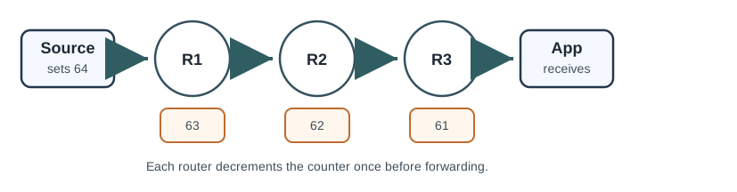
Before accepting the overview: ttl and hop limit bound how far a packet can travel claim, examine Figure 3.1 to connect the protocol description to observable control-plane, route-state, and packet evidence. This matters because a routing label or formed topology alone cannot prove that the required traffic path works or recovers at its boundaries.

TTL or Hop Limit decrementing from a source through routers R1, R2, and R3 before reaching the destination.
Figure 3.1: Each routed hop consumes one count. The remaining value is evidence about forwarding lifetime, not proof of path quality.

In Figure 3.1, the visual shows tTL or Hop Limit decrementing from a source through routers R1, R2, and R3 before reaching the destination. Start with the input or initial condition, follow the labelled relationships through each intermediate stage, and finish at the decision, output, or feedback path; at every transition, identify what evidence would confirm the change. This ordered reading connects the overview: ttl and hop limit bound how far a packet can travel discussion to the chapter’s running argument: a routing decision is credible only when its control state, forwarding result, failure response, and retest trigger can be checked together.

IPv4 TTL

An 8-bit field in the IPv4 header. Routers decrement it before forwarding and discard the packet when it reaches zero.

IPv6 Hop Limit

The IPv6 name for the same forwarding-lifetime idea. The name is clearer because it is about router hops, not elapsed time.

Loop Bound

A packet caught in a forwarding cycle eventually expires instead of consuming bandwidth, queues, and radio airtime forever.

Question
Answer
Why It Matters
Review Pitfall
Does TTL choose the route?
No. Routing tables, parent choices, and routing protocols select the next hop.
TTL only bounds how long the packet can keep being forwarded.
Treating a high TTL as proof that the selected path is correct.
Can TTL stop all loops?
It stops a looping packet eventually, but it does not fix the route state that caused the loop.
Control-plane loop prevention and packet-level loop bounding are separate protections.
Assuming RPL or another protocol makes packet hop limits irrelevant.
Does traceroute prove the whole path?
It shows routers that answered probes with increasing hop limits.
It is useful evidence, but replies can be filtered, rate-limited, asymmetric, or load-balanced.
Treating silent hops as proof that no router exists.

3.3 Practitioner: Choose Hop Budgets from Measured Paths and Repair Detours

IoT paths often include more routed hops than the device team first expects. A constrained mesh may forward through parents, a border router, site routing, VPN or private WAN routing, and cloud edge routing. A safe hop budget allows the expected path and realistic repair detours, while still limiting loop damage if routing state breaks.
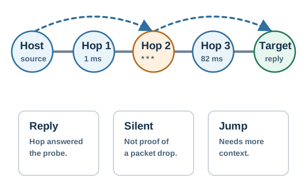
Before accepting the practitioner: choose hop budgets from measured paths and repair detours claim, examine Figure 3.2 to connect the protocol description to observable control-plane, route-state, and packet evidence. This matters because a routing label or formed topology alone cannot prove that the required traffic path works or recovers at its boundaries.

In Figure 3.2, the visual shows traceroute evidence showing increasing hop limits and Time Exceeded replies from routers along a path. Start with the input or initial condition, follow the labelled relationships through each intermediate stage, and finish at the decision, output, or feedback path; at every transition, identify what evidence would confirm the change. This ordered reading connects the practitioner: choose hop budgets from measured paths and repair detours discussion to the chapter’s running argument: a routing decision is credible only when its control state, forwarding result, failure response, and retest trigger can be checked together.

Traceroute runs from a source through a 1 ms reply, a silent hop and an 82 ms reply to the target. Silence is not proof of a drop; a latency jump needs context.
Figure 3.2: Traceroute evidence is strongest when paired with route state, return-path checks, and failure observations.

Inspect “Host” and “source” as separate claims in Figure 3.2. The role of “Hop 1” is to connect them, making visible how traceroute evidence is strongest when paired with route state, return-path checks, and failure observations. That distinction matters for Practitioner: Choose Hop Budgets from Measured Paths and Repair Detours.

3.3.1 Path Budget Example

A sensor sends through one mesh parent, one mesh router, a border router, a site router, and eight upstream routers. The normal path uses 12 routed hops. Hop Limit 16 allows the normal path but leaves only four hops for repair detours. Hop Limit 8 fails even when the network is healthy. Hop Limit 64 gives wide margin but lets a loop consume more forwarding attempts before expiry.

Evidence
What to Check
Design Implication
Common Mistake
Normal path
Count routed hops from sensor or gateway to the service and back.
The starting TTL or Hop Limit must be above the normal forward and return paths.
Testing only the uplink telemetry path and ignoring command return traffic.
Repair detour
Measure or model extra hops during parent repair, failover, VPN reroute, or site outage mode.
Leave enough margin for expected detours without masking loops for too long.
Choosing a value that passes the happy path but fails during repair.
Expiry signal
Capture ICMP or ICMPv6 Time Exceeded when policy allows it.
Expiry messages can reveal loops, unexpectedly long paths, or too-low hop limits.
Assuming no reply means no router or no loop.
Route state
Record route table entries, RPL parent and Rank state, or DODAG state near the failure.
Packet expiry evidence must be tied back to the control-plane reason.
Troubleshooting packet symptoms without checking route state.

Practical rule: pick a hop budget from observed path length plus realistic repair margin. Do not copy a default into firmware without proving the deepest valid path.

3.4 Under the Hood: Expiry Evidence Connects Packet Symptoms to Route State

When a router receives an IP packet, it checks forwarding state and the packet lifetime field. For IPv4 TTL and IPv6 Hop Limit, the router decrements the value as part of forwarding. If the result is zero, the router discards the packet and may send an ICMP or ICMPv6 Time Exceeded message to the source, subject to policy and rate limits.

Routing protocols try to keep packets out of loops. Distance-vector protocols use loop-avoidance techniques, link-state protocols converge on consistent topology views, and RPL uses DODAG orientation and Rank rules. TTL or Hop Limit is the packet-level fallback when those controls are wrong, stale, or temporarily inconsistent.
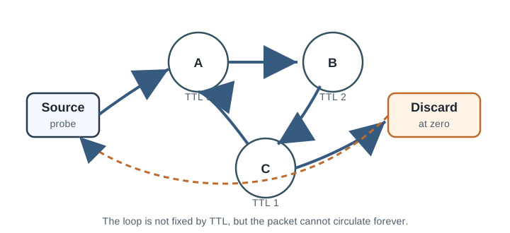
Before accepting the under the hood: expiry evidence connects packet symptoms to route state claim, examine Figure 3.3 to connect the protocol description to observable control-plane, route-state, and packet evidence. This matters because a routing label or formed topology alone cannot prove that the required traffic path works or recovers at its boundaries.

Routers A, B, and C forward a looping packet until the hop counter reaches zero and the packet is discarded.
Figure 3.3: TTL and Hop Limit limit a loop’s lifetime; they do not explain why the loop formed.

In Figure 3.3, the visual shows routers A, B, and C forward a looping packet until the hop counter reaches zero and the packet is discarded. Start with the input or initial condition, follow the labelled relationships through each intermediate stage, and finish at the decision, output, or feedback path; at every transition, identify what evidence would confirm the change. This ordered reading connects the under the hood: expiry evidence connects packet symptoms to route state discussion to the chapter’s running argument: a routing decision is credible only when its control state, forwarding result, failure response, and retest trigger can be checked together.

Signal
What It Can Mean
What It Cannot Prove Alone
Next Evidence
Time Exceeded
A packet expired before the destination, possibly due to a loop, long path, or low starting value.
It does not by itself identify the bad route entry or parent choice.
Collect route table, parent, DODAG, and recent-change evidence.
Silent traceroute hop
A router may be filtering, rate-limiting, using a different return path, or not sending errors.
It does not prove the hop is absent.
Cross-check with route state, packet capture, and adjacent hops.
Low received TTL
The packet may have crossed many routers or started with a low value.
It does not prove the hop count unless the initial value is known.
Record sender stack settings or observe controlled probes.
Repeated expiry
There may be a persistent loop or a firmware hop budget too small for the real path.
It does not say whether the control plane or firmware setting is at fault.
Compare route state, normal path, detour path, and hop-limit policy.

3.4.1 Review Boundary

Forward Path

Verify the routed hops from source to destination and the remaining hop value at the service boundary.

Return Path

Commands, acknowledgements, and Time Exceeded messages have their own routes and their own fresh counters.

Control Plane

Check routing tables, RPL parent state, Rank movement, and route-change timing near expiry events.

Retest Trigger

Retest when mesh depth grows, site routing changes, VPN paths change, or loop/expiry logs increase.

Failure mode: treating TTL as an availability fix. It is a damage limiter and diagnostic input; correct route state, parent choice, and return-path behavior still need separate proof.

3.5 Routing Tables and Route Types

3.5.1 Start With the Table Row

Check the Row That Carries the Alarm

Picture a sensor alarm that reaches a border router but never reaches the service beyond it. A gateway means the device or service that joins one network or system to another.

Name the destination, prefix, next hop, route source, metric, outgoing link, and expiry rule. Test the normal route, a missing next hop, two competing rows, and a stale row.

Keep the table before and after, packet direction, chosen row, time, and result. This proves one forwarding decision, not the full network; the deeper sections explain matching, preference, installation, expiry, and diagnosis.

A routing table row is a promise about one kind of traffic. It says which destination or prefix is in scope, which next hop should receive the packet, where the route came from, and which metric or priority makes it preferable.

Read the table row as an operating record, not as decoration. In an IoT path, the row may sit on a sensor parent, border router, gateway, or cloud edge, so the useful question is always whether that row supports the traffic direction the deployment actually needs.

3.5.2 Overview: Routing Tables Are Forwarding Decisions

A routing table is the lookup information a router uses when it receives a packet. The table does not describe every possible path through the network. It records the local device's best forwarding decision for destination prefixes it knows about.

Each useful route entry answers a small contract: which destination prefix matches, where should the packet go next, which interface sends it, where did the route come from, and how preferred is it compared with alternatives that are otherwise comparable.

That contract is especially important at IoT boundaries. A sensor, mesh parent, border router, site router, and cloud edge may each hold a different part of the route story. The table entry should be read with the device role and traffic direction in mind.

That role check prevents overclaiming. A sensor default route may be enough for telemetry, while the border router still needs prefix, firewall, and return-path evidence before a cloud service can command the sensor.

The claim in Overview: Routing Tables Are Forwarding Decisions needs more than a named protocol feature. Use Figure 3.4 to inspect how a route entry is a reviewable forwarding claim. Read the prefix first, then the next hop and interface, then the source and metric context; those visible roles identify the evidence this section must carry forward.

Routing table entry broken into its three essential components: destination network such as 192.168.1.0/24, next hop such as 10.0.0.1, and outbound interface such as eth0, with an example table row and a note that the router forwards using the longest-prefix match.
Figure 3.4: A route entry is a reviewable forwarding claim. Read the prefix first, then the next hop and interface, then the source and metric context.

In Figure 3.4, begin with “Routing Table Entry” and compare its role with “Three Essential Components.” The label “DESTINATION NETWORK” then marks the consequence to record. Together they show that a route entry is a reviewable forwarding claim. Read the prefix first, then the next hop and interface, then the source and metric context, linking the visual directly to Overview: Routing Tables Are Forwarding Decisions.

Destination Prefix

The address range the entry can match, such as a subnet, a sensor VLAN, or the default route.

Next Hop

The neighbor router or directly connected link used for the next forwarding step.

Route Source

The origin of the entry: connected, static, default, or learned by a routing protocol.

Metric

A comparison value used after the route is already comparable by prefix and source.

3.5.2.1 Default routes are fallbacks

An IPv4 default route, 0.0.0.0/0, or an IPv6 default route, ::/0, catches destinations that have no more specific match. It is not the best route by magic. It is the least-specific route that still gives the router somewhere to send otherwise unknown destinations.

3.5.3 Practitioner: Design Route State Around Boundaries

IoT routing-table design starts by naming the boundary. A constrained sensor, a mesh router, a border router, a site router, and a cloud or provider edge do not need the same route state. Put detailed route knowledge where it can be maintained and tested.

A small sensor can often use a default route toward a parent or gateway. A border router needs enough state to move traffic between the constrained network and the site or upstream network. A site router may summarize device networks, but the summary must not hide special inspection paths, migrations, or more-specific exceptions.

Keep route ownership in the record. Static routes need a maintainer and a cleanup trigger; learned routes need neighbor and policy evidence; default routes need a return-path check so they do not hide an unreachable sensor prefix.

For each exception, name who will remove or retest it after a gateway move, subnet migration, or routing-mode change.

To make Practitioner: Design Route State Around Boundaries reviewable, pause at Figure 3.5. It lays out how longest-prefix match is usually the first practical surprise: a more-specific route can win even when a broader route looks simpler, so the next decision can be tied to an observable state or transition.

Longest-prefix match example where destination 192.168.1.100 matches default, site, subnet, and sensor VLAN routes, with the sensor VLAN route selected.
Figure 3.5: Longest-prefix match is usually the first practical surprise: a more-specific route can win even when a broader route looks simpler.

Figure 3.5 first names “Destination”; set that evidence against “192.168.1.100,” then check what “0.0.0.0/0” adds. This sequence demonstrates how longest-prefix match is usually the first practical surprise: a more-specific route can win even when a broader route looks simpler and supplies the concrete basis for Practitioner: Design Route State Around Boundaries.

Route type
Forwarding question
Review evidence
Connected
Which directly attached network can this interface reach?
Interface address, link state, prefix length, and packet test on the local link.
Static
Which stable path has an operator deliberately configured?
Configuration record, next-hop reachability, migration owner, and stale-route removal trigger.
Dynamic
Which protocol learned this route, and what policy accepted it?
Protocol neighbor state, advertised prefix, route source, metric, and failover behavior.
Default
Where should unmatched destinations go?
Gateway reachability, return path, security boundary, and evidence that no more-specific route should apply.

3.5.3.1 IoT routing-table record

For a reviewable design, record the traffic direction, destination prefix, selected route, next hop, route source, preference model, metric meaning, return path, and retest trigger. This keeps telemetry uplink, command downlink, firmware downloads, and management access from being treated as one generic path.

3.5.4 Under the Hood: Lookup Order Before Metrics

Routing mistakes often come from comparing the wrong fields first. A router does not normally pick the lowest metric across every route in the table. It first finds matching prefixes, prefers the most specific match, resolves route-source preference for comparable entries, and then applies the metric rules for routes that are still competing.

This lookup order explains many surprising gateway behaviors. A broad default path can be healthy while a more-specific stale static route steals traffic, or a correct RPL parent can still fail a downlink claim because the root lacks current route state.

The reviewer should therefore replay the lookup with the real destination address before judging the metric. That single step often separates a routing-table defect from a firewall, DNS, or application symptom.

1. Match prefixes Find entries whose destination prefix includes the packet destination.
2. Choose specificity Prefer the longest matching prefix, such as a sensor VLAN route over a broader site summary.
3. Resolve source Use the platform's configured route-source preference when comparable routes exist.
4. Compare metrics Use the metric meaning for that protocol or route source only after the earlier decisions are settled.
5. Forward and prove Send to the next hop, decrement TTL or Hop Limit, and verify packet behavior in the needed direction.

3.5.4.1 RPL route evidence is separate

RPL parent choice, Rank, Objective Function state, and DAO route state are not interchangeable with a generic IP routing-table screenshot. For upward traffic, record the selected parent and metric reason. For downward traffic, record whether Storing or Non-Storing mode is in use and what route evidence proves reachability from the root toward the node.

Equal-cost paths, policy routes, firewall state, and NAT state can add more checks, but they do not remove the basic rule: the lookup result must be tied to the exact traffic direction under review. A telemetry success path does not automatically prove downlink command reachability.

3.5.5 Summary

Routing tables are local forwarding evidence. A route entry maps a destination prefix to a next hop or interface, records where the route came from, and gives comparison information for routes that are truly comparable. Longest-prefix match is the key lookup rule to check before arguing about metrics.

For IoT systems, route-table review should follow the boundary: sensor, parent, border router, site network, and upstream service. Keep constrained nodes simple, put detailed route state at maintainable boundaries, and prove both telemetry and command directions when the application depends on them.

3.5.6 Key Takeaway

A routing-table screenshot is not enough by itself. Turn it into a review record: exact destination prefix, selected next hop, route source, preference model, metric meaning, return path, failure behavior, and the retest trigger that keeps stale routes from surviving migrations.

3.5.7 See Also

3.6 Packet Switching and Failover

3.6.1 Start With One Forwarding Step

3.6.1.1 Follow One Packet, Then Break the Path

A clinic sensor sends a reading through several devices. Each device makes a local choice about the next step. No single step can prove that the reading reached the final service or remained useful when it arrived.

Give the packet an identity, source time, destination, age limit, and expected result. Record each next hop and the rule that selected it. Then remove one useful path, delay an update, fill a queue, and restore the link. Check loss, duplicates, order, repair time, and the state shown to the operator.

Keep urgent safe action near the equipment. A remote route may recover too late for a physical stop. When the path changes, keep the reading’s time, unit, quality, and version with it so the receiver can judge old evidence.

This trace proves only the tested route and failure. The deeper sections explain forwarding state, route updates, loops, metrics, and the difference between a reachable destination and a trustworthy application result.

Packet switching is the repeated act of making one local forwarding decision. A device receives a packet, checks the header, chooses an outgoing interface or neighbor, updates the loop limit, and sends the packet on without carrying the whole application in memory.

That local step is powerful because many small steps create an end-to-end path. It is also fragile in constrained networks, where one weak link, stale metric, or missing failover route can make a clean design behave poorly under real traffic.

3.6.2 Overview: Packet Switching Uses Current Forwarding State

Packet switching is the forwarding model used by IP networks. A message is carried in packets, each packet has addressing information in its header, and each router forwards the packet one hop at a time using the forwarding state it currently has.

This is different from reserving one fixed circuit before data flows. Packet-switched paths can share links with other traffic and can change after routing state changes. The tradeoff is that failover is not automatically instant or lossless.

For release review, that tradeoff must be visible to the application owner. A route change can be acceptable for periodic sensing but unacceptable for a command, alarm, or control loop that cannot tolerate duplicate or late packets.

The reason to inspect Figure 3.6 here is to verify Overview: Packet Switching Uses Current Forwarding State against a concrete model. It shows how packet Switching in a Data Network and identifies the observations that should survive into the review record.

Packet Switching in a Data Network: Server, Packet Switching Network, Multiple paths for independent packet routing, Path 1 Packets, Path 2 Packets, Router, • No fixed path established, • Packets reassembled at destination by sequence
Figure 3.6: Packet Switching in a Data Network

The evidence order in Figure 3.6 is “Packet Switching in a Data Network,” then “Server,” with “Packet Switching Network” as the deciding marker. This arrangement shows how packet Switching in a Data Network and reconnects the asset to Overview: Packet Switching Uses Current Forwarding State.

The key distinction

Packet switching gives each forwarding device a local next-hop decision. It does not guarantee that every packet in a flow takes the same path, that backup paths are already installed, or that applications will never see loss during a route change.

Packet

The network-layer unit that carries a destination address, source address, and payload through routed networks.

Forwarding State

The current table entry, next hop, interface, and metric decision a router uses for a packet.

Convergence

The interval between a topology change and the relevant devices installing updated forwarding decisions.

Recovery Boundary

The layer that detects loss and retries, such as transport behavior, CoAP reliability, a message queue, or application logic.

For IoT systems, the most important review question is practical: when a gateway, mesh parent, border router, or upstream link changes, what will the application observe? A packet-switched network can recover by forwarding later packets over another path, but the application still needs evidence for loss, delay, duplicate handling, stale values, and downlink commands.

3.6.3 Practitioner: Build the Failover Evidence Record

A useful packet-switching review records what happens before, during, and after a forwarding change. Do not stop at drawing a backup path. Prove which traffic depends on it, what detects the failure, how long the path is uncertain, and how the application handles packets affected by the change.

Practitioner: Build the Failover Evidence Record asks the reader to separate several claims that can look alike. Figure 3.7 shows how failover evidence connects route change behavior to the application result, not just to a topology diagram, so those claims can be checked independently.

Failover evidence workflow showing baseline path, controlled failure, convergence observation, application recovery, and retest trigger.
Figure 3.7: Failover evidence connects route change behavior to the application result, not just to a topology diagram.

At Figure 3.7, use “Failover evidence workflow showing baseline path” to state the initial claim and “controlled failure” to locate its dependency. “convergence observation” shows where confirmation is expected. Read together, they show how failover evidence connects route change behavior to the application result, not just to a topology diagram for Practitioner: Build the Failover Evidence Record.

1. Baseline Record the normal route, next hop, return path, and packet observation for the traffic that matters.
2. Trigger Name what detects the fault: link loss, neighbor state, routing update, gateway health, or application timeout.
3. Convergence Observe when forwarding entries change and what happens to packets during that interval.
4. Recovery Check retransmission, duplicate handling, stale-data marking, command acknowledgement, and operator visibility.
5. Retest Define when to repeat the test after topology, firmware, metric, gateway, or policy changes.

3.6.3.1 Evidence Ledger

Record Field
Evidence Question
Review Action
Traffic scope
Which telemetry, command, firmware, or management path is being tested?
Name source, destination, protocol, direction, freshness need, and consequence of loss.
Forwarding state
Which route, next hop, metric, parent, or gateway is selected before and after failure?
Keep route snapshots, parent or neighbor state, packet traces, and the selected alternate path.
Packet impact
Were packets dropped, delayed, duplicated, reordered, or accepted late?
Use timestamped test traffic and match the result to application retry and stale-data behavior.
Return path
Does the reply or command direction survive the same change?
Test both directions and inspect stateful firewall, NAT, broker, or gateway logs where relevant.
Release gate
What change invalidates the evidence?
Retest after route metrics, parent choice, gateway failover policy, firmware timing, or security policy changes.

Metric choice changes the preferred path

A shortest-hop path is not always the strongest IoT path. A route with more hops may be more stable when the links are cleaner, while a path with lower administrative cost may be preferred in a managed site network. Record what the metric means before using it as evidence.

3.6.4 Under the Hood: Metrics and Convergence Are Local Contracts

Under the hood, each forwarding device makes a local decision. It receives a frame, extracts the packet, checks the destination, applies its forwarding rules, decrements TTL or IPv6 Hop Limit, rewrites the link-layer wrapper for the next link, and transmits. The application payload may be unchanged, but the forwarding evidence changes at every hop.

The claim in Under the Hood: Metrics and Convergence Are Local Contracts needs more than a named protocol feature. Use Figure 3.8 to inspect how three Routing Metrics; those visible roles identify the evidence this section must carry forward.

Three Routing Metrics: Same network, different metrics produce different optimal paths, Hop Count, Best: S → B → D, 2 hops (shortest path), ETX (Link Quality), 1.1, 5.0, 1.2, 1.0
Figure 3.8: Three Routing Metrics

In Figure 3.8, begin with “Three Routing Metrics” and compare its role with “Same network.” The label “different metrics produce different optimal paths” then marks the consequence to record. Together they show that three Routing Metrics, linking the visual directly to Under the Hood: Metrics and Convergence Are Local Contracts.

3.6.4.1 Metric and Failure Boundaries

Boundary
What It Means
Review Risk
Hop count
Counts routers crossed and prefers fewer hops when all other assumptions are comparable.
Can prefer a short lossy wireless path over a longer but more reliable path.
Configured cost
Uses operator-assigned or protocol-derived interface costs to steer traffic in a managed network.
Can be stale if link capacity, policy, or reference assumptions changed without updating the route plan.
ETX-style link quality
Estimates expected transmissions, making lossy links visible to an IoT routing objective.
Can be misleading if measurements are stale, asymmetric, or not representative of command traffic.
Convergence interval
Represents the time when devices detect change, compute or advertise updates, and install new forwarding state.
Can expose packet loss, duplicate delivery, stale dashboard values, or unacknowledged commands.
Asymmetric path
Forward and return traffic may use different devices, policies, or stateful boundaries.
Can break commands or acknowledgements when firewalls, NAT, brokers, or gateways expect both directions.

ETX is useful because it makes link quality part of the routing discussion, but it is still a model. A lower ETX path is a better estimate under the measurement assumptions, not proof that every future packet is safe. RPL objective functions, site routing protocols, and gateway policies each need their own evidence because they optimize different contracts.

Under-the-hood review rule

When a path changes, separate route selection from application recovery. Route selection explains where later packets go. Recovery explains how missing, late, duplicate, or reordered data is handled by the protocol stack and the application workflow.

3.6.5 Summary

Packet switching forwards packets hop by hop using current forwarding state. It lets networks share links and adapt after route changes, but it does not make failover instantaneous or lossless. Packets sent during failure detection or convergence can be dropped, delayed, duplicated, or reordered, so application recovery remains part of the design.

For IoT systems, the practical evidence includes the normal path, alternate path, route or parent change, metric meaning, convergence behavior, return path, and the protocol or application layer that handles recovery. A shortest path, lowest cost, or cleaner ETX estimate is useful only when the team can explain what that metric means and when the evidence must be retested.

3.6.6 Key Takeaway

Treat packet switching as a forwarding contract, not a failover guarantee. Prove the selected path, the convergence interval, the return direction, and the recovery behavior for the IoT traffic that matters.

3.6.7 See Also

3.7 Summary

  • IPv4 TTL and IPv6 Hop Limit are router-hop counters, not real-time timers.
  • Routers decrement the counter during forwarding and discard packets that reach zero.
  • TTL and Hop Limit bound loop damage but do not select routes or repair route state.
  • Traceroute uses increasing hop limits to collect Time Exceeded responses from routers.
  • IoT hop budgets should be based on measured path length, repair detours, return paths, and loop-damage limits.
  • Expiry evidence must be tied to routing tables, RPL state, parent choices, and recent changes.

3.8 Key Takeaway

TTL and Hop Limit are safety and diagnostic controls. Use them to bound packet lifetime and expose path evidence, but prove routing correctness separately with route state, parent behavior, and return-path tests.

3.9 See Also