16 Choosing IoT Communication Tech
16.1 Start With the Message Journey
Communication technology choices make sense when you follow one message from source to destination. A telemetry sample, alarm, command, firmware update, or discovery packet has a distance, timing need, power cost, reliability target, and security context.
Start with that journey before naming a protocol. The right communication enabler is the one whose range, bandwidth, latency, energy, addressing, and operations evidence match the job the architecture needs the message to do.

Phoebe’s Why
Antenna gain is not amplification – it is focus, squeezing a fixed radiated power into a narrower solid angle instead of spreading it over the whole sphere. That single fact explains why this chapter’s own “Field Or Campus Area” tier and “Wide Area” tier ask for opposite antenna choices even though both are radios. A field of distributed room sensors needs to be heard from every direction around a gateway, so a wide, low-gain pattern is the right shape even though it buys less range per watt. A vehicle gateway’s cellular or satellite backhaul only ever needs to reach one fixed direction – the tower or the sky – so a narrow, high-gain pattern is the right shape, and the range it buys back is not a bonus, it is the point. The same word, “gain,” means a trade in opposite directions depending on whether the antenna’s job is coverage or reach.
The Derivation
An isotropic source spreads power evenly over the full sphere (\(4\pi\) steradians). A directional antenna of gain \(G\) concentrates the same power into a smaller solid angle, idealized as one main lobe:
\[\Omega \approx \frac{4\pi}{G}, \qquad \text{fraction of sphere covered} = \frac{\Omega}{4\pi} = \frac{1}{G}\]
Regulators cap the combination of conducted power and antenna gain as EIRP:
\[\mathrm{EIRP(dBm)} = P_t(\mathrm{dBm}) + G(\mathrm{dBi})\]
At a fixed EIRP ceiling, extra gain buys extra range in the covered direction because received power density scales with \(G/d^2\), so for constant received power \(d \propto \sqrt{G}\).
Worked Numbers: This Chapter’s Room-Sensor Vs. Vehicle-Gateway Pair
- Room sensor (Field Or Campus Area): a near-omni antenna, catalog-typical \(G=3\) dBi (\(=1.995\times\)), covers \(\Omega=4\pi/1.995=6.30\) sr, or \(50.1\%\) of the full sphere – close to every direction, which is exactly what a scattered set of room sensors reporting to one gateway needs.
- Vehicle gateway (Wide Area backhaul): catalog-typical directional antenna at \(G=9\) dBi (\(=7.94\times\)), covers \(\Omega=4\pi/7.94=1.58\) sr, or \(12.6\%\) of the sphere – a narrow wedge, acceptable only because the target (a cell tower or satellite) sits in a known, fixed direction.
- Range payoff for that trade: at the same EIRP ceiling, the 9 dBi link reaches \(\sqrt{7.94/1.995}=2.00\times\) the range of the 3 dBi link – but only inside its \(12.6\%\) wedge; outside it, the 9 dBi antenna hears almost nothing.
- Why the mismatch matters: fitting the vehicle gateway’s narrow antenna to the room-sensor job would leave most sensors outside the beam entirely; fitting the room sensor’s wide antenna to the vehicle-gateway job would halve the backhaul range for no coverage benefit, since there is only ever one direction to reach. This is the physical reason this chapter’s own room-sensor and vehicle-gateway proof lists both say “antenna placement” but mean geometrically opposite requirements.
16.2 Learning Objectives
By the end of this chapter, you will be able to:
- Classify communication technology by network scale, payload behavior, topology, and lifecycle records.
- Explain the difference between coverage, capacity, and reliability in an IoT communication design.
- Match common technology families to IoT situations without relying on brittle range or price shortcuts.
- Identify the field proof needed before approving a communication technology for a deployment.
- Build a communication decision record that supports installation, debugging, updates, and service handoff.
16.3 Communication as Architecture
Communication technology connects physical events to software decisions. It determines whether telemetry reaches a gateway, whether commands arrive on time, whether a device can sleep, whether diagnostics are available, and whether the system still works after installation conditions change.
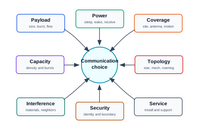
Start with these fit questions:
- Payload: How large is each message, how often is it sent, and does traffic arrive as steady reports or bursts?
- Latency: Which messages are time-sensitive, and which can tolerate delay or scheduled upload?
- Power: Is the device mains powered, rechargeable, energy harvested, or expected to run unattended for long periods?
- Coverage: Where must the link work: body area, room, building, campus, field, vehicle route, or remote site?
- Capacity: How many devices may talk at once during normal operation, alarms, recovery, or maintenance?
- Topology: Is the design point-to-point, star, mesh, gateway based, roaming, or a hybrid?
- Environment: What materials, enclosures, antennas, mounting positions, and nearby transmitters affect the link?
- Security: Where does identity, encryption, key rotation, and access control change hands?
- Service: How will installers verify the link and how will support staff diagnose later failures?
Selection rule: A communication technology is not approved by category name. It is approved when the project can show payload, power, coverage, capacity, coexistence, security, and service proof for the intended site.
16.4 Network Scale Starts Decisions
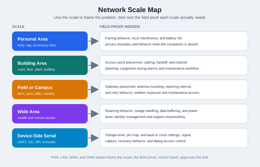
Network labels such as PAN, LAN, MAN, and WAN are useful vocabulary, but they are too broad to make the decision alone. Use them to frame the scale of the problem, then test the actual link behavior and operational responsibilities.
16.4.1 Personal Area
Short-range device-to-phone, device-to-tag, or device-to-accessory links. Typical proof includes pairing behavior, local interference, battery behavior, privacy boundary, and what happens when the companion device is absent.
16.4.2 Building Area
Room, floor, plant, or building connectivity. Typical proof includes access-point placement, cabling options, handoff behavior, channel planning, congestion during alarms, and local maintenance workflow.
16.4.3 Field Or Campus Area
Distributed sensors across farms, yards, campuses, utility sites, or industrial outdoor spaces. Typical proof includes gateway placement, antenna mounting, reporting interval, retry behavior, weather exposure, and maintenance access.
16.4.4 Wide Area
Mobile assets, remote assets, or sites outside local infrastructure. Typical proof includes roaming behavior, outage handling, data buffering, power draw, identity management, and support responsibility.
16.4.5 Device-Side Serial
Board-level and module-level links such as UART, I2C, SPI, and service consoles. Typical proof includes voltage level, pin map, baud or clock settings, signal capture, recovery behavior, and debug access control.
16.5 Technology Families And Fit Signals
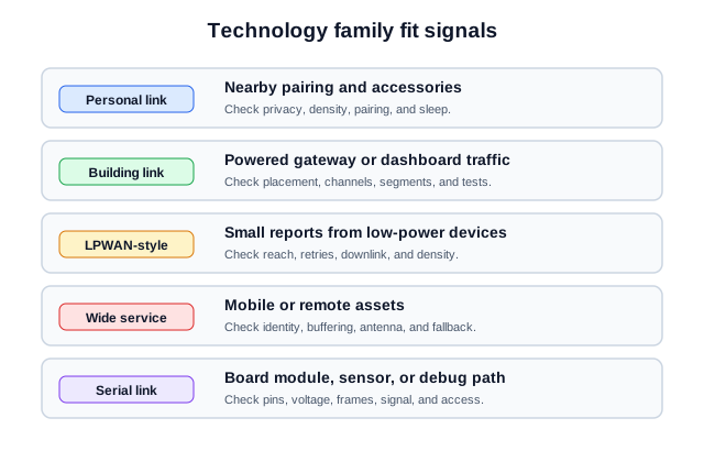
The same communication family can be a good or poor fit depending on payload, power, installation, and support context. Treat these as fit signals, not as permanent rankings.
16.5.1 Short-Range Personal Links
Examples include Bluetooth LE, NFC, and IEEE 802.15.4-based patterns. They fit local pairing, commissioning, tags, wearables, nearby controls, and low-power accessory links. Check pairing reliability, local density, sleep behavior, and what happens when the nearby coordinator is unavailable.
16.5.2 Building Networks
Examples include Ethernet and Wi-Fi patterns. They fit cameras, gateways, dashboards, controllers, and devices with local power or cabling. Check access placement, channel planning, switch capacity, power source, segmentation, and how maintenance staff will verify link health.
16.5.3 Low-Power Wide-Area Links
Examples include LPWAN-style patterns for small, infrequent messages from distributed devices. They fit sparse telemetry, alarms, metering, and remote monitoring when payload size and latency tolerance are modest. Check gateway coverage, device density, duty cycle, downlink needs, and retry policy.
16.5.4 Wide-Area Service Links
Examples include cellular IoT and satellite patterns. They fit mobile assets, moving vehicles, remote locations, and deployments that cannot rely on local infrastructure. Check identity, roaming, outage buffering, antenna placement, power budget, service monitoring, and fallback behavior.
16.5.5 Device-Side Serial Links
Examples include UART, I2C, SPI, and maintenance consoles. They fit board-to-module interfaces, debug logs, bootloaders, sensors, displays, and factory service access. Check electrical levels, frame settings, bus loading, signal integrity, connector access, and diagnostic exposure.
16.6 Coverage, Capacity, And Reliability
A link can cover the site and still fail the design. Coverage asks whether a signal reaches the device. Capacity asks whether the network can handle the number and timing of messages. Reliability asks whether messages arrive with enough consistency for the application and whether failures can be detected, retried, buffered, or escalated.
Use a three-part field check:
- Coverage proof: measured link quality at representative locations, orientations, enclosures, and mounting heights.
- Capacity proof: normal traffic, alarm bursts, startup storms, firmware maintenance, and gateway or access-point limits.
- Reliability proof: retry behavior, duplicate handling, message ordering, offline buffering, time synchronization, and alerting when the link degrades.
Do not approve a communication technology because a single test device connected once. A field check needs representative locations, realistic payloads, realistic traffic timing, and failure handling proof.
16.7 Topology And Ownership
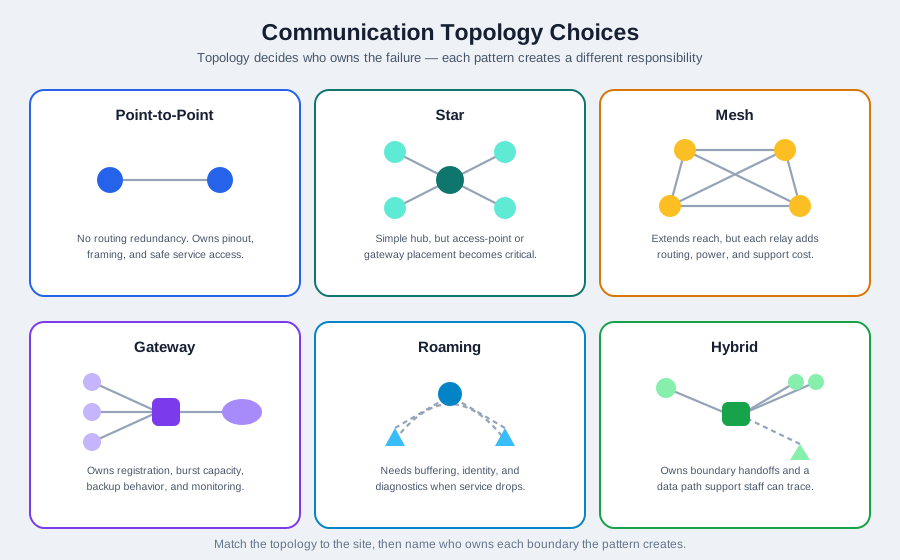
Topology determines who owns the failure. A point-to-point serial link may be easy to trace, but it gives no routing redundancy. A star network may simplify gateway management, but gateway placement becomes critical. A mesh can extend local reach, but each relay adds planning and support complexity. A roaming wide-area design can reduce local infrastructure, but it needs strong buffering and diagnostics when service is intermittent.
16.7.1 Point-To-Point
Use when two endpoints have a clear relationship, such as a module connected to a controller or a maintenance console connected to a device. Proof must include pinout, signal settings, framing, and safe service access.
16.7.2 Star Or Gateway
Use when many devices report through a common access point, gateway, or base station. Proof must include gateway placement, device registration, capacity during bursts, backup behavior, and operational monitoring.
16.7.3 Mesh
Use when local relays are needed and each node can support the extra routing responsibility. Proof must include route stability, relay power budget, self-healing behavior, firmware compatibility, and what happens when relay nodes move or fail.
16.7.4 Roaming Or Wide-Area
Use when assets move or sites cannot depend on local infrastructure. Proof must include buffering, identity, coverage variation, antenna placement, link-state reporting, and how delayed messages are handled.
16.7.5 Hybrid
Use when different parts of the same system need different communication patterns, such as wired cameras, low-power field sensors, and a wide-area gateway backhaul. Proof must include boundary ownership and a data path that support staff can trace.
16.8 Cold-Chain Link Choice
A cold-chain monitoring project needs temperature sensors in storage rooms, pallet tags at loading docks, vehicle gateways, and supervisor dashboards. A single communication technology would create weak points because the assets have different power, mobility, and payload patterns.
The decision separates the communication work:
- Room sensors: Low-rate telemetry, battery awareness, local obstruction checks, and alarm burst behavior.
- Loading dock tags: Short-range identification, high local density during loading, and fast association with the dock gateway.
- Vehicle gateway: Wide-area backhaul, offline buffering, identity management, antenna placement, and delivery-route coverage variation.
- Dashboard link: Building network reliability, segmentation, access control, and operational monitoring.
- Service path: Installer checklist, link-quality record, debug access, and escalation path when data stops arriving.
This is a hybrid architecture. The important proof is not a single protocol comparison table; it is a traceable record showing why each link exists, what it carries, where it can fail, and how the team will know.
16.9 Communication Decision Workflow
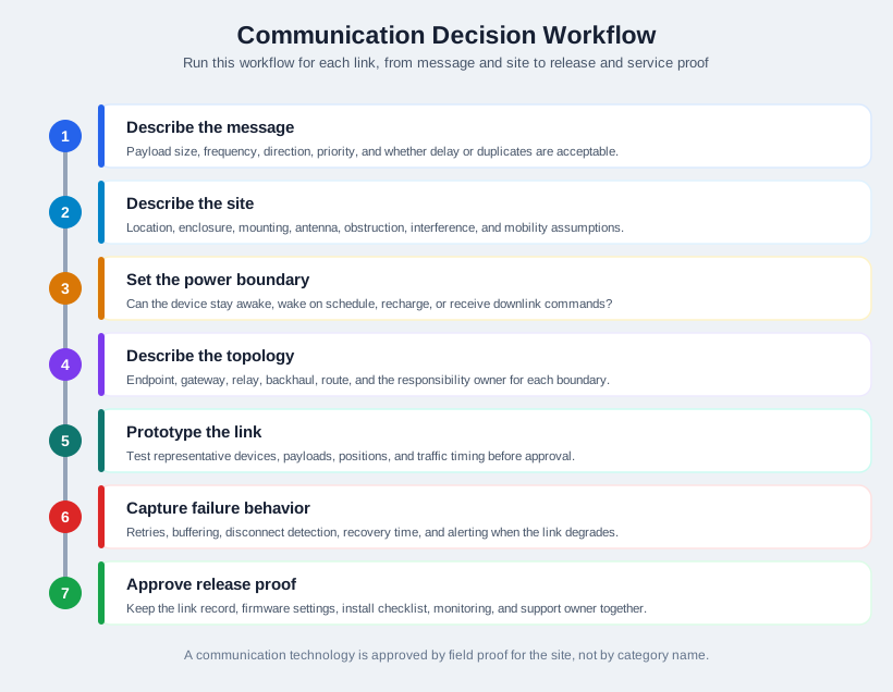
Follow this workflow for each communication link:
- Describe the message. Record payload size, frequency, direction, priority, and whether delayed or duplicated messages are acceptable.
- Describe the site. Record location, enclosure, mounting, antenna, obstruction, interference, and mobility assumptions.
- Describe the power boundary. Record whether the device can stay awake, wake on schedule, recharge, or receive downlink commands.
- Describe the topology. Record endpoint, gateway, relay, backhaul, route, and responsibility for each boundary.
- Prototype the link. Test representative devices, payloads, positions, and traffic timing.
- Capture failure behavior. Record retries, buffering, disconnect detection, recovery time, and alerting.
- Approve release proof. Keep the link record, firmware settings, installation checklist, monitoring signals, and support owner together.
16.10 Communication Decision Record
A durable communication decision should leave a compact record that another engineer can reuse during deployment and incident analysis.
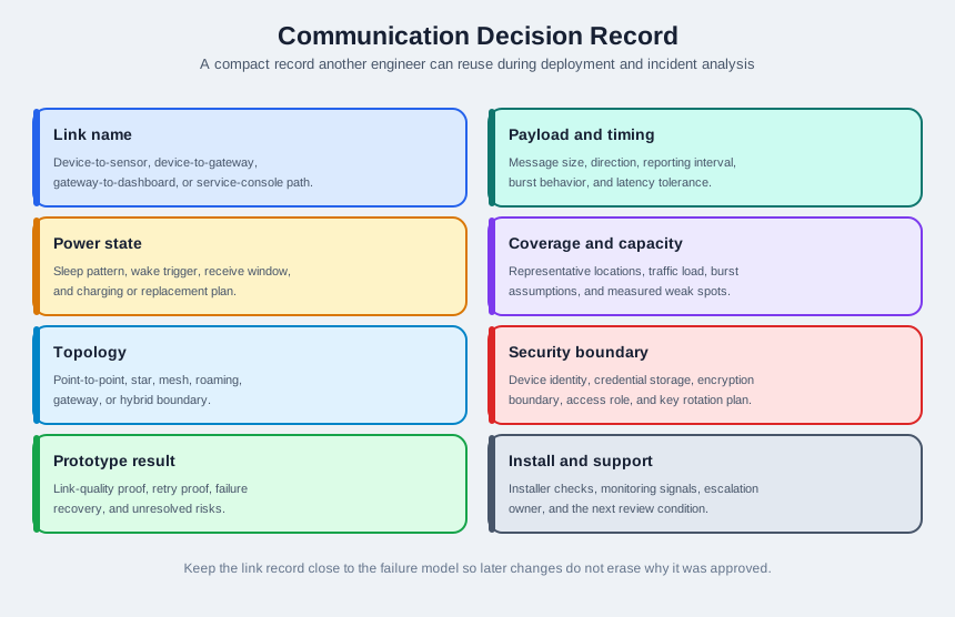
Record these fields:
- Link name: Device-to-sensor, device-to-gateway, gateway-to-dashboard, or service-console path.
- Payload and timing: Message size, direction, reporting interval, burst behavior, and latency tolerance.
- Power state: Sleep pattern, wake trigger, receive window, charging or replacement plan.
- Coverage and capacity: Representative locations, traffic load, burst assumptions, and measured weak spots.
- Topology: Point-to-point, star, mesh, roaming, gateway, or hybrid boundary.
- Security boundary: Device identity, credential storage, encryption boundary, access role, and key rotation plan.
- Prototype result: Link-quality proof, retry proof, failure recovery, and unresolved risks.
- Install and support: Installer checks, monitoring signals, escalation owner, and next review condition.
16.11 Interaction: Choose The Field Proof
16.12 Match Tech Family to Fit Signals
16.13 Order Communication Decisions
16.14 Common Pitfalls
Longer reach does not automatically mean better fit. A link also needs capacity, power behavior, diagnostics, security, and support evidence.
Normal traffic may be small, but alarms, reconnects, startup events, and maintenance jobs can create bursts. Capacity checks must include these cases.
Gateway placement, configuration, update policy, local storage, and monitoring are architectural responsibilities. Treating the gateway as invisible makes later troubleshooting harder.
A successful lab connection is useful, but it does not prove performance inside enclosures, behind walls, near machinery, in vehicles, or during service events.
UART and other service interfaces are helpful for diagnostics, but they can expose logs, bootloaders, or configuration paths. Check access control and service procedures before release.
16.15 Overview: Choose By Communication Job
If you only need the shortcut, this layer is enough: do not ask which radio is best in general. Ask what the link must carry, how often it must carry it, where it must work, and how the device is powered.
For a cold-chain system, the answer will not be one technology name. A room temperature sensor may send a small reading every few minutes and need low sleep current, local gateway coverage, and an alarm path when a freezer warms. A dock tag may need nearby identification during a loading burst, where Bluetooth LE, NFC, or IEEE 802.15.4-style local links could be considered only after density and pairing behavior are tested. A vehicle gateway may need LTE-M, NB-IoT, cellular data, satellite, or another backhaul with route coverage, buffering, and antenna placement evidence. A supervisor dashboard may simply need Ethernet or Wi-Fi with segmentation and monitoring.
The practical beginner move is to name the communication job before naming the technology. Write one row per link: device-to-sensor, device-to-gateway, gateway-to-cloud, dashboard-to-service, and service-console-to-device. For each row, record payload size, direction, timing, acceptable delay, power state, coverage area, site obstruction, expected device count, burst case, security boundary, and who will diagnose it after installation. A technology family is a candidate only after it fits that row.
When two rows look similar, keep them separate until the tests prove they share the same failure behavior. A freezer alarm, firmware update, and periodic reading can use the same gateway but still need different approval evidence.
Small sleepy telemetry
LPWAN-style links can fit sparse meter, farm, or environmental reports when payloads are small and downlink demand is modest.
Local high-rate traffic
Ethernet or Wi-Fi can fit gateways, dashboards, cameras, and powered equipment when capacity and local operations are available.
Mobile or remote assets
Cellular IoT, satellite, or a hybrid backhaul can fit moving vehicles and remote sites when roaming, identity, buffering, and antenna placement are planned.
16.16 Practitioner: Prove The Link In Context
A communication choice is ready when the team can point to representative tests, not only to a technology label. The cold-chain example needs different proof for a room sensor, dock tag, vehicle gateway, and dashboard link.
Make the link record measurable. For a radio link, capture location, antenna orientation, enclosure state, RSSI or signal-quality reading when the stack exposes it, packet delivery, retry count, duplicate handling, and time to recover after gateway restart. For a low-power device, add sleep current, wake interval, receive window, expected battery capacity, temperature effect, and the cost of an alarm burst. For Wi-Fi or Ethernet, add access-point or switch placement, VLAN or network segment, expected concurrent devices, firmware-update traffic, and what operators see when the link is degraded.
Run at least one test that resembles the worst real operating case. Put the temperature sensor in its actual enclosure, behind the expected door or wall, near compressors or pallet racks, and send the real payload on the planned interval. Exercise a loading-dock burst with many tags arriving together. Drive the gateway route or emulate the route with coverage records and offline buffering. Then hand the record to an installer or support engineer and check whether they can answer three questions: where the link should work, what failure looks like, and what action is safe.
If a record lacks units, thresholds, and sample conditions, it is not ready. A note such as "good signal" should become a measured location, device count, payload, firmware version, retry limit, and pass/fail rule.
Payload and timing
Record message size, direction, interval, burst behavior, priority, and acceptable delay for each link.
Site and antenna
Measure real mounting positions, enclosures, walls, vehicles, machinery, weather exposure, and nearby transmitters.
Operations path
Name the installer check, monitoring signal, debug access, update path, and support owner for later failures.
16.17 Why Good Links Fail Later
A communication link that works on the bench can fail after installation because the physical layer, traffic pattern, and support workflow have changed. The architecture decision must account for those moving parts.
Most late failures are cross-layer failures. A UART service console may look reliable until a voltage-level mismatch, baud-rate assumption, missing ground reference, or exposed bootloader turns it into a support and security issue. A Wi-Fi sensor may pass a desk test but fail when roaming, metal shelving, channel congestion, or power-save behavior changes. An LPWAN-style meter may pass sparse reporting but fail when downlinks, acknowledgements, or alarm bursts exceed the duty-cycle and battery assumptions. A cellular gateway may pass a parking-lot test but lose its route when antenna placement, carrier coverage, SIM identity, or offline queue limits change.
That is why the architecture record needs both engineering and operations evidence. The engineering side names the protocol settings, timing assumptions, retry limits, buffering behavior, and credential boundary. The operations side names the installer check, monitoring signal, alert threshold, reset path, firmware-update path, and owner who can act. When any of those facts changes, the communication technology has to be reviewed again rather than treated as an invisible transport detail.
A small version table helps: record the device firmware, gateway image, antenna part, SIM profile, broker topic, and installer checklist revision used for the approval test.
- Capacity collapse: alarm bursts, reconnect storms, or firmware maintenance can overload a gateway that handled normal telemetry.
- Power mismatch: a protocol that works while plugged into a laptop may drain a sealed battery device in the field.
- Placement drift: antenna orientation, enclosure material, pallet loading, or vehicle routing can change received signal quality.
- Service blind spot: support teams cannot fix a link they cannot observe, identify, reset, or update safely.
16.18 Summary
Communication technology selection is an architecture decision, not a shopping list. The right choice depends on payload behavior, latency tolerance, power budget, coverage, capacity, topology, environment, security boundary, and support workflow. PAN, LAN, field-area, wide-area, and serial categories help organize the discussion, but approval requires proof from representative tests and a record that installers and support teams can reuse.
16.19 Key Takeaway
Communication technology is an architectural enabler only when range, payload, latency, power, security, spectrum, and operations fit the deployment.
16.20 What’s Next
- IoT Evolution and Enablers Overview for the broader history and convergence of IoT enabling technologies.
- Technology Selection and Energy for energy-aware selection tradeoffs and battery-sensitive architecture checks.
- Labs and Assessment for practice applying communication, energy, and architecture field proof.