3 NB-IoT Technical Specifications
Spec Constraints, Deployment Modes, and Validation Evidence
Overview: A Specification Is a Constraint Stack
NB-IoT technical specifications tell you what the cellular standard permits. They do not prove that a specific module, firmware build, operator network, SIM profile, antenna, enclosure, payload, or power policy will expose the same behavior in the field. Treat every specification claim as a constraint that needs evidence before it becomes a product assumption.
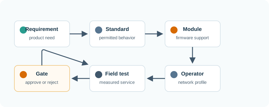
The practical reading habit is to separate four layers: the standard capability, the selected device support, the operator profile, and the measured field result. A design is ready only when those layers support the same service claim.
For each feature, ask four questions. Does the standard permit the behavior? Does the chosen module and firmware implement it in the required bands and modes? Does the target operator enable it for the selected SIM or eSIM profile? Does the installed product measure the expected payload, timer, coverage, and power behavior? A missing answer at any layer turns a specification item back into a risk.
This is especially important for release-era labels, peak rates, deployment modes, coverage enhancement, and power-saving features. Those terms are useful vocabulary, but they are not guarantees of commercial service. The overview record should translate each term into a product transaction that can be observed: attach, transfer, acknowledge, sleep, retry, recover, and report support evidence.
When the evidence differs from the specification expectation, prefer the measured service result. The product ships on the selected stack, not on the broadest table in the standard. Keep both the expected capability and the measured exception in the validation record so the next hardware, firmware, or operator change can be tested against the original reason for concern.
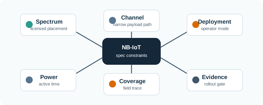
Permitted capability
The standard defines possible radio, access, power, and architecture behavior. It is the starting vocabulary, not the rollout proof.
Device support
The module limits bands, firmware features, command behavior, certification scope, and power-state behavior.
Network profile
The carrier controls deployment mode, enabled features, SIM or eSIM policy, roaming behavior, and support routes.
Measured service
The installed product proves attach behavior, payload receipt, retries, latency, current draw, recovery, and operations ownership.
Practitioner: Convert Spec Claims into a Validation Record
A useful validation record names the capability the product depends on, then shows how the final device and target operator support it. The record should include deployment mode, band support, coverage class, payload pattern, power-state policy, data path, SIM or eSIM profile, and support owner. Any item without evidence remains an assumption.
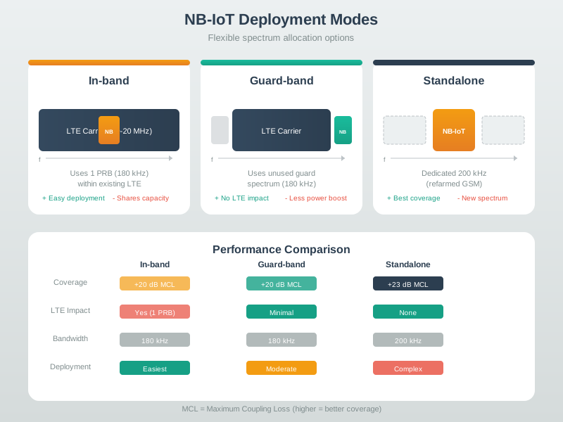
Deployment mode is a common example. Standalone, guard-band, and in-band placement are real NB-IoT concepts, but the product team does not choose them independently in the field. The operator service and regional spectrum plan decide what is available; the device team must verify service behavior with the selected module and installed product.
Under the Hood: The Product Transaction Is the Real Spec Test
The deepest mistake is reading a specification as if it were a finished service-level agreement. The real test is the product transaction: wake or attach, exchange a compact payload, wait for any needed response, log the server receipt, handle retries, and return to the intended power state. That transaction exposes the hidden coupling between radio coverage, scheduler behavior, half-duplex exchange, payload shape, timers, firmware, SIM profile, operator policy, and cloud handling.
This is why peak values and broad release labels are weak evidence. They may describe permitted behavior under favorable assumptions, but the design needs measured service in the target environment.
Use service timing
Plan from measured transaction duration and server receipt, not from a radio peak value.
Measure the whole cycle
Include attach, retries, response windows, current trace, recovery, and sleep return.
Record the owner
NB-IoT failures cross device, operator, SIM, firmware, cloud, and field-operation boundaries.
3.1 Start With the Story
A specification matters when it explains what the device can really ask the network to do. Bandwidth, repetition, CE level, and power class are not trivia; they decide whether a buried or indoor sensor can trade speed for reach.
Start simple: read each NB-IoT number as a deployment promise that must be checked against coverage, battery, payload, and operator support.

Phoebe’s Why
A compact NB-IoT module has no room for a directional antenna, and a buried or indoor device cannot be aimed at a tower anyway, so its practical antenna is close to isotropic – no free lunch from gain. Coverage enhancement (repetition, CE level) reaches those hard sites without asking the device antenna to do anything it physically cannot. The base-station side pays a different way: cellular sectors deliberately give up omnidirectional coverage, committing to a wedge of sky aimed at the ground, and buy back a large gain figure in exchange for that narrowed pattern. The same conserved-power geometry from the antenna-gain phenomena appears twice in one link, spent in opposite places.
The Derivation
EIRP combines conducted power and antenna gain:
\[\mathrm{EIRP(dBm)} = P_t(\mathrm{dBm}) + G(\mathrm{dBi})\]
An antenna’s directivity relates to the solid angle \(\Omega\) it concentrates power into:
\[G = \frac{4\pi}{\Omega}\]
Using the Kraus estimate in terms of the two half-power beamwidths \(\theta_E, \theta_H\) (degrees):
\[G \approx \frac{41253}{\theta_E\,\theta_H}\]
A near-isotropic device (\(\Omega \approx 4\pi\), full sphere) sits at \(G \approx 0\) dBi; a sectored base-station antenna narrows \(\Omega\) and raises \(G\) by the same factor it shrinks coverage angle.
Worked Numbers: Device Versus Sector
- UE side (3GPP Power Class 3, a real standardized value): \(P_t = 23\) dBm conducted, near-isotropic antenna \(G \approx 0\) dBi, so \(\mathrm{EIRP}_{UE} = 23\) dBm \(\approx 200\) mW (3 s.f.)
- Base-station side, typical macro sector antenna (illustrative horizontal beamwidth 65 degrees, vertical 7 degrees – common published figures, not a specific operator spec): \(G \approx 41253/(65\times7) = 41253/455 = 90.7\) (linear) \(= 10\log_{10}(90.7) = 19.6\) dBi
- That 19.6 dBi means the sector delivers about \(90.7\times\) the power density on axis that an isotropic antenna would, for the same conducted power – roughly the same order of magnitude as the repetition-count gains this chapter’s coverage-enhancement discussion depends on, but bought from antenna geometry instead of time-domain repetition
- The trade is explicit: the sector’s 65 degree by 7 degree wedge covers a tiny fraction of the full sphere (\(4\pi\) sr \(\approx 41253\ \text{deg}^2\)), so \(455/41253 = 1.10\%\) of all directions – everywhere outside that wedge gets none of the 19.6 dB benefit, which is exactly why a device’s measured service depends on which sector, not just which operator, serves it
The module data sheet and the operator profile this chapter asks for are two different antenna-gain stories: the device side stays near 0 dBi so it can be installed in any orientation, and the network side spends its gain on a fixed, engineered sector – so a coverage-enhancement claim is a statement about both budgets working together, not about either antenna alone.
3.2 Summary
NB-IoT technical specifications are the vocabulary and limits for design review, not deployment promises. A defensible design turns each specification claim into evidence across the standard, selected module, firmware, operator profile, SIM or eSIM behavior, installed radio path, payload transaction, power trace, application receipt, and support owner.
3.3 Key Takeaway
Treat every NB-IoT specification claim as a testable assumption. Approve the final product behavior only when module, operator, field, payload, power, and application evidence support the same service claim.
3.4 See Also
Builds the narrowband fit model for compact telemetry, operator service, and sleep-first devices.
Explains the radio access behavior behind attach, scheduling, retries, and transaction timing.
Deepens weak-site coverage evidence and the power cost of reaching difficult locations.
Connects technical specification claims to radio access, core network paths, and application delivery.