23 5G URLLC and 6G Vision for IoT
23.1 Start With the Story
URLLC and future 6G ideas matter when a device cannot wait or guess. A robot, protection relay, or remote controller needs latency, reliability, and coordination evidence before the word critical is justified.
Start simple: separate today’s deployable cellular IoT needs from future low-latency promises that still require proof.
23.2 In 60 Seconds
URLLC (Ultra-Reliable Low-Latency Communications) is a 5G service design for applications where delay and packet loss can create physical risk or major operational loss. It does not make every 5G link ultra-low-latency end to end; it combines radio scheduling, QoS, redundancy, local edge processing, and validated site design to meet a specific latency and reliability budget. For future planning, 6G/IMT-2030 points toward integrated sensing, AI-assisted networks, sustainability, and higher performance, but those capabilities are still being standardized and should be treated as roadmap inputs rather than deployable 2026 features.
- First, separate URLLC-style control traffic from ordinary eMBB and mMTC IoT traffic.
- Then, budget latency across radio scheduling, reliability mechanisms, edge placement, and actuator response.
- Next, compare power-saving and mobility choices against the same application evidence.
- Finally, treat 6G and IMT-2030 as roadmap context, then close with validation records and tail-latency proof.
Checkpoint callouts mark the main decision points; Deep-dive sections show optional worked evidence without changing the core release logic.
- URLLC (Ultra-Reliable Low-Latency Communications): 5G service family for low-latency, high-reliability traffic where the application budget justifies specialized radio, core, and edge design
- HARQ (Hybrid Automatic Repeat Request): Retransmission scheme combining error detection (ARQ) with forward error correction (FEC); useful for reliability, but retransmission time must be budgeted
- Mini-Slot: 5G NR transmission granularity smaller than a normal slot; 2-7 OFDM symbols can allow faster scheduling opportunities for low-latency traffic
- Preemption: 5G NR mechanism that lets urgent traffic take resources from lower-priority traffic under configured conditions; it improves prioritization but still needs radio planning
- TSN (Time-Sensitive Networking): IEEE 802.1 standard suite for time-aware Ethernet; 5G-TSN integration lets a 5G system interwork with factory TSN domains
- 5G-TSN Bridge: Architecture where a 5G network appears as an IEEE 802.1 TSN bridge to factory automation systems, providing IEEE 802.1Qbv time-aware scheduling over 5G
- Industrial IoT Latency Requirements: Requirements vary widely: monitoring may tolerate seconds, process automation often tolerates tens of milliseconds, while some motion-control and safety-adjacent paths need single-digit milliseconds
- O-RAN (Open RAN): Architecture that disaggregates RAN hardware and software and can expose optimization hooks through RAN Intelligent Controllers; production URLLC still depends on vendor support and validation
23.3 URLLC and 6G: Mission-Critical IoT and the Future
23.4 Learning Objectives
By the end of this chapter, you will be able to:
- Analyze URLLC (Ultra-Reliable Low-Latency Communications) latency budgets and reliability requirements for mission-critical IoT
- Design end-to-end URLLC connectivity for safety-critical applications using mini-slots, grant-free transmission, and MEC
- Configure 5G power saving features (PSM, eDRX, WUS) for battery-powered IoT devices
- Evaluate 6G capabilities and timeline to assess their impact on future IoT planning
- Diagnose LTE-M handover failures and apply parameter tuning for mobile IoT applications
- Justify whether URLLC is cost-effective compared to alternatives using break-even analysis
23.5 Prerequisites
Before diving into this chapter, you should be familiar with:
- 5G Device Categories: NB-IoT to 5G NR selection
- 5G Network Slicing: Virtual networks for IoT
- 5G-Advanced Overview: 5G evolution timeline
5G Deep Dives:
- 5G-Advanced Overview - Evolution timeline
- 5G Device Categories - NB-IoT to 5G NR
- 5G Network Slicing - Virtual networks
Critical IoT:
- Cellular IoT Applications - Use cases
- Private 5G Networks - Enterprise deployment
In one sentence: URLLC is an engineered low-latency, high-reliability 5G design for mission-critical IoT, while 6G/IMT-2030 is the future roadmap for sensing, AI-assisted operation, sustainability, and higher-performance networks.
Remember this: URLLC is not a faster default data plan. Use it only when the application has a measured latency budget, a credible failure consequence, an edge architecture, and a test plan that proves the service under load.

Phoebe’s Why
A moving radio does not see a fixed carrier frequency; it sees one shifted by its own velocity along the line to the tower, the Doppler effect. That shift is not just a curiosity – it sets how fast the whole radio channel decorrelates, because as the vehicle moves through the standing-wave pattern of reflections around it, constructive and destructive interference at the antenna change on a timescale set by that same Doppler frequency. A handover algorithm tuned with hysteresis and measurement timers sized for a channel that barely changes between samples will mistime, or ping-pong, or simply lag once the channel is changing thousands of times faster than that. This is the physical reason “LTE-M defaults optimized for stationary IoT” fail on the highway, not just a parameter-tuning inconvenience.
The Derivation
Maximum Doppler shift for a receiver moving at speed \(v\) relative to a carrier frequency \(f_c\):
\[f_{d,max} = \frac{v}{c}\,f_c\]
The channel’s coherence time – how long the fading pattern stays roughly constant – follows a standard approximation from the classical (Clarke) fading model:
\[T_c \approx \frac{0.423}{f_{d,max}}\]
Meanwhile, staying in the higher-power RRC-Connected state for the duration of a handover costs energy at that state’s draw:
\[E_{handover} = P_{conn}\times t_{handover}\]
Worked Numbers: This Chapter’s Own 70 mph Fleet Truck
- Speed and band: \(v=70\) mph \(=31.3\) m/s; catalog-typical US LTE-M mid-band \(f_c=850\) MHz (not stated by the chapter): \(f_{d,max}=31.3\times850\times10^{6}/3.00\times10^{8}=88.7\) Hz
- Coherence time: \(T_c=0.423/88.7=4.77\) ms – against the chapter’s own 18 s unoptimized handover timeline, the channel decorrelates \(18/0.00477\approx3{,}770\) times before the handover even finishes; against the 8 s tuned timeline, still about \(1{,}680\) times
- What that means for the timers: a hysteresis and time-to-trigger setting sized for a channel that holds still for seconds is trying to average out thousands of independent fades per handover attempt – exactly why the chapter’s fix is a “high mobility” carrier profile, not a bigger antenna
- Energy side, using the chapter’s own 100-500 mW RRC-Connected figure (midpoint \(P_{conn}=300\) mW): \(E_{18s}=0.300\times18=5.40\) J; \(E_{8s}=0.300\times8=2.40\) J – the same handover-tuning fix that closes the GPS gap also saves \(3.00\) J of RRC-Connected energy per handover event, a battery-life benefit riding along with the latency fix
23.6 For Beginners: Understanding URLLC
Regular mobile networks are designed for broad coverage and efficient shared capacity. They usually deliver data quickly, but delay can vary with radio conditions, routing, congestion, and handoff.
URLLC (Ultra-Reliable Low-Latency Communications) changes the design goal: - Latency: The application budget is engineered from sensor to actuator, not just the radio hop. - Reliability: The service is designed for very low packet-loss probability, with redundancy and validation where needed.
Why This Matters:
| Application | Regular 5G Problem | URLLC Solution |
|---|---|---|
| Factory robot | Delay variation can break coordination | Local edge path and validated scheduling |
| AGV/forklift | Handoff delay can affect stopping distance | Bounded control path plus safety logic |
| Grid protection | Slow fault isolation can damage equipment | Prioritized low-latency service and local processing |
Analogy: Think of emergency services: - Regular 5G = Shared traffic that is usually fast but can vary - URLLC = A planned emergency route with reserved priority and tested intersections
Cost Trade-off: URLLC-style service costs more because it consumes radio capacity, edge infrastructure, design effort, and operational monitoring. Only use it when failure has serious consequences.
Start with the control loop, not the marketing number.
- Measure the time allowed from event to safe response.
- Subtract sensor sampling, local processing, actuator response, and safety margin.
- The remaining time is the network budget.
- Choose the lowest-risk connectivity design that meets that budget under realistic load.
If a warehouse vehicle has 250 ms to stop, and sensing plus braking already consume 160 ms, the network does not need to be “as fast as possible.” It needs to stay below the remaining budget with margin. URLLC becomes attractive when ordinary cellular, Wi-Fi, or wired options cannot meet that budget reliably enough for the safety case.
 Checkpoint: From Marketing Claim to Control Budget
You now know:
- URLLC is useful only when the application consequence justifies bounded latency and high reliability.
- Mini-slots, configured uplink, preemption, MEC, and redundancy each improve one part of the path.
- The control-loop budget must subtract sensing, processing, actuation, and margin before assigning network time.
23.7 URLLC for Critical IoT
23.7.1 URLLC Requirements
| Requirement | Engineering Target | Design Note |
|---|---|---|
| Radio latency | Low single-digit ms or better for selected service profiles | Air-interface latency is only one part of the application loop |
| Reliability | Very low packet-loss probability for the configured service | Depends on link budget, redundancy, load, and packet size |
| Availability | Contracted service availability for the site or slice | Must include power, backhaul, edge, and operations |
| Jitter | Bounded enough for the control loop | Validate under peak traffic and handoff conditions |
23.7.2 URLLC Enabling Technologies
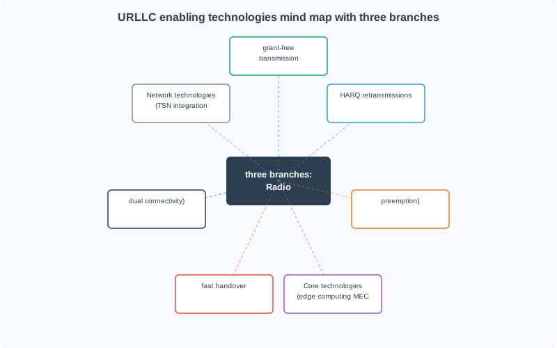
23.7.3 How URLLC Achieves Low Latency
| Technology | Mechanism | Practical Effect |
|---|---|---|
| Mini-slots | Transmit with fewer OFDM symbols than a normal slot | More scheduling opportunities for urgent traffic |
| Configured/grant-free uplink | Let selected devices transmit without a fresh scheduling request | Reduces access delay for small predictable payloads |
| Preemption | Give urgent traffic priority over lower-priority traffic | Protects control traffic when capacity is constrained |
| MEC | Process at local edge instead of distant cloud | Removes wide-area internet round-trip delay |
| Dual connectivity/redundancy | Use multiple radio paths or duplicated packets where justified | Improves resilience during fades or mobility events |
23.7.4 URLLC Use Cases
| Application | Typical Network Budget | Reliability Concern | Example |
|---|---|---|---|
| Factory automation | Single-digit to tens of ms, depending on loop | Missed coordination or unsafe stop | Robot coordination, AGVs |
| Vehicle guidance | Low-latency local safety messages | Handoff and congestion during movement | V2X or site vehicle control |
| Medical robotics | Strictly bounded local loop; remote operation needs additional safeguards | Delay, jitter, and fail-safe behavior | Assisted robotic control |
| Power grid | Fast local protection path | Fault isolation before equipment damage | Protection relays |
23.7.5 URLLC vs Other Slice Types
| Factor | URLLC-Style Service | eMBB | mMTC |
|---|---|---|---|
| Optimized for | Low latency plus high reliability | Throughput | Device density |
| Typical latency focus | Bounded control-loop delay | 10-50 ms class user experience | 100 ms to seconds is often acceptable |
| Reliability focus | Low packet-loss probability under engineered conditions | Good user data service | Efficient low-rate telemetry |
| Cost driver | Reserved capacity, edge, redundancy, validation | Bandwidth and data volume | Device count and coverage |
| Use when | Physical safety or major asset loss is plausible | High bandwidth is needed | Many simple sensors report small payloads |
23.8 5G Power Saving for IoT
23.8.1 Power Saving Features
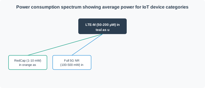
| Feature | Description | Benefit |
|---|---|---|
| eDRX | Extended discontinuous receive cycles | Sleep between paging windows while remaining periodically reachable |
| PSM | Power Saving Mode with long tracking-area update timers | Ultra-low standby for device-initiated reporting |
| WUS | Wake-Up Signal support in compatible networks/devices | Reduces unnecessary wakeups around paging |
| RRC Inactive | Suspended state with retained context | Faster resume than full reconnect with lower power than connected mode |
23.8.2 Power Consumption by Category
23.8.3 PSM and eDRX Configuration
| Parameter | PSM | eDRX |
|---|---|---|
| Wake pattern | Mostly device-initiated | Periodic paging windows |
| Best for | Infrequent uploads, long battery life | Devices that need periodic downlink reachability |
| Battery impact | Lowest standby power | Moderate standby power |
| Reachability | Only when the device wakes or performs tracking-area update | During configured paging windows |
| Deployment note | Timer limits depend on device, network, and subscription | Cycle support depends on operator configuration |
Checkpoint: Power Saving Is a Different Design Question
You now know:
- PSM, eDRX, WUS, and RRC Inactive solve standby and reachability problems, not critical control latency by themselves.
- Low-power telemetry can tolerate seconds or minutes when the application only needs periodic reporting.
- A battery device that needs downlink commands must balance reachability windows against battery life.
23.9 6G Vision for IoT
23.9.1 6G Timeline
6G is best treated as an IMT-2030 planning horizon, not a product you can buy today. ITU-R has defined the IMT-2030 framework and usage scenarios, while detailed radio specifications and commercial deployment plans remain future work.
| Milestone | Year | Description |
|---|---|---|
| 5G-Advanced | 2024-2026 | Release 18/19 era enhancements, including RedCap evolution, NTN, positioning, AI/ML support, and industrial features |
| IMT-2030 framework | 2023 onward | ITU-R framework for 6G usage scenarios and capability families |
| 6G study and specification work | Late 2020s | Research, requirements, candidate technologies, and standards work |
| Early commercial 6G | Around 2030 and beyond | Expected first deployments; scope and performance will vary by region and operator |
23.9.2 6G Performance Targets
| Capability Family | 5G Design Focus | IMT-2030 Direction | IoT Meaning |
|---|---|---|---|
| Throughput | Enhanced mobile broadband | Higher peak and user-experienced data rates | Richer video, sensing data, and digital twins |
| Latency/reliability | URLLC and industrial profiles | More capable low-latency, high-reliability services | More demanding control and coordination use cases |
| Connection density | Massive machine-type communication | Even denser device populations | Larger sensor swarms and asset tags |
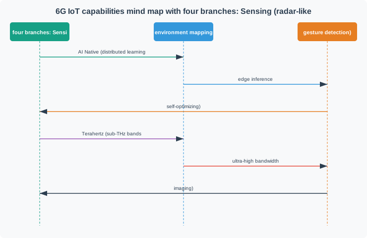
| Sensing | Mostly separate from communications | Integrated sensing and communication | Networks may help localize or detect objects |
| Sustainability | Power-saving modes and efficient radios | Energy efficiency and low-power/ambient IoT | Longer-lived sensors and lower site energy cost |
| AI-assisted operation | Early AI/ML support | AI-native or AI-assisted network operation | Better prediction, optimization, and fault handling |
23.9.3 6G New Capabilities
23.9.4 6G IoT Use Cases
| Capability | IoT Application | Example |
|---|---|---|
| Integrated sensing | Communication infrastructure assists with localization or object detection | Factory zones that track moving assets with radio reflections |
| AI-assisted networks | Prediction, optimization, and anomaly handling in the network | Slices that adapt before a congestion or mobility event |
| High-capacity links | Richer sensing/video data from machines | Industrial inspection with high-resolution feeds |
| Ambient/low-power IoT | Lower-energy tags and sensors | Environmental tags powered by energy harvesting where feasible |
| Non-terrestrial and coverage extensions | Wider-area IoT reach | Remote monitoring beyond dense terrestrial coverage |
23.10 Understanding Check
Scenario: You’re designing connectivity for an autonomous forklift in a warehouse. The forklift must stop within 100 ms of detecting an obstacle. At maximum speed (10 km/h), this gives 28 cm of stopping distance.
Questions:
- What is the maximum acceptable network latency?
- Should you use URLLC or eMBB?
- What reliability level is needed?
23.11 Worked Example: LTE-M Handover Optimization for Fleet Tracking
Scenario: A logistics company has 500 trucks with LTE-M GPS trackers. Drivers report 15-30 second gaps in location tracking during highway driving at 70 mph. The target is gaps under 5 seconds.
Given:
- Fleet: 500 trucks with certified LTE-M modules
- Carrier: LTE-M operator with mobility support
- Current handover failure rate: 8%
- Target: <5 second gaps, <2% failure rate
Analysis:
Current Handover Timeline:
Time Event T=0 s Device connected to Cell A (RSRP: -95 dBm) T=6 s Cell A weakening, Cell B strengthening T=9 s A3 event triggered because neighbor is 4 dB better T=10 s Handover command received T=15 s Handover complete T=18 s Data bearer re-established Problem: 18 seconds from trigger to usable data. At 70 mph, the vehicle travels about 0.35 miles during the gap.
Root Causes:
- A3 hysteresis too high (4 dB), causing a late trigger
- TimeToTrigger too long (480 ms), causing a slow reaction
- Data bearer re-setup adds 3-5 seconds
Optimized Parameters:
Parameter Before After Effect A3 offset 4 dB 2 dB Earlier trigger Hysteresis 2 dB 1 dB Less conservative handover TimeToTrigger 480 ms 160 ms Faster reaction Application-Level Buffering:
// Buffer GPS during handover
void on_gps_fix(gps_position_t pos) {
    if (is_connected()) {
        flush_buffer();  // Send buffered first
        send_position(pos);
    } else {
        buffer_position(pos);  // Store during gap
    }
}
Result:
| Metric | Before | After | Improvement |
|---|---|---|---|
| Handover duration | 18 s | 8 s | 56% faster |
| Failure rate | 8% | 1.5% | 81% reduction |
| Visible gap | 15-30 s | 0 s | 100% (buffered) |
The handover optimization reduced gap duration through parameter tuning. Calculate the distance traveled during handover:
Vehicle speed in feet per second: \[ v = 70 \text{ mph} \times \frac{5{,}280}{3{,}600} = 102.7 \text{ ft/s} \]
Before optimization (18-second handover): \[ d_{\text{before}} = 102.7 \times 18 = 1{,}848 \text{ ft (0.35 miles)} \]
After optimization (8-second handover): \[ d_{\text{after}} = 102.7 \times 8 = 822 \text{ ft (0.16 miles)} \]
GPS visibility gap (30-second update interval): - Before: \(\lceil 18/30 \rceil = 1\) missed update, so a 30 s gap is visible to the dispatcher. - After: \(\lceil 8/30 \rceil = 1\) missed update, but buffering hides the gap from the dispatcher.
With application-level buffering storing GPS fixes during handover, the 8-second gap becomes invisible to the dispatcher. The application shows continuous tracking with interpolation instead of 15-30 second blackouts.
Key Insight: LTE-M defaults are optimized for stationary IoT. For highway speeds, request carrier “high mobility” profile and implement application buffering.
Checkpoint: Roadmap Promises Need Site Evidence
You now know:
- IMT-2030 and 6G capabilities are planning inputs until standards, products, and site validation exist.
- LTE-M handover tuning still needs carrier profiles, application buffering, and measured gaps under motion.
- A future capability does not release a current safety-adjacent deployment without present evidence.
23.12 URLLC Cost-Benefit Decision Framework
URLLC-style capabilities come at a premium: reserved capacity, MEC infrastructure, specialized hardware, integration work, and loaded-site validation. The following framework helps determine whether URLLC is justified for a given IoT application or whether a less expensive alternative (LTE-M, Wi-Fi, or wired) suffices.
Step 1: Determine your actual latency and reliability requirements
Many IoT projects claim “real-time” requirements that, upon analysis, can tolerate 50-200 ms latency. URLLC-style design is needed only when exceeding the latency threshold causes physical harm, financial loss, or system failure.
| Application | Actual latency needed | Actual reliability needed | URLLC justified? |
|---|---|---|---|
| Assisted robotic control | Low single-digit ms for haptic loops | Very high; fail-safe design required | Usually, but keep safeguards local |
| AGV collision avoidance | Often below 10-30 ms after sensing/braking budget | High; site validation required | Often, if wireless is required |
| Factory robot coordination | Usually single-digit to tens of ms | Depends on speed and safety case | Sometimes |
| Smart grid protection relay | Low-latency local fault isolation | High | Often, but compare with wired protection |
| Video quality inspection | Below 100 ms often works | Moderate | Usually no; eMBB or local Wi-Fi may suffice |
| Predictive maintenance alerts | Seconds usually work | Moderate | No; LTE-M/NB-IoT usually suffice |
| Environmental monitoring | Seconds to minutes usually work | Low to moderate | No; LPWAN or cellular IoT usually suffice |
Step 2: Compare URLLC cost against alternatives
Illustrative per-device annual connectivity comparison:
| Technology | Annual cost/device | Latency | Reliability | CapEx per site |
|---|---|---|---|---|
| URLLC private 5G | USD 120-300 | Low single-digit ms when engineered | High, site-specific | USD 80,000-250,000 |
| eMBB 5G slice | USD 40-80 | 10-30 ms class | Good data service | USD 0 if carrier network exists |
| LTE-M | USD 12-36 | 50-200 ms class | Good telemetry service | USD 0 if carrier network exists |
| Wi-Fi 6/6E on-premises | USD 5-15 | Low latency in good RF design | Site-dependent | USD 15,000-50,000 |
| Wired Ethernet | USD 2-8 | Very low and stable | High when installed correctly | USD 200-500 per drop |
Step 3: Calculate break-even
An automotive supplier evaluates private 5G URLLC-style service for 120 AGVs across 3 factory buildings (45,000 m2).
| Option | Cost Element | Value |
|---|---|---|
| Private 5G | 6 gNBs x EUR 35,000 | EUR 210,000 |
| Private 5G | MEC server | EUR 45,000 |
| Private 5G | Annual license | EUR 36,000/year |
| Private 5G | 5-year TCO | EUR 435,000 |
| Industrial Wi-Fi | 90 APs x EUR 1,200 | EUR 108,000 |
| Industrial Wi-Fi | Controller | EUR 25,000 |
| Industrial Wi-Fi | Annual license | EUR 12,000/year |
| Industrial Wi-Fi | 5-year TCO | EUR 193,000 |
| Premium | Private 5G over Wi-Fi | EUR 242,000 |
The supplier chooses the private 5G option only if measured Wi-Fi roaming and interference risk exceed the safety case. A single AGV collision can cost enough in damage and downtime to justify a large connectivity premium, but that conclusion depends on measured site behavior, speed, local safety sensors, and operational procedures.
Key insight: URLLC is justified when the avoided failure risk exceeds the infrastructure premium and the design can be validated under realistic load. For most IoT telemetry, analytics, and monitoring applications, URLLC is overengineered and a simpler technology provides adequate performance at lower cost.
23.13 URLLC Budget Validation
URLLC is useful only when it is tied to a measured end-to-end latency and reliability budget. The radio feature set matters, but the real question is whether the complete control path can meet its deadline under load, mobility, interference, failures, and maintenance conditions.
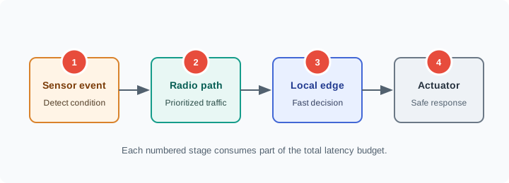
Use the control-loop stages as a budget ledger: sensor detection, radio path, local edge processing, and actuator response all consume time before the application consequence is avoided.
Start with the physical consequence. If delayed packets create safety risk, equipment damage, or unacceptable downtime, then the network design must prove worst-case behavior, not average speed. A warehouse AGV moving at 2 m/s covers 0.5 m in 250 ms, so a collision-avoidance path that promises to stop within that distance cannot spend the full 250 ms on networking. If object detection consumes 15 ms, local planning consumes 20 ms, brake actuation consumes 55 ms, and the safety case reserves 40 ms for margin, only 120 ms remains for communication, queueing, handover, and retry behavior. The radio may advertise single-digit millisecond service, but the release decision must use the remaining system budget.
That is why URLLC is a design pattern rather than a purchasing label. The useful question is: which flows need bounded tail latency, which flows can be ordinary best-effort telemetry, and where is local fallback required if the wireless path misses its deadline? A robot stop command, a protection relay trip, or a remote-control crane movement may need a private 5G slice, local edge breakout, redundant coverage, and timestamped proof. A dashboard update, asset-status message, or batch upload usually does not.
Decision signal: Choose URLLC-style design when validated tail latency and reliability are required for the application consequence, not because a faster service tier sounds better.
23.14 Critical IoT Validation Record
A critical IoT validation record connects the safety or operations case to the network evidence. It should make the release decision auditable when someone asks why public cellular, private 5G, Wi-Fi, wired Ethernet, or local fallback was selected.
Make the record concrete enough that a reviewer can rerun it. For each critical flow, name the device, command, direction, deadline, allowed loss, fallback state, and owner. Then attach the evidence: packet timestamps from the device and edge service, RAN counters or slice policy, handover logs, interference conditions, offered load, packet-loss windows, and the exact firmware and network configuration used.
A statement such as “private 5G is low latency” is not evidence. A record that says “Aisle 7 stop command, 40 ms p99 budget, 10,000 samples during loaded shift, p99 24 ms, p99.9 33 ms, one handover drill, local stop if three samples are missed” can support a release decision.
Separate the approval boundary from the monitoring boundary. Approval proves the site can meet the budget at acceptance time; monitoring proves it keeps meeting the budget after antenna changes, firmware updates, floor-plan changes, and new traffic. Keep dashboards for p95, p99, loss, retransmissions, queue depth, edge-service health, and fallback activations.
| Record field | Evidence to keep | Failure it catches | Release owner |
|---|---|---|---|
| Control-loop budget | Total deadline, sensor time, compute time, actuator time, safety margin, and remaining network budget. | Buying low latency that the application does not need, or missing a deadline the radio cannot fix. | Safety/application owner and systems engineer. |
| Path architecture | Radio profile, QoS/slice behavior, edge location, TSN bridge role, wired fallback, and local stop logic. | Assuming the radio hop proves the full sensor-to-actuator path. | Network architect and edge/platform owner. |
| Tail-latency test | p95/p99 latency, packet loss, handover, interference, congestion, and failure-mode results under realistic load. | Average latency hiding rare events that break safety-adjacent control. | Validation lead and operations owner. |
| Roadmap boundary | What is deployable now, what is 5G-Advanced roadmap, and what is future 6G/IMT-2030 assumption. | Committing a release to features that are not standardized, available, or validated at the site. | Product owner and architecture reviewer. |
Use three release outcomes:
- Approve when evidence shows bounded tail latency, acceptable loss, edge path health, monitoring, and recovery behavior with margin.
- Limit when URLLC is justified only for the critical path and monitoring, analytics, and bulk transfer can stay on ordinary connectivity.
- Reject when the application has no measured budget, no failure consequence, or no validation plan for tail behavior.
23.15 Tail Latency and Control Loops
Average latency is a weak metric for critical IoT. A control loop fails when rare delay, packet loss, handover, or queueing pushes a response past the deadline. That is why p99 behavior, failure-mode testing, local fallback, and safety margin matter.
Work the latency arithmetic from the tail. Suppose a motion-control support flow has a 40 ms network budget after sensing and actuation are removed. If unloaded tests report an 8 ms average but a 55 ms p99 during handover, the system still fails the requirement because one packet in a hundred can arrive after the safe window. Reliability targets have the same shape: a one-hour demo with no drops does not prove a 99.999% requirement unless the test volume, confidence level, and failure model are stated. URLLC validation therefore combines timestamped probes, packet-loss accounting, mobility drills, traffic bursts, and fault injection instead of relying on a single speed-test number.
5G features can reduce risk: mini-slots can shorten scheduling opportunities, configured uplink can reduce request delay, preemption can prioritize urgent traffic, edge processing can avoid cloud round trips, and TSN integration can align wireless paths with industrial schedules. Each feature moves one part of the distribution, but none removes the need to validate the complete site path. A configured grant can help the uplink while the downlink command still waits behind a congested queue. Edge placement can remove WAN delay while the edge service itself becomes the bottleneck.
The robust design is layered. Keep the control function close to the device, reserve radio and transport resources for only the critical traffic class, give noncritical telemetry a separate path, and define a safe local state when the network misses consecutive deadlines. Then prove both the happy path and the degraded path: a normal command should meet the p99 budget; a congested or handover case should either stay within margin or trigger reduced speed, local stop, or wired fallback before the hazard grows.
Checkpoint: Validation Closes the Loop
You now know:
- Cost only matters after the technical path can meet the measured deadline with margin.
- p95, p99, loss, handover, queue depth, and fallback activation belong in the release record.
- Approve, limit, or reject the design based on validated tail behavior, not average latency alone.
23.16 Summary
URLLC-style design targets bounded latency and high reliability for mission-critical IoT
URLLC technologies include mini-slots, configured uplink, preemption, redundancy, and MEC
Power saving (PSM, eDRX) enables 10+ year battery life for NB-IoT/LTE-M
6G/IMT-2030 is a future roadmap, not a current product specification
6G capability themes include integrated sensing, AI-assisted operation, sustainability, and wider coverage
LTE-M mobility optimization requires tuned A3 parameters and application buffering
23.17 Concept Relationships
23.18 See Also
23.19 Try It Yourself
Common Pitfalls
URLLC radio targets are not the same as application round-trip time. An industrial control loop includes sensor sampling, local processing, uplink, edge compute, downlink, actuator response, and safety margin. Design control systems for achievable end-to-end latency, not just air-interface specs.
Strict low-latency requirements usually cannot be met with distant cloud-hosted control logic. A control command traveling from the device to a remote cloud region and back can add tens of milliseconds of internet round-trip time. URLLC-style deployments generally need Multi-access Edge Computing (MEC) at the enterprise premises or close to the RAN. Verify MEC availability and latency in the target deployment zone before committing to URLLC-based architectures.
PROFIBUS, PROFINET IRT, and EtherCAT are used in industrial environments where equipment, safety certification, and timing behavior are already validated. 5G URLLC can complement but not automatically replace wired fieldbus for safety-critical functions, hard real-time motor control, and equipment with existing wired interfaces. Design 5G URLLC for mobility, flexible cells, and wireless bridges while maintaining wired connections where certification requires them.
High-reliability low-latency service consumes more radio and edge capacity than best-effort data service. Worst-case channel conditions, redundancy, and priority scheduling reduce spectral efficiency. Factor URLLC resource costs into TCO analysis; a small number of critical devices can consume capacity that would otherwise support many best-effort devices.
23.20 What’s Next
| Chapter | Focus Area | Link |
|---|---|---|
| Private 5G Networks | Enterprise deployment guide with URLLC-style slice configuration | Private 5G Networks |
| 5G-Advanced Overview | 5G evolution timeline from Release 15 to Release 18 | 5G-Advanced Overview |
| Cellular IoT Applications | Real-world cellular IoT deployments and industry use cases | Cellular IoT Applications |
| 5G Network Slicing | Virtual network architecture for diverse IoT service types | 5G Network Slicing |