17 Lab: LTE-M Power Modes and Coverage
17.1 Start With the Story
The LTE-M lab is a controlled version of a field device waking up, attaching, sending, listening, and sleeping. Each state costs time and current, so the lab should make the trade-off visible.
Start simple: run one message through the state machine and record how coverage and power mode change the outcome.
17.2 Learning Objectives
After completing this lab, you should be able to:
- Trace an LTE-M device from cell search through registration and packet-data readiness.
- Explain why LTE-M is often selected for mobile or more responsive IoT devices.
- Compare PSM and eDRX as design choices rather than fixed battery-life guarantees.
- Decide when a compact uplink should use a control-plane style path and when a user-plane data session is a better model.
- Identify what must be measured on real hardware before trusting a simulated LTE-M result.
- Build a troubleshooting note that separates radio, SIM, packet context, application, and power-state evidence.

Phoebe’s Why
An antenna does not create power; it redistributes a fixed amount of it in space, and a directional antenna’s gain is exactly that redistribution – more power density in one direction, paid for by less everywhere else. That trade is a good deal for a fixed gateway that always points at the same tower. It is a bad deal for the fleet tracker this lab tests, because a moving vehicle’s heading relative to the serving cell keeps changing, so a beam mounted rigidly to the chassis sweeps past the tower rather than staying locked onto it. The lab’s own antenna-placement and route-walk gates exist because the RF path is not fixed the way it is on a bench; a gain figure measured with the antenna aimed correctly says nothing about the moment, seconds later, when the vehicle turns and the same antenna is aimed somewhere else entirely.
The Derivation
Effective isotropic radiated power combines conducted power and antenna gain:
\[\mathrm{EIRP\,(dBm)} = P_t\,\mathrm{(dBm)} + G\,\mathrm{(dBi)}\]
Gain redirects a fixed transmit power into a narrower solid angle \(\Omega\) (steradians):
\[G = \frac{4\pi}{\Omega}\]
A common engineering estimate (Kraus) relates gain to the two half-power beamwidths \(\theta_E,\theta_H\) in degrees, so more gain forces a narrower patch of sky:
\[G \approx \frac{41253}{\theta_E\theta_H}\]
Off-boresight, EIRP falls by the antenna’s own pattern, not by anything the network changed:
\[\mathrm{EIRP}_{off\text{-}axis} = P_t + G - L_{off\text{-}axis}\]
Worked Numbers: Puck Versus Patch on a Moving Chassis
The lab does not fix a device power class or antenna, so take standard, catalog-typical figures: an LTE-M Category M1 power-class-3 module (23 dBm conducted, 200 mW) with either a 2 dBi omni “puck” antenna or an 8 dBi directional patch.
- Omni EIRP: \(23 + 2 = 25\) dBm, the same in every heading
- Patch EIRP on-axis: \(23 + 8 = 31\) dBm – 6 dB stronger when pointed exactly at the tower
- Patch beamwidth from the Kraus estimate (\(G_{lin} = 10^{0.8} = 6.31\)): \(\theta_E\theta_H \approx 41253/6.31 = 6{,}540\ \mathrm{deg}^2\), so a symmetric beam is \(\theta \approx \sqrt{6{,}540} = 80.9\) degrees – covering only \(80.9/360 = 22.5\%\) of possible headings
- Off-axis, with a catalog-typical 15 dB pattern rolloff beyond the main lobe: \(\mathrm{EIRP} = 23 + 8 - 15 = 16\) dBm – 9 dB weaker than the plain omni’s 25 dBm in every one of those directions
- 9 dB is a \(10^{-9/20} = 0.355\times\) power ratio – roughly a third of the omni’s link budget, for 77.5% of the vehicle’s possible headings
The patch is not a bad antenna; it is the wrong antenna for a chassis that rotates. This is exactly why the lab’s antenna-placement gate has to be walked on the actual route, in every direction of travel, rather than approved from one bench measurement aimed at the strongest reading.
Overview: LTE-M Claims Need A Session Record
An LTE-M lab is useful only when it records the whole session, not just a successful message. The evidence chain starts with cell search, SIM or eSIM identity, registration, RRC state, packet context, payload transfer, mobility condition, power mode, and recovery behavior.
The decision is not "LTE-M works here." The decision is whether this module, antenna, operator service, subscription, payload pattern, route, and service-delay target can support the product behavior with reviewable evidence. A field tracker, for example, may need proof that it can find service after boot, register with the intended SIM profile, create the packet context, upload an exception event, survive a weak-signal segment, and avoid reporting stale location after a reset. If the lab records only the one successful upload, it cannot answer those deployment questions.
Start the lab by naming the claim being tested. "LTE-M can support our moving asset tracker" is too broad. A useful claim is narrower: "this hardware can register on the selected service, send a compact exception payload while moving, enter the chosen low-power mode, and recover without confusing old and new events." That wording tells the team what evidence to save and what failure would invalidate the result.
Keep the first pass small but complete. One run should show the modem state before registration, the identity and service profile used, the signal and cell observations, the packet path, the application acknowledgement, the sleep or idle choice, and the retry or recovery behavior. Later runs can add route variation, antenna placement, enclosure effects, and operator differences. The habit is the same: every LTE-M result should be tied to the exact session that produced it.
Practitioner: Build The Route And Power Record
For each run, save the firmware version, LTE-M category, operator, band, SIM profile, APN or packet context, signal metrics, RRC transition, payload ID, cloud receipt, movement condition, retry count, and current trace. Keep compact heartbeats, exception alerts, and diagnostic uploads as separate cases.
Run the lab as gates: first registration, then one small payload, then movement or weak-coverage stress, then PSM/eDRX behavior, then recovery after reset, outage, or stale data. A pilot should not pass because one bench message succeeded. Each gate should have an expected observation and a stop condition. If registration works only after repeated manual resets, if the APN is corrected by hand, if the cloud receipt cannot be matched to the payload ID, or if the current trace omits retry energy, the record is still a finding rather than an approval.
Separate route evidence from bench evidence. On the bench, the team can verify commands, packet-context setup, payload formatting, TLS or socket behavior, and baseline current. On a route or site walk, the team must also capture serving-cell changes, signal margin, failed attach attempts, reconnection time, buffering policy, and whether the application treats delayed data as stale. A good record lets a reviewer see whether the product failed because of the radio, SIM profile, antenna, packet context, firmware state machine, cloud service, or power-mode decision.
Use a simple run sheet. For each row, record the scenario, location or route segment, start state, expected service behavior, modem events, payload result, sleep-mode result, measured current window, exception handling, and owner decision. Mark a row "pass" only when the evidence supports that exact scenario. Mark it "needs field work" when the bench result is plausible but the mobility, coverage, roaming, or power-mode condition has not yet been tested. That distinction prevents a tidy lab demo from becoming a premature production claim.
Under the Hood: Reachability Changes With Radio State
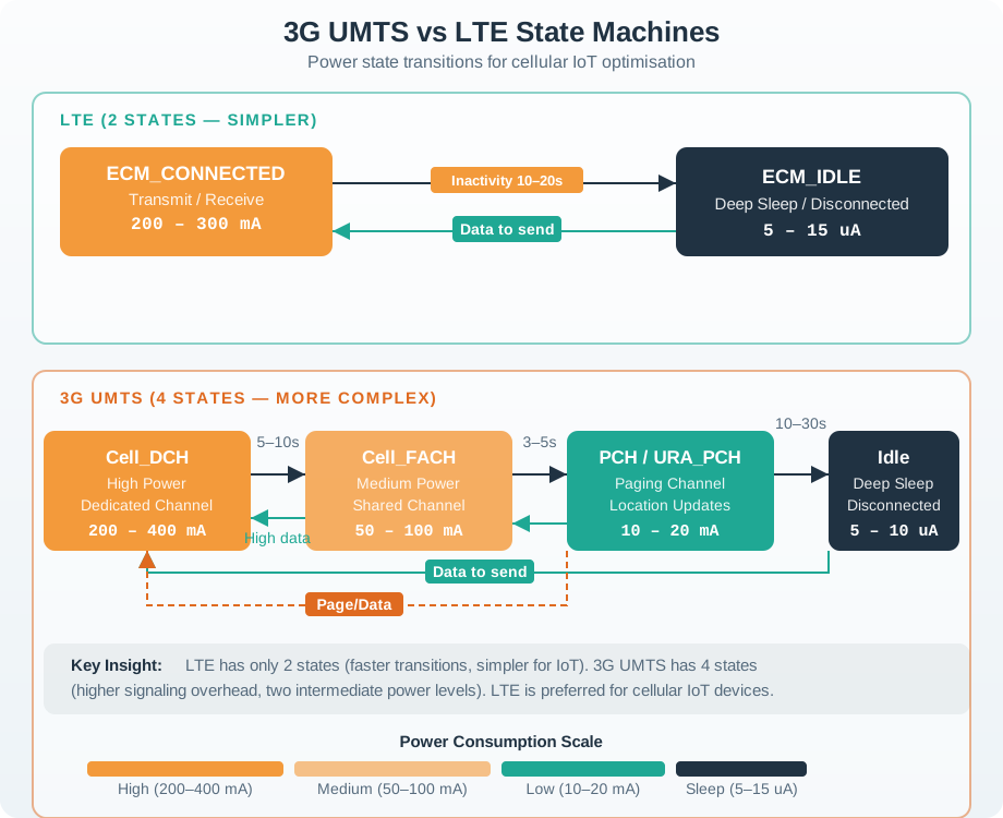
LTE-M behavior changes as the device moves between search, camped, registered, idle, connected, paging, and sleep states. PSM can save energy while making downlink wait for the next wake. eDRX can preserve periodic reachability while adding paging delay. A normal data session can handle richer traffic, but it costs setup, radio time, and retry energy.
That hidden state is why a fleet tracker needs route records, stale-location rules, bounded retries, and separate diagnostic budgets. Otherwise the lab may prove a message path while missing the conditions that drain the battery or deliver old data as if it were current. The radio may appear quiet from the application layer while it is still searching, camping, authenticating, waiting for paging, retrying a packet context, or reconnecting after a coverage gap.
PSM and eDRX are negotiated behaviors, not local switches with guaranteed results. The network, subscription, module firmware, and application timing all affect whether the requested timers are accepted and whether the device is reachable when the product expects it to be. A sleep-heavy sensor can tolerate delayed downlink if the application is designed around scheduled reports. A moving tracker, alarm device, or support tool may need a shorter reachable window, a powered active mode, or a local rule that buffers and labels events until the packet path is healthy again.
The current trace should therefore cover the whole state machine, not only the radio burst. Include host-microcontroller activity, sensor wake time, modem boot, search, registration, payload transfer, retry windows, idle or paging time, and deep sleep. Also record what the application does with old data after reconnecting. The technical goal is to prove that the state transitions match the product promise: messages are current enough, retries are bounded, battery assumptions include failure cases, and recovery does not silently turn stale telemetry into a fresh event.
- LTE-M / eMTC / Cat-M1: A 3GPP cellular IoT technology based on LTE, commonly used when connected mobility, richer payloads, or more responsive behavior matters.
- RRC (Radio Resource Control): The radio-control state used to manage connection setup, idle behavior, measurements, and connected operation.
- EPS bearer / packet data context: The network data session that gives the device an IP path through the LTE packet core.
- Control-plane optimization: A method for small data where payloads can be carried with signaling to reduce setup overhead in supported deployments.
- User-plane data: A normal IP data path that is better for larger payloads, frequent transfers, or longer sessions.
- PSM (Power Saving Mode): A deep sleep state that reduces energy use but makes the device unreachable until it wakes or performs a network update.
- eDRX (Extended Discontinuous Reception): A paging-cycle mode that trades reachability delay for lower power without sleeping as deeply as PSM.
- Connected mobility: The ability to move between cells while maintaining service continuity, subject to network, module, subscription, and coverage behavior.
An LTE-M device has to do more than “get signal.” It must find a suitable cell, register with the network, prove SIM or eSIM identity, create a data context, send payloads, choose when to sleep, and recover when the radio environment changes.
This lab treats those actions as a state machine. Each experiment changes one design pressure: movement, wake-up delay, payload size, or failure handling. The point is to understand the behavior you would later test with a real module, SIM profile, antenna, and operator network.
17.3 Prerequisites
Before starting this lab, review:
- Cellular IoT Fundamentals for LTE-M, NB-IoT, PSM, eDRX, and coverage concepts.
- Cellular IoT Implementations for modem bring-up, APN configuration, AT-command state machines, and production evidence.
- Cellular IoT Deployment Planning for site measurement, pilot gates, and fleet operations.
- Basic state-machine programming concepts.
17.4 Lab Model
The lab uses five reusable states. A real module will expose different command names and event codes, but the design logic stays similar.
This page does not claim to replace a modem, carrier account, or RF test. It is a teaching lab for the state machine. Real acceptance still requires final hardware, antenna, enclosure, SIM profile, operator coverage, firmware, and measured current traces.
17.5 Experiment 1: Registration Trace
Start with the simplest successful trace. Read each step as a state transition your firmware must be able to log.
- SEARCHING: modem scans supported LTE-M bands and reports candidate cells.
- CAMPED: modem selects a suitable cell and can monitor network information.
- REGISTERING: modem starts network registration and SIM-based authentication.
- REGISTERED: modem is accepted for service by the selected operator or roaming partner.
- DATA_READY: packet context is configured, activated, and ready for a small test payload.
Write down the minimum log fields you would keep for this trace: radio mode, registration result, signal metrics, SIM/profile state, APN, packet context result, IP/session result, and timestamp. If your firmware cannot record those fields, field support will be guessing.
17.6 Experiment 2: Mobility and Handover
LTE-M is often chosen for devices that move across cells. Do not reduce that to a single speed number. The real question is whether the device can keep its service behavior within the application’s tolerance while signal quality, cell selection, and network policy change.
Serving-cell quality
Track signal strength and quality trends, not only a one-time signal reading.
Neighbor-cell measurements
Record whether the modem can see stronger candidate cells before the serving cell becomes unusable.
Application continuity
Check whether payload delivery, buffering, and retry behavior stay within the service requirement during movement.
17.6.1 Mobility Lab Questions
- Which payloads can be delayed until the device reaches a stable cell?
- Which alerts must be sent immediately while moving?
- How will the device behave when the network does not permit the expected mobility behavior?
- What local buffering rule prevents stale location data from being sent later as if it were current?
17.7 Experiment 3: PSM or eDRX
PSM and eDRX are not “battery life buttons.” They are negotiated behaviors that must fit reachability and energy requirements.
Run it: Use the energy quiz below to reason about the mode trade-off instead of picking from the table alone. Open the Budget and Cycle views and press Play or Step to watch how active, transfer, retry, idle or paging, and sleep time add up across one duty cycle, then use Reveal to check each answer and the Design Rule panel to confirm your logic. Bring that reasoning back to this experiment: decide PSM, eDRX, or always-ready only after the whole measured duty cycle, not the wake interval alone, supports the reachability and energy requirement.
Do not approve a power mode from configuration alone. Measure boot, registration, payload transfer, retries, idle, paging, host sleep, and modem sleep as one duty cycle.
17.8 Experiment 4: Control Plane or User Plane
Payload path selection depends on message size, frequency, security needs, module support, and operator support.
Small and occasional
Consider for compact payloads where supported, especially when creating a full data session would cost more signaling than the data itself.
Larger or frequent
Use for larger telemetry, application sessions, TLS-heavy traffic, diagnostics, and firmware maintenance.
Let measurements decide
Compare delivered bytes, latency, retry count, network acceptance, and current trace before standardizing a path.
Classify these messages:
- A periodic location heartbeat with a compact payload.
- A diagnostic log after a field fault.
- A firmware update manifest.
- A life-safety alert where the device may be moving.
For each one, write the likely path, acceptable delay, retry rule, and whether stale data should be discarded.
17.9 Experiment 5: Voice-Capable Service
LTE-M is sometimes used in designs that need voice-like service, push-to-talk behavior, emergency calling, or an intercom workflow. Treat this as a deployment feature, not a guaranteed default.
Module, operator, subscription
Voice-capable service depends on the module firmware, IMS support, operator configuration, SIM profile, and commercial plan.
What if voice fails?
Define whether the device sends location, raises a data alert, retries, or escalates through another channel.
Call plus mobility
Validate behavior while moving, during weak-signal periods, and across the sites where the service is actually used.
17.10 Lab Scenario: Fleet Tracker
Assume a fleet tracker sends a compact heartbeat while moving, stores richer diagnostic events locally, and raises immediate alerts for theft, crash, or route deviation.
17.11 Compact Lab Pseudocode
This short pseudocode is the model for the exercises. Real firmware should also handle URCs, timeouts, SIM faults, APN faults, DNS/TLS failures, and modem resets.
state = SEARCH

on cell_found:
  state = REGISTER

on registered:
  state = DATA_READY

on small_payload and supported:
  send_control_plane_style()

on large_payload or session_needed:
  send_user_plane_style()

on movement_event:
  record_signal_and_delivery()

on idle_window:
choose_psm_or_edrx()The names above are intentionally generic. Standard AT commands exist for many modem functions, but module vendors add their own socket, MQTT, TLS, PSM, eDRX, and diagnostic commands. Use the module’s current command manual and keep the state machine testable.
17.12 Quick Check: LTE-M Lab Decisions
Run it: Reason the selection out in the decision workbench below before you answer the check. Load the Fleet tracker scenario, set Mobility while connected to Moving while connected and Latency target to Seconds matter, then press Step through the decision stages and read the “How to read the result” panel to see the recommendation lean toward LTE-M. Now switch Mobility to Stationary / fixed and watch the result shift back toward NB-IoT. Use that observed contrast to justify why LTE-M is the defensible first technology for a moving, responsive tracker.
17.13 Real Hardware Checklist
Before turning this lab into a field pilot, verify each item with the intended device.
Firmware and bands
Confirm LTE-M bands, firmware version, AT command support, power modes, and socket/TLS behavior.
Provisioning
Confirm profile state, operator access, roaming policy, APN, authentication, suspension, and replacement workflow.
Installed RF path
Measure signal and delivery with the final antenna, enclosure, mounting point, and route or site category.
Current trace
Measure boot, search, registration, transfer, retry, idle, paging, and sleep as one cycle.
Data contract
Define payload schema, stale-data rules, retry limits, alert priority, TLS behavior, and update budget.
Field evidence
Log enough diagnostics to distinguish SIM, APN, registration, signal, cloud, and power-state failures.
17.14 Common Pitfalls
The lab teaches state transitions, but real RF behavior depends on the operator network, antenna, enclosure, route, nearby cells, and deployment policy. Do not approve hardware without field measurements.
PSM can be useful, but a device in deep sleep cannot receive an urgent command until it wakes. Start with service-level delay requirements, then choose the power mode.
Mobile devices often collect more data than the service needs. Prioritize alerts, compact heartbeats, and stale-data discard rules before uploading every sample.
LTE-M availability, roaming, PSM/eDRX behavior, compact data support, and voice-capable service vary by operator and subscription. Validate the exact service profile used in the pilot.
17.15 Concept Relationships
17.16 See Also
17.17 Try It Yourself
17.18 Summary
- LTE-M lab work should focus on state-machine evidence: search, registration, packet context, transfer, sleep, movement, and recovery.
- LTE-M is a strong first candidate when connected mobility, reachability, richer payloads, or voice-capable service may matter, but those features must be verified in the target network.
- PSM and eDRX must be chosen from service delay requirements and measured current traces, not from headline sleep-current claims.
- Compact payload paths and normal data sessions solve different problems; measure bytes, latency, retry behavior, and network acceptance before standardizing either path.
- A production pilot needs real module firmware, SIM/eSIM provisioning, antenna placement, operator support, route or site testing, and supportable diagnostics.
17.19 Key Takeaway
LTE-M labs should measure attach time, signal quality, data transfer, sleep behavior, and reconnection rather than only proving a message can be sent. Those measurements determine battery life and field reliability.