20 5G Network Slicing for IoT
20.1 Overview: A Slice Is a Managed Service Profile
Picture a yard with cameras, moving vehicles, and small asset tags. All use one 5G system, but their jobs differ. Video needs steady upload. A vehicle command needs a fast, safe path. Tags need simple reports and long battery life.
Latency means the time from sending work to receiving the needed result. Telemetry means time-stamped reports about device state and events. A network slice is a managed service profile over shared network parts. It can give workloads different treatment. It is not a separate set of towers, and it is not a promise of perfect isolation. The device, account, radio, core path, application, monitoring, and operator terms must all support the profile.
Check one workload at a time:
- What job uses the slice?
- Which device class uses it?
- Is that device allowed on it?
- Which path carries its data?
- What result must stay fast?
- What load was used in the test?
- Which signal shows a weak service?
- What happens when the slice is lost?
- Who owns that fallback?
- What change forces a loaded retest?
A colored lane on a diagram is only a design idea. Practitioner writes the service and test record. Under the Hood separates selection, scheduling, routing, and isolation. Those details may expose shared limits. They never make an untested service label proof of the field job.
5G network slicing lets one 5G system present different logical service profiles over shared radio, transport, core, edge, and operations resources. For IoT, that matters when cameras, mobile gateways, safety-related control paths, and dense telemetry fleets need different treatment without building a separate physical network for every workload.
A slice is not a promise of perfect isolation. It is a configured service path that depends on device and SIM support, subscription policy, S-NSSAI authorization, 5G Core functions, RAN scheduling behavior, edge placement, monitoring, and the operator or private-network contract. The design question is whether those layers have been validated for the workload, not whether the slice has an impressive label.
For example, a logistics yard might group gate cameras, automated vehicle control, and pallet tags into three service profiles. The camera profile cares about sustained uplink capacity and backhaul congestion. The control profile cares about loaded-site latency, local breakout, fallback behavior, and who is paged when the path degrades. The tag profile cares about attach storms, battery-friendly reporting, and whether the platform can absorb bursts after a shift change. Those three profiles can share towers, fiber, and core functions, but they need separate acceptance evidence because a pass for video throughput does not prove control-loop latency or dense-device behavior.
The practical shortcut is to treat the slice as a service boundary with a record, not as a colored lane on a diagram. The record names the workload, allowed slice identifier, tested device class, radio condition, user-plane route, application endpoint, monitoring signal, and fallback owner. If any of those entries is blank, the slice is still a design intent rather than an operationally proven IoT service.
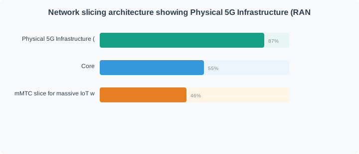
Bring Figure 20.1 into the review before overview: a slice is a managed service profile. The diagram identifies 5G network slicing architecture showing eMBB, URLLC-style, and mMTC-style logical service profiles over shared 5G infrastructure, which the decision record must preserve.
Read Figure 20.1 from the shared 5G infrastructure at the bottom upward: one physical network carries three logical service profiles, an eMBB slice for video, AR and gateways, a URLLC-style slice with engineered latency, and an mMTC-style slice for dense, low-rate devices. The point of the overview is that a slice is a managed service profile: it describes a complete service chain and who owns each part of it, not just a radio setting.
20.1.1 Throughput Profile
Video, AR support, and high-rate gateways usually need an eMBB-style profile with enough capacity and backhaul for sustained traffic.
20.1.2 Control Profile
Low-latency control needs stronger engineering evidence: loaded radio tests, local routing where needed, monitoring, and application safety behavior.
20.1.3 Telemetry Profile
Dense low-rate devices usually need efficient access, battery-aware behavior, simple payload paths, and predictable management at scale.
20.1.4 Release Boundary
Approve a slicing design only when the record ties workload needs to an allowed slice, a tested radio/core path, an application destination, monitoring signals, and a recheck trigger. A diagram or requested S-NSSAI does not prove the service behavior by itself.
20.2 Practitioner: Build the Slice Validation Record
Start from the workload and work downward. A camera slice, a control slice, and a telemetry slice may share the same site, but they should not share the same acceptance record. Each workload needs evidence for the devices that request the slice, the network that authorizes it, and the application path that receives the traffic.
A compact validation record is usually enough for a first release. For a warehouse deployment, write one row for the video profile, one for vehicle control, and one for sensors or tags. In each row, record the device firmware and SIM policy used in the test, the allowed S-NSSAI, the busy-hour radio condition, the UPF or edge anchor, the application endpoint, the observed bottleneck, and the rollback or fallback action. That makes tradeoffs visible: a carrier-managed slice may cover multiple yards quickly, while a private deployment may give the site team stronger proof over local radio, local core, and edge placement.
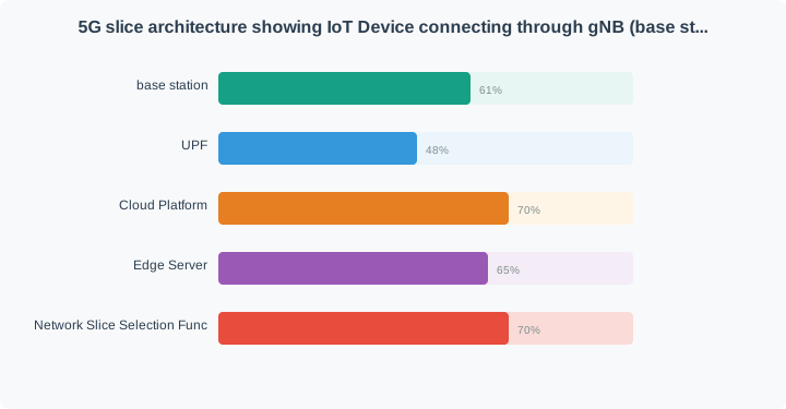
Trace Figure 20.2 from the IoT UE through the gNB, then separate the Control plane functions from the UPF and application data route. AMF, SMF, and NSSF establish or select the session context; UPF carries user traffic toward edge or cloud services. A slice validation record must therefore join policy evidence with an observed packet path and application outcome.
At IoT UE, Figure 20.2 states the first fact; gNB supplies the related fact, and Control plane identifies what constrains their use. This is how the figure communicates 5G slicing control and user plane functions connecting devices through gNB, AMF, SMF, NSSF, UPF, edge, cloud, and IoT platforms. It anchors practitioner: build the slice validation record in observable conditions.
Next inspect deployment ownership in Figure 20.6. Private RAN and Local edge sit inside the standalone private model, while hybrid and carrier-slice arrangements move selected responsibilities toward the operator. The validation record should name who controls spectrum, RAN, core, edge, and incident response so a topology label cannot hide an unowned service boundary.
Standalone private, Private RAN, and Local edge are the three concrete cues in the diagram in Figure 20.6. Their relationship presents private and carrier 5G deployment models showing standalone private 5G, hybrid private 5G, and carrier network slice options. The chapter carries that evidence into practitioner: build the slice validation record so later teams can reproduce the reasoning.
20.2.1 Private or Carrier Managed?
Choose a private deployment when local control, data boundary, site-specific radio design, or edge placement is the main risk. Choose a carrier-managed slice when coverage footprint, operator operations, or a lighter site deployment matters more. In both cases, write down what the owner can verify directly and what must be proven through the provider's evidence.
20.3 Under the Hood: Selection and Isolation Are Separate
Slice selection and slice isolation are related, but they are not the same mechanism. Selection decides which slice a device may use. Isolation decides how strongly that slice is separated in radio scheduling, transport, core routing, management, and failure handling.
Selection begins before user traffic is flowing. The device may include requested slice information during registration or session setup, but the network still compares that request with subscription policy, allowed NSSAI, roaming rules where applicable, and slice availability at the serving location. Core functions then steer the session toward an allowed service path: the access and mobility layer handles registration context, session management builds the data session, slice selection support helps choose an allowed slice, and the user plane carries packets toward the chosen edge or cloud endpoint.
Isolation is proven later and under load. A device can be placed on the intended slice and still miss its application target if the radio scheduler is congested, QoS flow mapping is weak, the transport path shares a bottleneck, the edge anchor is remote, or the application queue is saturated. That is why a slicing test needs two columns: selected slice and delivered behavior. The first column proves authorization and steering; the second proves capacity, latency, loss, jitter, monitoring, and fallback behavior for the workload while other profiles are active.
A useful under-the-hood lab therefore runs at least two competing traffic profiles at the same time. Keep a telemetry background load active while a control flow is tested, then add a video or gateway burst and watch which evidence changes first. If only the application timestamp moves, investigate the endpoint queue. If radio retransmissions, scheduler delay, or QoS counters move first, the slice needs resource-treatment evidence before the application team is blamed.
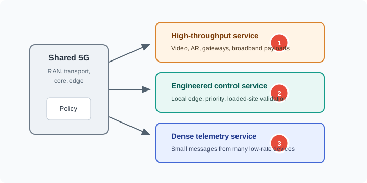
For under the hood: selection and isolation are separate, the useful question is not what the technology is called but what Figure 20.4 labels: network slicing service profile diagram showing shared 5G policy feeding high-throughput, engineered control, and dense telemetry service profiles.
Start Figure 20.4 at the shared 5G system on the left, where the slice request is checked against the subscription policy and the allowed NSSAI, and follow the core’s steering into the three profiles on the right: high-throughput, engineered control and dense telemetry. Under the hood, selection and isolation are separate steps. Selection proves the slice was authorised and steered; isolation is only proven when the delivered behaviour is measured under load, which is why the test needs both columns.
20.3.1 Loaded-Site Recheck
If a control workload misses its target during a busy site test, do not assume the NSSF selected the wrong slice. First separate selection evidence from isolation evidence: confirm the allowed slice, then check radio load, QoS flow mapping, edge routing, application behavior, and fallback controls.
20.4 Start With the Story
Network slicing is easiest to understand as a service promise. One IoT workload may need cheap periodic telemetry, another may need protected latency, and another may need isolated industrial traffic.
Start simple: define the workload promise first, then ask whether a slice, operator contract, and monitoring evidence can actually enforce it.
20.5 Private 5G Networks for IoT
20.5.1 Overview: Private 5G Is a Boundary Decision
A private fifth-generation (5G) network brings cellular service inside one site or organization. It is not simply faster Wi-Fi. The organization takes on, or closely manages, the radio, device identities, traffic rules, monitoring, and daily operation.
Latency means the delay between an action and its result. Do not begin by asking, "Is it 5G?" Ask which duties move to the site and who can operate them. The network is justified only if this control solves a real problem with coverage, movement, security, latency, or the data path.
Start with the workload and owner. Guided carts, cameras, tablets, sensors, and controllers can need different coverage and traffic priority. They can also need different local routes, identity rules, and incident response. Record what the organization owns, what a managed provider runs, what a public operator controls, and what the application team measures.
Compare simpler options too. Wi-Fi, Ethernet, public cellular service, LTE-M, wired industrial networks, or a local low-power network may meet some needs with less work. Private 5G earns its place only when evidence shows that its local control, movement support, security, or data route solves a specific site problem.
Use Figure 20.5 to map ownership. Device modules connect to the site’s radio access network (RAN). The transport path carries traffic to the core, which manages identities and sessions. A user plane function (UPF) routes application data. The Evidence side covers the core, UPF, local applications, business systems, and operating team. These named duties make control testable.
Follow one observed message through three checkpoints: Devices, modules, and Evidence. Record its path through the private RAN, transport, core, UPF, local application, and business system. The operating evidence must show who owns each handoff.
Radio Boundary
Record the private RAN and antenna placement. Add radio approval, coverage, movement between cells, interference response, and site evidence.
Core Boundary
Record device identity, policy rules, sessions, and local data routing. Add monitoring, backup, and upgrade ownership.
Application Boundary
Measure delay from the device to its app. Record local app placement, firewall and name-service paths, login cost, and failure behavior.
Operations Boundary
Runbooks, change windows, incident response, SIM or eSIM lifecycle, patching, rollback, and support handoff.
Review private 5G as an operating model, not as a product label. A single connected device does not prove spectrum fit, core readiness, application latency, mobility, or support readiness.
20.5.2 Practitioner: Compare Deployment Models by Responsibility
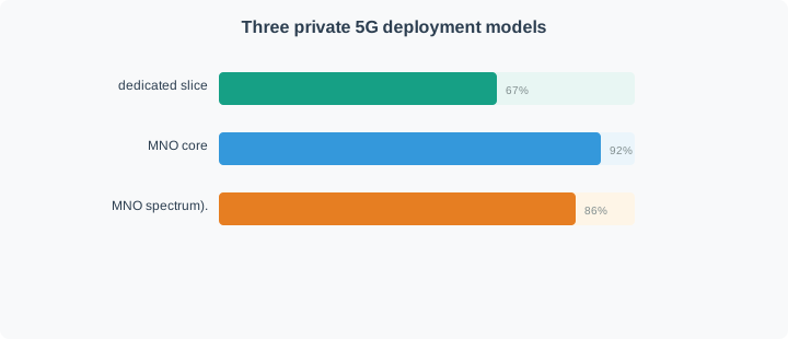
Private 5G labels vary across vendors and countries. Compare candidate models by who controls spectrum, RAN, core, SIM or eSIM identity, user-plane breakout, edge application placement, support, and failure response.
A defensible practitioner: compare deployment models by responsibility starts with the relationships in Figure 20.6, where standalone private, hybrid private, and carrier-slice 5G models compared by how ownership of the RAN, core, edge, and spectrum splits between enterprise and operator is made explicit for review. Inspect Private RAN beside Local edge before the next claim.
Read Figure 20.6 from standalone private 5G through hybrid private 5G to the carrier network slice. More responsibility shifts toward the operator across these panels. Use the bottom row to record ownership and distinguish site checks from evidence the provider must supply.
Spectrum evidence is part of this comparison. The review should document the local authorization path, permitted equipment, power and installation limits, interference response, and the owner who handles spectrum events.
Separate mobile control, video, telemetry, safety support, staff devices, and fixed equipment.
Decide what must be local, managed, or operator provided before choosing a vendor model.
Measure device-to-application behavior with representative devices, routes, load, and failures.
Name who owns identity, patches, rollback, monitoring, spectrum events, and incident response.
20.5.3 Under the Hood: Release Gates Tie Radio, Core, and Operations Together
A private 5G release should fail closed when the evidence is incomplete. Low-latency, local-breakout, security, and mobility claims are valid only when the complete path has been measured and the owner of each failure mode is named.
The running service decision reaches a visual proof point at Figure 20.7, which sets out private 5G validation gates from requirements through spectrum, site survey, pilot, application path, operations, and rollout decision for inspection. Inspect routes beside Spectrum before the next claim.
Requirements, routes, and Spectrum are the three concrete cues in the diagram in Figure 20.7. Their relationship presents private 5G validation gates from requirements through spectrum, site survey, pilot, application path, operations, and rollout decision. The chapter carries that evidence into under the hood: release gates tie radio, core, and operations together so later teams can reproduce the reasoning.
Spectrum and RF
Authorization, equipment certification, antenna plan, interference process, route survey, coverage, and handover measurements.
Core and Data Path
Registration, policy, UPF location, DNS, firewall, logging, backup path, and user-plane locality evidence.
Application Path
Endpoint latency, uplink and downlink load, authentication overhead, edge placement, and recovery after drops.
Operations
Runbooks, change ownership, monitoring alerts, SIM or eSIM lifecycle, patching, rollback drills, and support escalation.
A private 5G pilot can pass radio coverage and still fail release if the UPF path leaves the site unexpectedly, the edge application misses its target, or the operations team cannot diagnose and roll back faults.
20.5.4 Start With the Story
Private 5G begins when an organization wants cellular behavior inside its own site boundary. The question becomes who owns spectrum access, radio planning, SIM identity, security, and day-two operations.
Start simple: prove the local coverage, device identity, traffic isolation, and support model before calling a private network production-ready.
20.5.5 Summary
Private 5G is justified when a site needs cellular identity, movement support, coverage control, local rules, local data routing, or separation from other services. A simpler network must not meet those needs with less work. The design shows who owns the radio, core, identity, data path, security, application path, and support process.
Good release records separate measurements from assumptions. They compare choices by ownership. They keep Wi-Fi, Ethernet, low-power networks, and public cellular service where those options fit. They also state when changes to routes, devices, apps, radio conditions, or ownership require a new test.
20.5.6 Key Takeaway
Private 5G is an owned or tightly managed network platform, not a generic connectivity upgrade. Approve it only when spectrum, RF, core, user-plane, application, security, and operations evidence all support the workload.
20.5.7 See Also
5G Network Slicing
5G Device Categories
Match private-network claims to actual device category, band, power, and firmware behavior.
Deployment Planning
Use site-survey and rollout evidence to move from pilot to production release.
eSIM and Global Deployment
Connect SIM/eSIM lifecycle decisions to private-network identity and operations ownership.
20.6 Summary
5G network slicing is a way to give different IoT workloads different service profiles on shared 5G infrastructure. A useful design connects workload needs to device authorization, S-NSSAI policy, core selection, RAN treatment, user-plane routing, edge placement, monitoring, and fallback ownership.
Treat slices as validated service paths, not as magic separation. The main engineering risk is assuming that a selected slice automatically proves isolation, latency, reliability, or operational response. The release record should show what was tested, who owns failures, and what change forces a recheck.
20.7 Key Takeaway
Approve a 5G slicing design only when the selected slice, radio behavior, user-plane route, application endpoint, monitoring signal, fallback action, and recheck trigger are tied to the same workload boundary.