25 Aliasing and Anti-Alias Filter Contracts
25.1 Start Simple
Imagine a sensor stream where a high-frequency motor buzz folds into the low-frequency band your alert logic watches. The anti-alias filter is the hardware promise that unwanted frequencies are reduced before sampling turns them into false data. Start with the signal band to keep, the noise band to reject, and the sampling rate that leaves enough margin.
25.2 Learning Objectives
After this page, you should be able to:
- Compute the Nyquist frequency and determine whether an input tone can be represented honestly.
- Calculate where an out-of-band tone folds when sampled at a chosen rate.
- Explain why aliasing is irreversible after the ADC and must be prevented before sampling.
- Place analog anti-alias filtering before the ADC and leave transition-band margin through oversampling.
- Distinguish input anti-alias filtering from output reconstruction filtering after a DAC.
25.3 Why Sampling Contracts Follow
Sampling Rate and Aliasing teaches the core rule: sample fast enough for the signal bandwidth, avoid fake low-frequency artifacts, and account for power cost. This page turns that rule into a review contract for designs where out-of-band energy, mains hum, mechanical vibration, or filter roll-off can corrupt data before software ever sees it.
Use it when a sensor reading has unexplained wander, a product samples close to the Nyquist boundary, a simple RC filter must be justified, or a team claims digital filtering can repair aliasing after the fact.

25.3.1 Phoebe’s Why
Sampling is a strobe light. Once the ADC keeps only one voltage every \(T_s\) seconds, any fast input that lands on the same sample sequence as a slow one becomes the same digital evidence. A later digital filter sees the folded signal, not the original cause. The analog anti-alias filter is therefore not a cleanup preference; it is the circuit boundary that removes unwanted high-frequency energy before the sample-and-hold can make it indistinguishable from real low-frequency behavior.
25.3.2 The Derivation
Sampling period and sample rate are reciprocals:
\[T_s = \frac{1}{f_s}\]
Multiplying a continuous signal by an impulse train makes shifted spectrum copies:
\[x_s(t)=x(t)\sum_n \delta(t-nT_s)\]
\[X_s(f)=f_s\sum_k X(f-kf_s)\]
If the input has no content beyond \(f_{max}\), neighboring copies avoid overlap only when
\[f_s - f_{max} \ge f_{max}\]
so the sampling condition is
\[f_s \ge 2f_{max}\]
and the Nyquist frequency is
\[f_N = \frac{f_s}{2}\]
An out-of-band tone folds to the nearest sample-rate copy:
\[f_{alias}=|f_{in}-k f_s|\]
where \(k\) is the integer that puts the result in \(0\) to \(f_s/2\).
The anti-alias circuit must attenuate before sampling. A first-order RC low-pass has
\[H(jf)=\frac{1}{1+j2\pi fRC}\]
and
\[f_c=\frac{1}{2\pi RC}\]
so real component values create a finite transition band, not a brick wall.
For amplitude, an ideal \(N\)-bit ADC with reference \(V_{ref}\) has bin width
\[q=\frac{V_{ref}}{2^N}\]
Uniform rounding error has rms size
\[\sigma_q=\frac{q}{\sqrt{12}}\]
and the ideal full-scale sine SNR is
\[\mathrm{SNR}_{dB}=6.02N+1.76\]
This page does not name a converter bit depth or reference voltage, so the quantization part stays symbolic until the release contract supplies \(N\) and \(V_{ref}\).
25.3.3 Worked Numbers: This Chapter’s Alias Contracts
- Overview quiz: \(f_s=1.00\) kHz, so \(f_N=f_s/2=500\) Hz. Anything above 500 Hz can fold unless the analog front end rejects it first.
- Mains example: \(f_s=80.0\) Hz gives \(f_N=40.0\) Hz. A 50.0 Hz power-line component is above Nyquist and folds to \(|50.0-80.0|=30.0\) Hz.
- Table check at \(f_s=100\) Hz: \(f_N=50.0\) Hz. The 20.0 Hz tone is in band. The 80.0 Hz tone folds to \(|80.0-100|=20.0\) Hz; 120 Hz folds to \(|120-100|=20.0\) Hz; 180 Hz folds to \(|180-200|=20.0\) Hz.
- Transition margin: treating the 20.0 Hz row as the kept signal and \(f_s=100\) Hz as the sample rate leaves \(50.0-20.0=30.0\) Hz between the signal and Nyquist. The sample period is \(1/100=10.0\) ms, so a 20.0 Hz cycle spans \(50.0\) ms and gets \(50.0/10.0=5.00\) samples per cycle.
- Circuit implication: all four possible inputs above can produce the same 20.0 Hz digital trace. The release record must therefore state the analog RC or active-filter cutoff and stopband attenuation; without \(R\), \(C\), filter order, and tolerance values, the physics cannot be audited numerically.
Overview: Above Half the Sample Rate, Frequencies Fold
The Nyquist-Shannon theorem sets one hard rule: to capture a signal whose highest frequency is fmax, you must sample at fs > 2 × fmax (strictly greater). The Nyquist frequency is fs / 2 — the highest frequency your sampled data can honestly represent.
The dangerous part is what happens to frequencies above fs / 2: they do not simply disappear. They fold back (alias) into the 0–fs/2 band and appear as lower-frequency signals that are indistinguishable from real ones. Once a component has aliased, no amount of later digital processing can separate it from a genuine signal at the same apparent frequency — the information is gone.
The release contract should therefore name the accepted signal band, the credible interference band, the chosen sample rate, and the analog filter that attenuates everything that could fold into the measurement band. Do not write the requirement as "sample faster" without the surrounding evidence. A slow temperature, vibration, light, or current signal can still be polluted by mains hum, switching regulators, motor PWM, radio clocks, or mechanical resonance that the sensor front end passes along.
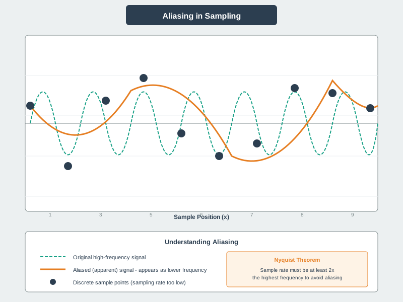
Set the action threshold from the measurement purpose. A room-temperature logger may tolerate slow drift but still reject mains hum aliases; a vibration monitor may preserve higher mechanical frequencies but reject motor-drive sidebands. The sample rate and filter cutoff should follow that purpose, not a generic "twice the sensor update rate" shortcut.
Sample rate
fs > 2 × fmax. Sampling exactly at 2 × fmax is not enough in practice; leave margin.
Nyquist frequency
fs / 2. The ceiling of what the data can represent. Content above it aliases.
Aliasing
An out-of-band tone reappears at a lower frequency and masquerades as real data.
Anti-alias filter
An analog low-pass before the ADC removes energy above fs/2 so it cannot fold in.
A practical overview review ends with a plain sentence that anyone can test: "The product accepts signals up to X Hz, samples at Y Hz, places a cutoff at Z Hz, and rejects known interference before it reaches the converter." That sentence is stronger than a bare Nyquist calculation because it includes the physical source of the data, the analog boundary, and the transition margin. If the team cannot name those four values, the sampling design is not ready for firmware cleanup, dashboard tuning, or field deployment.
When the sentence fails, choose the smallest correction that changes the physics: move the analog cutoff lower, sample faster, reduce the sensor or amplifier bandwidth, shield or reroute the interference source, or change the measurement method. A later dashboard threshold is not a correction, because it only sees the false low-frequency pattern after sampling has already made it look real.
Overview Knowledge Check
Practitioner: Computing Where a Tone Lands
A single tone at frequency fin sampled at fs appears in the data at f_alias = | fin − fs × round(fin / fs) | — that is, it folds into the 0–fs/2 band. Every frequency that is a mirror image around a multiple of fs/2 lands on the same apparent frequency.
Worked example — 50 Hz mains hum. You sample a slow sensor at fs = 80 Hz, so the Nyquist frequency is 40 Hz. Ambient 50 Hz powerline interference is above 40 Hz, so it aliases to |50 − 80| = 30 Hz. Your data now contains a phantom 30 Hz wander that looks exactly like a real 30 Hz signal — and a digital filter cannot tell them apart.
For a design review, calculate aliases for both expected signal content and credible unwanted content. Start with known environmental lines such as 50 or 60 Hz mains, pump or fan blade-pass frequencies, motor PWM sidebands, switching-regulator ripple, and any intentional excitation signal. Then run each one against the selected sample rate and record where it lands. A dangerous alias is not only "above Nyquist"; it is "above Nyquist and landing inside a frequency band the product interprets as meaningful behavior."
| Input tone (fs = 100 Hz, Nyquist = 50 Hz) | Appears in data at |
|---|---|
| 20 Hz (in band) | 20 Hz — captured correctly |
| 80 Hz | |80 − 100| = 20 Hz — aliased |
| 120 Hz | |120 − 100| = 20 Hz — aliased |
| 180 Hz | |180 − 200| = 20 Hz — aliased |
Because 20, 80, 120, and 180 Hz all collapse onto 20 Hz, aliasing is irreversible: the sampled data cannot say which one was really present. The fix must happen before sampling — an analog anti-alias low-pass filter, or a higher sample rate.
Practitioner evidence should pair each alias calculation with an action. If the alias lands outside the decision band, document why it is harmless or still attenuated. If it lands inside the decision band, increase fs, add analog filtering, narrow the front-end bandwidth, change the sensor placement, or prove by sweep testing that the interference level is below the error budget. The reviewer should also check that averaging is not being misused: averaging can reduce random noise, but coherent aliased tones average into a stable false signal.
Practitioner Knowledge Check
Under the Hood: Why a High Sample Rate Alone Is Not Enough
Two things trip up real designs. First, sampling exactly at 2 × fmax is a knife-edge: a sine sampled at precisely twice its frequency can land on its zero crossings every time and reconstruct as nothing. The theorem requires fs > 2 × fmax, so engineers leave headroom — often sampling at 5× to 10× the signal bandwidth.
Second, the anti-alias filter must be analog and physically before the ADC, because once aliasing has happened it is baked into the samples. A real low-pass filter has a finite roll-off, not a brick wall, so it needs a transition band between the signal bandwidth and fs/2 to attenuate out-of-band energy. That is the deeper reason to oversample: raising fs pushes fs/2 further out and gives a simple RC or higher-order filter room to roll off before frequencies can fold. (A separate reconstruction filter after a DAC does the mirror-image job of removing the sampling images on the output.)
The filter contract should state more than a component value. Record the passband that must stay flat enough for measurement, the stopband that must be attenuated enough to protect the ADC, the transition band between them, the expected filter order or roll-off, and the tolerance of the resistor, capacitor, op-amp, or switched-capacitor implementation. A first-order RC filter rolls off slowly, so it may need a much higher sample rate than the ideal Nyquist line suggests.
Under the hood, the ADC input path also has loading and acquisition limits. A large filter resistor can interact with the ADC sample-and-hold capacitor; a weak op-amp can settle too slowly; a multiplexed input can carry charge from the previous channel. Those effects do not change the Nyquist theorem, but they can make the anti-alias filter fail in hardware. The acceptance test should sweep frequency at realistic amplitude, confirm passband gain and phase where they matter, confirm stopband attenuation before fs/2, and repeat at the sample rate, gain, and sensor source impedance used in the actual product.
Under-the-Hood Knowledge Check
Release Checklist
Before signing off a sampling and anti-alias design, verify that:
- The highest meaningful signal frequency is stated, not guessed from the desired reporting interval.
-
The selected sample rate puts
fs / 2safely above the signal bandwidth and leaves transition-band room for a real analog filter. - Known interference sources such as 50/60 Hz mains, motor PWM, radio clocks, and switching supplies are checked for alias frequencies.
- The anti-alias filter is analog and physically before the ADC input.
- Digital filtering and averaging are documented as post-sampling cleanup, not as an alias-prevention substitute.
- Oversampling cost is budgeted in ADC current, CPU time, buffer size, storage, and radio payload volume.
- Reconstruction filtering is reviewed separately for DAC or PWM output paths.
See Also
- Sampling Rate and Aliasing: Return to the main Nyquist chapter for sampling-rate intuition and examples.
- ADC Fundamentals: Connect sample-rate decisions to ADC conversion and resolution limits.
- ADC Architecture and Resolution Contracts: Review oversampling, dither, and architecture trade-offs.
- ADC/DAC Worked Examples: Practice complete conversion calculations.
- Signal Processing Essentials: Relate aliasing and filtering to frequency-domain analysis.
Next
After alias-prevention rules are explicit, continue with DAC and PWM Output to see the output-side mirror of sampling and reconstruction.