12 Choosing Simulation Tools
Choosing the Right Evidence Tool for an IoT Network Decision
12.1 Start With the Evidence You Need
Imagine choosing a simulator because it is familiar, then discovering the real risk was firmware reconnect behavior or RF coverage in a warehouse aisle. Tool choice should start with the evidence question. If the claim depends on packets, code, radio conditions, installed gateways, or operations telemetry, the tool has to match that claim rather than decorate the design.

Phoebe’s Why
Every radio model has to assume some antenna pattern, and the easiest default is isotropic: a mathematical point source that spreads its power identically in every direction. That default is a real physical claim about a real solid-angle footprint – the whole sphere. A real deployed gateway antenna is not isotropic; even a modest sector antenna concentrates the same power into a fraction of that sphere. So an unconfigured simulator does not just get the range wrong, it gets the shape wrong: it predicts a uniform bubble of coverage around a gateway when the real antenna only illuminates a wedge pointed at the dock doors, and predicts near-zero coverage exactly where the real sector antenna is strongest. That is the physical fact underneath this chapter’s own warning that “ns-3 results depend on the configured propagation model” and that “RF surveys depend on antenna orientation.”
The Derivation
Isotropic spreading over a sphere of radius \(d\):
\[S_{iso} = \frac{P_t}{4\pi d^2}\]
A directional antenna of gain \(G\) concentrates the same transmit power into a narrower solid angle, and regulators cap the combination as EIRP:
\[S_{dir} = G\,\frac{P_t}{4\pi d^2}, \qquad \mathrm{EIRP(dBm)} = P_t(\mathrm{dBm}) + G(\mathrm{dBi})\]
Idealizing the pattern as one main lobe, the solid angle it occupies and the fraction of the full sphere (\(4\pi\) sr) that fraction represents are
\[\Omega \approx \frac{4\pi}{G}, \qquad \text{fraction of sphere} = \frac{\Omega}{4\pi} = \frac{1}{G}\]
At a fixed conducted transmit power \(P_t\), the range at which the same received power density is reached scales as \(\sqrt{G}\).
Worked Numbers: The Chapter’s Own “Cover The West Loading Dock” Claim
- Catalog-typical 2.4 GHz ISM ceiling: EIRP \(= 20\) dBm. An isotropic default radiates \(P_t = 20\) dBm \(= 100\) mW across \(\Omega = 4\pi = 12.6\) sr – 100% of the sphere.
- A real 8 dBi sector gateway antenna at the same EIRP ceiling: \(G = 10^{8/10} = 6.31\times\), so conducted power is \(P_t = 20 - 8 = 12\) dBm \(= 15.8\) mW, covering only \(\Omega = 4\pi/6.31 = 1.99\) sr \(\approx 15.8\%\) of the sphere.
- If instead the model keeps conducted power fixed at 100 mW and only forgets to configure the 8 dBi gain – a plausible default-config mistake, not a chapter fact – the in-beam range is under-predicted by \(\sqrt{6.31} = 2.51\times\), while every direction outside that 15.8% wedge is over-predicted, since the real antenna delivers almost nothing there.
- Net effect: the same “gateway pair covers the loading dock” claim can be a 2.51x range error in the dock’s own direction and a near-total coverage error everywhere else, from one unconfigured antenna parameter – which is exactly why the chapter pairs every model output with an RF walk test rather than trusting the simulator’s range number alone.
12.2 Learning Objectives
By the end of this chapter, you will be able to:
- Choose a network simulation or measurement tool based on the design question it must answer.
- Distinguish packet-level simulation, firmware-aware emulation, modular simulation frameworks, packet capture, RF survey, and field telemetry.
- Explain why tool output must be tied to assumptions, scenarios, metrics, and validation evidence.
- Identify when a classroom visual tool is useful for learning but insufficient for production design evidence.
- Prepare a tool-selection record that another reviewer can reproduce or challenge.
12.3 Choose Tools by Question
A network tool is only useful when it observes or models the behavior behind a real design decision. A simulator can compare alternatives before deployment. An emulator can exercise firmware paths. A packet capture can show what actually crossed an interface. An RF survey can reveal site conditions. Operations telemetry can show whether a deployed network stays healthy over time. The mistake to avoid is treating all of those outputs as equivalent. A packet-level model, a Contiki-NG mote run, a Wireshark trace, a LoRaWAN gateway export, and a pilot dashboard answer different questions.
Start with the decision, then choose the least complex tool that can produce credible evidence. A classroom topology visualizer may help a learner understand routing, but it cannot prove LoRaWAN coverage, Wi-Fi roaming, Thread mesh recovery, gateway backhaul resilience, or battery life without additional measurements. A design team should first ask whether the claim depends on modelled packets, real firmware, real RF, installed gateways, application logs, or long-run operations. That question keeps tool choice practical. If the risk is MQTT reconnect behavior after broker failover, a small broker test plus packet capture may beat a large radio simulation. If the risk is RPL repair after a parent disappears, ns-3, OMNeT++/INET, or Cooja may be worth the setup. If the risk is metal shelving blocking coverage, an RF walk test and pilot node logs carry more weight than a diagram.
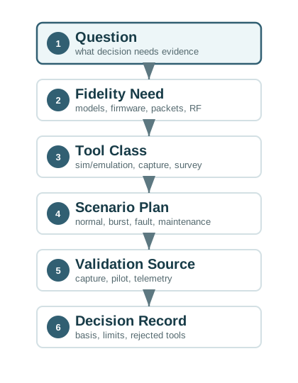
The route also protects reproducibility. Before the tool is run, the team should name the scenario, metric, version, input files, random-seed policy where relevant, capture point, gateway log source, and validation check. After the tool is run, the result should say what it can support and what it cannot support. That boundary is the difference between evidence and decoration.
- Model tools: Useful for repeatable comparisons of topology, routing, traffic, queueing, and protocol behavior.
- Measurement tools: Useful for checking real packets, RF conditions, gateway health, installation effects, and operational drift.
- Review artifacts: Tool version, inputs, scripts, traces, assumptions, model limits, and validation source must travel with the result.
12.4 Match Tool Class to Evidence
Use ns-3 or OMNeT++/INET when the question is about repeatable network behavior such as routing recovery, queue depth, protocol overhead, contention, or scale. Use Cooja with Contiki-NG when constrained-node firmware, mote logs, RPL, 6LoWPAN, or low-power stack behavior matters. Use Wokwi, Renode, or board-level test harnesses when firmware interaction is more important than large-scale radio realism. For a Thread or Zigbee mesh, the practitioner decision may be whether powered-router density and retry limits keep recovery inside the service target. For LoRaWAN, it may be whether spreading-factor distribution, duty-cycle limits, join capacity, and gateway backhaul leave enough margin. For Wi-Fi, Ethernet, LTE-M, NB-IoT, or private cellular, the relevant evidence may shift toward DHCP, DNS, roaming, SIM lifecycle, APN/VPN routing, cloud reachability, and operational ownership.
Use measurement tools when reality is the question. Wireshark or tshark can confirm MQTT, CoAP, TCP, TLS, BLE, or 802.15.4 packet behavior at a capture point. iperf3 can test throughput and jitter on IP links. ChirpStack or The Things Stack gateway logs can expose LoRaWAN joins, RSSI/SNR, frame counters, ADR behavior, and downlink limits. Broker logs, cloud IoT logs, RF survey results, and battery-current traces should be tied back to the model assumption they confirm or challenge. If a simulator predicts acceptable latency but a packet capture shows repeated TLS handshakes after every sleep cycle, the design question changes. If a gateway log shows join failures in one loading bay, the simulation needs a site-specific coverage check. If pilot telemetry shows retries concentrated after firmware update windows, the scenario pack needs maintenance traffic, not only steady-state telemetry.
A useful tool-selection record is short but specific. It names the layer under test, the tool class, the selected product or framework, the scenario, the metric, the validation source, and the rejected alternatives. For example, “use OMNeT++/INET to compare mesh recovery under one-router failure, validate the route-repair timing with a five-node pilot and packet capture, and do not use the result to claim battery life.” That level of precision helps reviewers see whether the tool is strong enough without pretending it proves more than it does.
- Name the layer. Decide whether the claim depends on RF, MAC, routing, transport, application protocol, firmware timing, or operations.
- Pick the evidence class. Choose simulation, emulation, capture, survey, pilot, or telemetry based on that layer.
- Preserve reproducibility. Save versions, inputs, scripts, seeds, traces, topology files, and validation notes before interpreting results.
12.5 Tool Output Validity Boundaries
Every tool has a validity boundary. ns-3 results depend on the configured propagation model, traffic model, random seeds, and protocol modules. OMNeT++/INET results depend on selected components and simplified layers. Cooja exercises Contiki-NG behavior but still abstracts physical deployment. Wireshark shows captured packets, not the packets that were lost before the capture point. RF surveys show a site at a particular time, with particular antennas, mounting, and interference. Operations dashboards show what the deployed platform retained, which may omit rejected packets, local outages, encrypted payload detail, or devices that never joined.
A good tool-selection record states which boundary matters. For LoRaWAN, that may include regional duty-cycle limits, spreading factor, payload size, gateway placement, ADR, and downlink scarcity. For Thread or Zigbee, it may include 802.15.4 channels, route repair, router density, commissioning, and interference. For Wi-Fi, it may include channel width, roaming, airtime, DHCP/DNS behavior, backhaul capacity, and access-point logs. For a cellular design, the record may include modem firmware, carrier profile, APN, NAT behavior, coverage sample, SIM or eSIM lifecycle, power-save mode, and roaming assumptions. For an application-protocol claim, it may include MQTT session expiry, QoS, retained messages, keepalive, CoAP confirmable retransmission, TCP reconnect timing, TLS resumption, and broker throttling.
The hidden mechanism is usually timing and loss. Simulators generate events from configured distributions; packet captures depend on timestamp accuracy and capture placement; RF surveys depend on antenna orientation and environmental state; gateway dashboards depend on aggregation windows; and pilots depend on who installed, provisioned, powered, and maintained the devices. A result that looks authoritative can still be wrong for the decision if one of those mechanisms is outside the tool. That is why the validation step should attack the riskiest assumption first. Compare a modelled delivery ratio with gateway counters, compare a simulated retry burst with packet traces, compare an RF prediction with measured RSSI/SNR, and compare firmware sleep-state assumptions with current traces or device logs.
- Input boundary: Topology, traffic distribution, radio model, firmware path, queue policy, sampling interval, and outage scenario.
- Observation boundary: Capture point, clock sync, antenna, channel, test duration, pilot size, and log-retention window.
- Decision boundary: The exact design choice the tool can support and the residual risk that still needs field validation.
12.6 Prerequisites
This chapter assumes you have already reviewed:
- Network Design Fundamentals: requirements, topology, gateway placement, and acceptance criteria.
- Network Design Methodology: decisions, assumptions, scenarios, evidence plans, and validation.
- Network Design Introduction: the overall evidence route from requirements to validation.
12.7 What This Chapter Does
This is a tool-selection chapter, not a simulator tutorial. It helps you decide which type of evidence tool belongs in a network design workflow and what limits to write down before trusting the output.
Packet-level simulation
Use when routing, contention, queueing, protocol behavior, scale, or scenario sweeps are the main uncertainty.
Firmware-aware emulation
Use when the embedded stack, radio driver behavior, logs, or application firmware must be tested close to device code.
Capture and survey tools
Use packet captures, gateway logs, spectrum checks, and site surveys to test whether assumptions match a real environment.
Field telemetry
Use production and pilot metrics to catch drift, weak links, outage recovery, commissioning issues, and maintenance problems.
12.8 Tool Selection Route
Use the route introduced in the Overview before opening a simulator. It prevents the common failure mode where the team spends time configuring a tool that cannot answer the actual design question.
12.9 Match Tool to Network Claim
A network-design tool is credible only when its observation boundary matches the claim under review.
- Classify the claim. Decide whether the claim is about RF coverage, 802.15.4 mesh recovery, LoRaWAN gateway capacity, Wi-Fi roaming, MQTT retry behavior, firmware timing, or operations health.
- Choose the evidence class. Use ns-3 or OMNeT++/INET for repeatable packet behavior, Cooja for Contiki-NG and RPL/6LoWPAN code paths, Wireshark or tshark for captured packet behavior, iperf3 for IP throughput and jitter, and gateway or broker logs for deployed service behavior.
- Define the scenario before running the tool. Name topology, traffic load, payload size, retry policy, outage, interference, firmware version, antenna placement, gateway position, and the metric that will change the decision.
- Check one important assumption against reality. Pair the model with a packet capture, RF survey, pilot log, gateway-health export, or field measurement before using the output as design evidence.
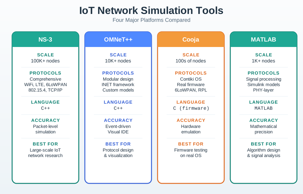
12.10 Evidence Tool Classes
12.11 Incremental Examples
Beginner Example: A classroom team compares MQTT and CoAP message overhead for a small sensor payload. Wireshark or tshark on a local broker path can show TCP, TLS, MQTT CONNECT/PUBLISH/PUBACK, CoAP confirmable messages, retransmissions, and payload size. This is enough to learn protocol behavior, but it does not prove warehouse RF coverage or battery life.
Intermediate Example: A design team studies whether Thread or Zigbee route repair stays inside the required recovery window after one router fails. OMNeT++/INET or an ns-3 study can model topology and traffic, while a small physical 802.15.4 pilot checks channel interference, commissioning state, neighbor quality, and gateway logs.
Advanced Example: A city sensor deployment compares LoRaWAN gateway placement and downlink pressure. The team may combine a propagation estimate, The Things Stack or ChirpStack gateway metadata, RSSI/SNR samples, frame counters, spreading factors, ADR behavior, regional duty-cycle limits, and a pilot route. The tool stack is stronger because it combines model output with gateway and site evidence.
12.12 Tool Profiles
12.12.1 ns-3
Use ns-3 when the evidence depends on packet-level behavior, wireless models, routing choices, traffic patterns, queueing, repeated runs, or scenario sweeps. It is a strong fit for research-style studies and design comparisons where scripts, traces, and configuration files can be reviewed.
Write down:
- ns-3 version and modules used.
- Scenario files, topology inputs, random-seed policy, and trace-processing scripts.
- Radio, propagation, MAC, routing, traffic, queueing, and energy assumptions.
- Which field measurement or published model supports the assumptions.
12.12.2 OMNeT++ and INET
Use OMNeT++ with INET when modular composition, reusable protocol components, event inspection, visual debugging, and structured result recording are important. It is useful when the study benefits from a component framework rather than a single-purpose script.
Write down:
- Framework versions, model packages, and custom modules.
- NED topology, ini configuration, traffic sources, and result filters.
- Protocol layers modeled and protocol layers simplified.
- How the model was checked against expected packet flow.
12.12.3 Cooja and Contiki-NG
Use Cooja when the question depends on Contiki-NG firmware behavior, mote logs, RPL/6LoWPAN behavior, radio duty cycling, embedded timing, or application code paths. It is especially useful when simulated nodes run code close to the code intended for constrained devices.
Write down:
- Contiki-NG version, mote type, firmware commit, and radio medium.
- Mote placement, traffic pattern, serial logs, and packet capture settings.
- Which behavior is emulated and which environment details are still abstract.
- What physical testbed or pilot will validate the radio and power assumptions.
12.12.4 Wireshark and Packet Captures
Use packet capture when the question is “what actually happened on the wire or over the air?” Captures are not a simulator, but they are often the evidence that proves a simulator or emulator is modeling the right behavior.
Write down:
- Capture point, channel, interface, filter, timestamp basis, and anonymization choices.
- Protocol decode limits and whether encrypted payloads are expected.
- How packets are matched to application events, gateway logs, or simulator traces.
- Which design claim the capture confirms or refutes.
12.12.5 Field Survey and Operations Tools
Use RF survey, gateway dashboards, device health logs, and monitoring systems when the design question depends on the real site or long-run operation. These tools expose problems that a simulator rarely knows about: blocked antenna paths, changing interference, power failures, commissioning mistakes, and support workflow gaps.
Write down:
- Site, time window, equipment, firmware, antenna configuration, and data-retention limits.
- Metrics collected and missing metrics.
- Known blind spots such as inaccessible rooms, encrypted traffic, or incomplete gateway logs.
- Follow-up action when field behavior disagrees with the model.
12.13 Simulation, Emulation, and Measurement
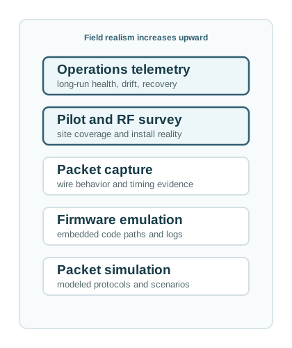
The strongest workflow often combines more than one tool. A simulator explores alternatives. An emulator checks firmware behavior. A packet capture explains protocol behavior. A field survey or pilot checks the site. Operations telemetry shows whether the deployment keeps working.
Practical rule: trust a tool only for the layer it actually observes or models. A packet simulator does not prove antenna placement. A packet capture does not test unbuilt scale. A classroom topology tool does not validate low-power wireless behavior. A field dashboard does not explain all protocol causes without traces.
12.14 Selection Questions
Use these questions before choosing a tool:
Which layer matters?
Physical/RF, MAC, routing, transport, application traffic, firmware timing, gateway backhaul, or operations process.
What must be real?
Packet timing, firmware, radio model, application workload, site geometry, antenna placement, or support workflow.
Can another reviewer rerun it?
Version, configuration, inputs, seed policy, trace paths, scripts, and output summaries must be available.
What will check reality?
Capture, RF survey, gateway telemetry, pilot logs, physical testbed, or production monitoring.
12.15 Try It Now
Pick one network claim and choose the first tool you would use. Write the claim as one sentence, then name the tool, the metric, the scenario, and the reality check. For example: “A LoRaWAN gateway pair can cover the west loading dock with reliable uplinks.” First tool: gateway metadata plus an RF walk test. Metric: uplink delivery, RSSI/SNR, spreading factor, and join success. Scenario: dock doors open and closed. Reality check: pilot node logs from the final mounting height.
12.16 Micro-Exercise: Reject the Wrong Tool
A team wants to prove that BLE commissioning survives Android background-permission changes, but proposes only an ns-3 packet simulation. Reject that tool choice for the first pass. The claim depends on phone OS permission flow, BLE scanning/connection behavior, app state, pairing recovery, and user interaction. A phone-based test harness with Android logs, BLE sniffer capture where possible, and app telemetry is a better starting point.
12.17 Tool-Selection Records
A tool-selection record is a short artifact that prevents tool choice from becoming folklore.
12.18 Warehouse Protocol Comparison
A team must choose an IoT network approach for a warehouse with mobile equipment, shelves, periodic telemetry, and alarm traffic.
12.19 Practice Checks
12.20 Common Pitfalls
A familiar tool is not automatically the right tool. Start with the decision and the evidence needed to support it.
Visual topology tools can help teach switching, routing, and basic IoT ideas. They usually do not validate low-power wireless propagation, firmware timing, radio duty cycling, or field operations.
Every tool simplifies something. Record which layers, radios, traffic classes, firmware behavior, and operations details are outside the model.
Simulation and emulation are predictions. Important claims need checks against captures, surveys, pilot logs, hardware tests, or operations telemetry.
12.21 Summary
- Tool choice should follow the design question, not personal familiarity or tool popularity.
- Packet-level simulators, modular frameworks, firmware-aware emulators, packet captures, RF surveys, pilots, and operations telemetry answer different questions.
- Strong tool evidence includes versions, inputs, assumptions, scenarios, scripts, traces, and validation status.
- A tool-selection record documents chosen tools, rejected alternatives, model limits, and residual risk.
- Simulation becomes stronger when paired with measured evidence that challenges the assumptions.
12.22 See Also
- Network Design Fundamentals defines the requirements and acceptance criteria that tool output should support.
- Network Design Methodology shows how assumptions, scenarios, and validation sources fit into the broader design process.
- Network Simulation Methodology explains how to run the simulation study after the tool class is chosen.
- Network Traffic Analysis covers packet-capture interpretation when measured traffic must confirm or challenge a model.
12.23 References
- ns-3 Project. Documentation.
- OMNeT++ Project. Simulation Manual.
- INET Framework. User’s Guide.
- Contiki-NG Project. Running Contiki-NG in Cooja.
- Wireshark, User’s Guide, for packet-capture evidence and troubleshooting workflows.
12.24 What’s Next
The next chapter, Network Simulation Methodology, shows how to run a simulation study after the evidence tool has been chosen.
| Previous | Current | Next |
|---|---|---|
| Network Design Methodology | Network Simulation Tools | Network Simulation Methodology |
12.25 Key Takeaway
Simulation tools differ in fidelity and purpose. Choose tools that match the question being asked, whether it is packet behavior, radio coverage, energy use, topology scaling, or protocol comparison.