Begin with a control decision and ask how fast it must be made and who is allowed to make it. ISA-95 and real-time design tell the story of boundaries: field control, supervisory visibility, production execution, and business planning each operate on different timing promises.
Phoebe’s Field Notes: Sizing the Anti-Alias Filter for a 1 kHz Motor Loop
Phoebe’s Why
Every analog value entering a PLC survives two separate physics problems before it becomes a trustworthy number. First, Ohm’s law: a 4-20 mA current loop is deliberately current-based so cable resistance cannot corrupt the signal, but the ADC still needs a voltage, so a precision resistor converts current to voltage right at the input – \(V=IR\), nothing more exotic than that. Second, Nyquist: once that voltage is sampled at a fixed rate, any vibration or electrical noise energy above half the sample rate does not disappear, it folds back down and masquerades as a real low-frequency signal. An RC low-pass filter sitting between the shunt resistor and the ADC is the circuit that stops that folding, and its cutoff has to be chosen with the sampling rate in mind, not sized on its own.
The Derivation
Current-loop-to-voltage conversion, Ohm’s law:
\[V = I R_{\mathrm{shunt}}\]
RC low-pass time constant and cutoff frequency:
\[\tau = RC, \qquad f_c = \frac{1}{2\pi RC}\]
Anti-alias constraint tying the filter to the sampler:
\[f_c \ll \frac{f_s}{2}\]
Quantization step and SNR for the resulting digitized value, \(N\)-bit ADC over span \(V_{\mathrm{span}}\):
4-20 mA loop into a 250 \(\Omega\) precision shunt (catalog-typical): \(V = IR\) gives \(1.00\) V at 4 mA and \(5.00\) V at 20 mA, a \(4.00\) V span for the ADC
This chapter’s own sampling rate: 1 ms period \(\to f_s = 1000\) Hz \(\to\) Nyquist limit \(f_{\max} = 500\) Hz
Anti-alias cutoff, chosen safely below that limit:\(f_c = 400\) Hz, with a standard \(R = 1.00\) k\(\Omega\): \(C = 1/(2\pi Rf_c) = 1/(2\pi \times1000\times400) = 398\) nF (nearest standard film capacitor)
Quantization tie, 12-bit ADC over the 4.00 V span (catalog-typical PLC analog input): \(q = 4.00/4096 = 0.977\) mV; \(\mathrm{SNR} = 6.02(12)+1.76 = 74.0\) dB – the shunt resistor, the anti-alias filter, and the ADC resolution form one signal chain, each stage sized against the same 1 kHz sampling decision
Chapter Roadmap
This chapter moves through the factory timing stack in five stops:
First separate ISA-95 levels by deadline, owner, and failure consequence.
Then classify each function as hard real-time, soft real-time, or best effort.
Next map protocols and platforms to the level where their timing behavior belongs.
After that test the rules on the assembly-line case and bandwidth calculator.
Finally use the quizzes and pitfalls to check that no upper layer has quietly become the control owner.
Checkpoints recap the main design moves, and collapsed callouts are optional refreshers or deeper worked examples.
44.2 Learning Objectives
After completing this chapter, you will be able to:
Differentiate between ISA-95 automation levels and their timing constraints
Distinguish hard real-time from soft real-time requirements and their engineering implications
Design real-time industrial control systems with appropriate latency requirements
Map technologies to appropriate automation levels
Apply the ISA-95 model to industrial IoT architectures
44.3 Prerequisites
Before diving into this chapter, you should be familiar with:
ISA-95, published as IEC 62264, is useful because it prevents one architecture from treating every factory message as the same kind of message. A servo drive, PLC task, HMI alarm, MES work order, and ERP purchase plan all matter, but they live on different time scales and carry different consequences when they arrive late.
The lower levels are close to the physical process. Level 0 devices sense or actuate. Level 1 controllers run machine logic. Level 2 systems supervise and visualize. Level 3 systems coordinate production operations. Level 4 systems plan the enterprise. IoT designs fail when they move Level 0 or Level 1 control decisions into cloud services, dashboards, or business systems that were never built for deterministic deadlines.
The useful pattern is to separate control authority from information visibility. A cloud dashboard may show a motor-current trend, but it should not close a 1 ms torque loop. MES may issue a production order, but it should not bypass a PLC interlock. ERP may plan inventory, but it should not decide whether a robot can enter a safety zone. Each level can exchange data with the others, but the deadline and safety owner must stay attached to the function.
That separation also keeps industrial IoT projects honest. A machine event may need a local trip, a SCADA alarm, a historian sample, an MES quality hold, and an ERP maintenance cost update. Those are related records, not one identical message. The lower levels need deterministic response and fail-safe behavior; the upper levels need context, timestamps, ordering, reconciliation, and business meaning.
Hard real-time: Missing the deadline is a system failure, even if the answer eventually arrives.
Soft real-time: Delay degrades usefulness, but the system can usually continue safely.
Best effort: Correctness depends more on completeness, ordering, and reconciliation than on millisecond delivery.
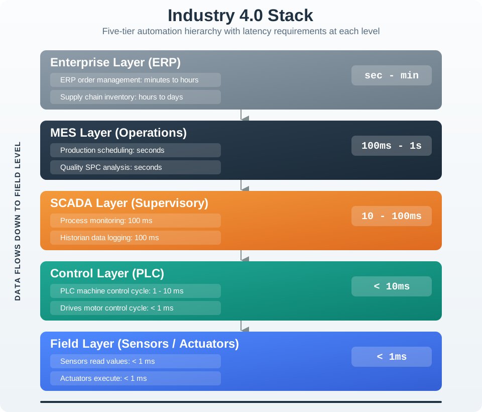
Industry 4.0 stack showing field, control, SCADA, MES, and enterprise layers with progressively slower timing requirements.
Figure 44.1: Timing boundary: each layer has a different owner, deadline, failure mode, and acceptable integration technology.
44.5 Put Decisions at the Lowest Level
A practical ISA-95 design starts with the fastest unsafe or economically damaging event. Emergency stop, light curtain, torque limit, burner management, and motion synchronization belong near certified safety controllers, drives, PLCs, or dedicated real-time hardware. A dashboard can display their state, but it should not be the path that makes them safe.
As timing relaxes, the architecture can move upward. SCADA and HMI systems can supervise lines and alarms. Historians can sample process values for trends. MES can handle work orders, batch phases, genealogy, quality checks, and OEE. ERP can plan demand, inventory, purchasing, and finance. Edge gateways and OPC UA servers often bridge the lower levels to these higher consumers without collapsing the timing boundaries.
For each function, write a timing row before selecting protocols. A packaging line may need a 4 ms registration correction, a 50 ms reject confirmation, a 500 ms HMI alarm update, a 5 second quality-hold decision, and a nightly ERP production reconciliation. These numbers point to different owners and paths. Putting them in one table exposes whether a proposed MQTT, REST, OPC UA, PROFINET, EtherCAT, or database path is being used at the right ISA-95 level.
Use gateways as translators, not as hidden control owners. An OPC UA server can expose PLC tags with semantic names and quality codes; a historian can compress and retain process values; an MES connector can attach work-order, batch, operator, and material context. None of those bridges should silently become the only place where a local stop, interlock, or critical fallback is decided.
Write the deadline. Capture cycle time, maximum latency, jitter tolerance, timeout behavior, and safe fallback for each function.
Name the owner. Decide whether the function is owned by a sensor/actuator, drive, PLC, safety controller, SCADA, MES, historian, gateway, cloud service, or ERP.
Choose the path. Use deterministic paths such as PLC scan cycles, EtherCAT distributed clocks, PROFINET IRT, or CIP Sync where deadlines demand them; use OPC UA, MQTT, REST, or database interfaces only where timing allows.
Define stale-data behavior. Specify when a value becomes stale, who may act on it, and which local action wins if the network or cloud link is unavailable.
44.6 Deadlines Beyond Network Speed
A real-time guarantee includes sensing delay, input filtering, PLC scan time, task priority, network scheduling, controller execution, output update, actuator response, and mechanical settling. A fast Ethernet link does not fix a slow scan cycle, overloaded gateway, nondeterministic task scheduler, or cloud round trip. That is why control engineers measure end-to-end response, not just bandwidth.
Clocking and scheduling matter. Motion systems may use EtherCAT distributed clocks, PROFINET IRT time slots, CIP Sync with IEEE 1588 PTP, or TSN mechanisms such as IEEE 802.1AS time synchronization and 802.1Qbv time-aware shaping. Safety functions may rely on certified PLCs, safety relays, safety-rated drives, PROFIsafe, CIP Safety, or IEC 61508/IEC 61511 engineering practices rather than ordinary application code.
Higher levels have their own correctness rules. MES transactions need sequence, genealogy, batch state, operator action, and quality disposition. Historians need timestamp source, compression, exception/deviation rules, and data quality. ERP integrations need reconciliation and retry. These concerns are different from sub-millisecond determinism, but they are still part of a reliable industrial IoT architecture.
Determinism is normally engineered by bounding every queue and scheduler in the path. A PLC task with a fixed scan period, a drive with synchronized clocks, a switched industrial Ethernet segment with reserved time slots, and a local fail-safe output can be analyzed for worst-case behavior. A Wi-Fi channel, TCP retransmission, broker queue, cloud function, or shared database can still be valuable, but it belongs on a telemetry or coordination path where late data degrades usefulness instead of breaking the machine.
When data crosses levels, preserve both time and authority. A value should carry timestamp source, quality code, equipment mode, work-order or batch context, and source system so that SCADA, historian, MES, and ERP consumers do not mistake an old value for a live control signal. This is why ISA-95 integration is not only a network diagram; it is a contract between real-time behavior, operational semantics, and business records.
Measure latency budget: Include sensor, controller, network, compute, output, and mechanical response.
Separate authority: Keep certified control and safety functions local; let upper layers request, supervise, or record unless engineered for direct control.
Preserve context: Carry timestamp, quality code, equipment state, recipe or work-order context, and source system with data that crosses ISA-95 levels.
44.7 Introduction
Industrial systems have strict timing requirements that vary by automation level. A motor control loop that misses its 1ms deadline can cause equipment damage, while an enterprise report delivered a few seconds late has no operational impact. Understanding these timing requirements is fundamental to designing effective industrial IoT systems.
Real-Time and ISA-95 Basics
Core Concept: The ISA-95 standard defines a five-level automation pyramid that maps industrial systems from field devices (sub-millisecond response) up to enterprise planning (hours-to-days). Each level has distinct timing requirements, and choosing the wrong technology for a given level can cause equipment damage, safety incidents, or wasted resources.
Why It Matters: A missed deadline in a servo, safety, or interlock path can damage equipment, create a safety hazard, or interrupt production. Conversely, using hard real-time hardware for enterprise reporting wastes budget. ISA-95 gives engineers a systematic framework for matching timing requirements to technology choices, keeping safety-critical functions on bounded local paths while business functions use ordinary IT infrastructure.
Key Takeaway: Always design from the bottom up – identify the hardest real-time constraint first (usually Level 0-1 safety or motion control), select deterministic protocols and RTOS platforms for those functions, then relax requirements as you move up the pyramid toward enterprise integration. Never attempt to use cloud or IT technologies for hard real-time control.
Factory Speed Limits
Hey there, young engineer! Sammy the Sensor has discovered that factories have speed limits – just like roads!
The Factory Speed Pyramid: Imagine a factory is like a tall building with 5 floors:
Basement (Level 0): This is where the actual machines live – robot arms, conveyor belts, temperature sensors. They need to react SUPER fast – like catching a ball that is thrown at you! (Less than 1 millisecond – that is 1/1000th of a second!)
Floor 1 (Level 1): The “brain boxes” (PLCs) that tell machines what to do. They need to be fast too – like a goalkeeper saving a penalty! (1-10 milliseconds)
Floor 2 (Level 2): The big screens where humans watch everything happening. Humans are slower than machines, so updates every second are fine – like checking the scoreboard during a game!
Floor 3 (Level 3): The factory managers planning what to make next. They work in minutes and hours – like a coach planning the next play.
Floor 4 (Level 4): The big bosses deciding what products to build next month. They work in days and weeks – like planning what sport to play next season!
Why Speed Matters: Imagine if the brain box (PLC) told a robot arm to STOP, but the message took 5 whole seconds to arrive. The robot would have already crashed into something! That is why faster floors need special “express delivery” networks, while the upper floors can use regular internet – just like how an ambulance needs a siren to go fast, but a mail truck can take the regular road.
Sensor Squad Memory Trick:
Level 0-1 = Lightning fast (machines talking to machines)
Level 2 = Human speed (people watching screens)
Level 3-4 = Planning speed (thinking and deciding)
Hard real-time = MUST arrive on time, or something breaks!
Soft real-time = Should be fast, but a tiny delay is OK
44.8 ISA-95 Automation Pyramid
Time: ~10 min | Difficulty: Intermediate | Unit: P03.C06.U05
The first pass above named the boundary problem. Now we turn that boundary into the standard five-level pyramid used to place real factory systems.
Key Concepts
ISA-95 Level 0: Physical process layer containing sensors, actuators, drives, valves, and the machine state they measure or change.
ISA-95 Level 1: Basic control layer where PLCs, PACs, DCS controllers, safety controllers, and drives execute local control logic.
ISA-95 Level 2: Supervisory layer containing SCADA, HMI, alarms, recipes, and historians used by operators and engineers.
ISA-95 Level 3: Operations-management layer where MES, batch, genealogy, OEE, quality, and production-dispatch systems coordinate work.
ISA-95 Level 4: Enterprise-planning layer where ERP, finance, procurement, demand planning, and supply-chain systems make business decisions.
Hard Real-Time: A deadline class where a late result is a failure, not merely an inconvenience.
Jitter: Variation in timing from cycle to cycle; for synchronized motion, bounded jitter can matter more than average latency.
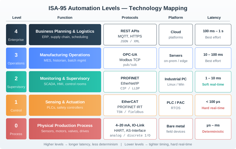
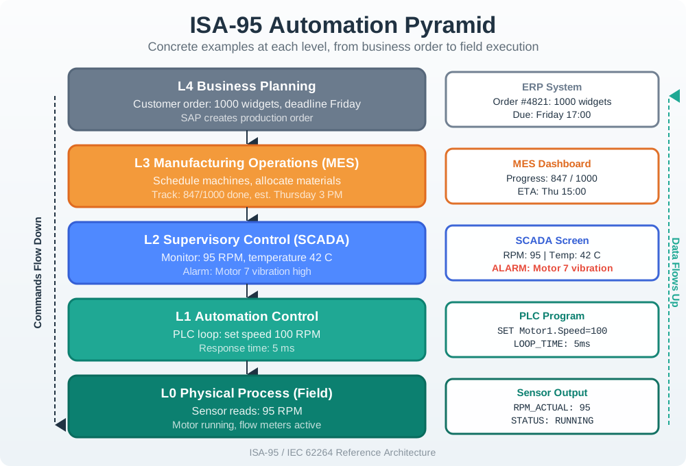
The ISA-95 standard (also known as IEC 62264) defines the interface between enterprise and control systems:
ISA-95 Automation Pyramid
Figure 44.2: ISA-95 separates physical process, control, supervisory, operations, and business-planning responsibilities so timing and authority are not collapsed into one path.
44.9 Timing Requirements by Level
44.9.1 Level 0: Field Devices (Sub-millisecond)
The physical interface with the manufacturing process:
Examples: Daily production planning, weekly demand forecasting, monthly financial closing
Characteristics:
Business process integration
Long-term planning horizons
Financial and customer data
Corporate-wide visibility
Checkpoint: Timing Ladder
You now know:
Level 0 field devices can operate below 1ms, while Level 1 control commonly sits in the 1-10ms range.
Level 2 supervision moves at 100ms-1s, Level 3 operations moves in seconds to minutes, and Level 4 enterprise work moves in hours-days.
A single machine event can create a local trip, SCADA alarm, historian sample, MES quality hold, and ERP cost update without giving each record the same deadline.
Try it: Adjust the system type and number of devices to see how timing requirements and bandwidth change across ISA-95 levels. Notice how motion control requires orders of magnitude faster response times than enterprise planning.
44.11 Determinism vs. Throughput
With the level timing ladder in place, the next question is what kind of promise each deadline needs. Some deadlines are hard failures; others are quality-of-service targets.
Industrial systems distinguish between different real-time guarantees:
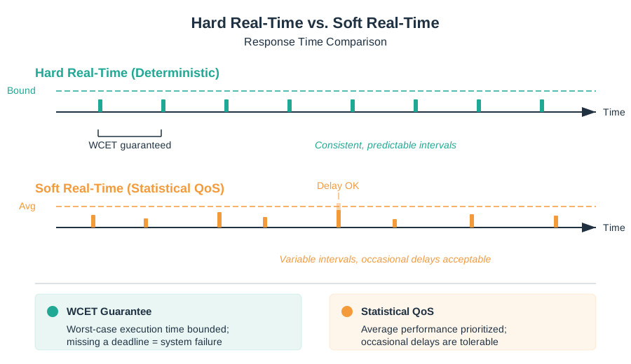
Hard real-time versus soft real-time timing
Figure 44.3: Hard real-time paths are engineered around bounded worst-case behavior; soft real-time paths are judged by usefulness under expected delay and jitter.
Hard vs Soft Real-Time Summary
Hard real-time: Response time is bounded and predictable. Missing a deadline is a system failure.
Soft real-time: Response time varies, and occasional delays degrade quality but do not stop the system.
WCET guarantee: Hard real-time systems must prove worst-case execution time stays within the deadline.
Statistical QoS: Soft real-time systems optimize average performance and tolerate some jitter.
44.11.1 Hard Real-Time (Deterministic)
Definition: Must respond within guaranteed time; missing deadline is system failure.
Characteristics:
Worst-case execution time (WCET) must be bounded
Jitter must be minimal (<1μs for synchronized motion)
Definition: Should respond quickly but occasional delays acceptable; results in degraded performance, not failure.
Characteristics:
Average response time matters more than worst-case
Some deadline misses tolerable
Standard operating systems acceptable
Statistical quality of service
Examples:
HMI updates
Data logging
Trend analysis
Operator notifications
44.11.3 Best Effort
Definition: No timing guarantees; response when resources available.
Examples:
Historical data analysis
Business reporting
Email notifications
Non-critical analytics
Checkpoint: Deadline Classes
You now know:
Hard real-time means a missed deadline is a failure, which is why safety systems and coordinated motion need bounded worst-case execution time.
Soft real-time fits HMI updates, data logging, trend analysis, and operator notifications where delay degrades usefulness.
Best-effort paths belong to historical analysis, business reporting, email notifications, and other work where completeness matters more than millisecond delivery.
44.12 Jitter and Synchronization
For coordinated motion and distributed control, jitter (timing variation) is often more critical than absolute latency:
Jitter requirements by application:
Application
Cycle Time
Max Jitter
Nodes
Simple I/O
10ms
1ms
10-100
Process control
100ms
10ms
100-1000
Packaging machinery
1ms
100μs
10-50
Printing press
125μs
1μs
20-100
Semiconductor handling
62.5μs
100ns
10-30
Simple I/O: 10ms cycle time, 1ms max jitter, 10-100 nodes
Process control: 100ms cycle time, 10ms max jitter, 100-1000 nodes
Packaging machinery: 1ms cycle time, 100μs max jitter, 10-50 nodes
Printing press: 125μs cycle time, 1μs max jitter, 20-100 nodes
Semiconductor handling: 62.5μs cycle time, 100ns max jitter, 10-30 nodes
Synchronization mechanisms:
IEEE 1588 (PTP): Precision Time Protocol for sub-microsecond sync
GPS timing: Absolute time reference for wide-area systems
The chapter now has two timing ideas on the table: response time and consistency. The jitter calculator isolates the second one so you can see why a smaller average delay is not enough for synchronized axes.
Try it: Adjust the actual jitter value to see how different applications tolerate timing variation. Notice that printing presses and semiconductor handling require sub-microsecond precision, while simple I/O can tolerate milliseconds of jitter.
Knowledge Check: Real-Time Requirements
Question 1: A printing press requires a cycle time of 125 microseconds with maximum jitter of 1 microsecond. Which type of real-time guarantee does this require?
Best effort
Soft real-time
Hard real-time
Near real-time
Answer
c) Hard real-time – A printing press with a 125 microsecond cycle time and 1 microsecond maximum jitter tolerance is a classic hard real-time application. Missing a deadline would cause visible print defects (color misregistration, smearing). Hard real-time requires guaranteed worst-case execution time (WCET) and minimal jitter, typically implemented with specialized hardware like EtherCAT with distributed clocks.
Question 2: At which ISA-95 level would you place a SCADA system that displays alarm conditions to plant operators?
Level 0 – Field Devices
Level 1 – Basic Control
Level 2 – Supervisory
Level 3 – Operations
Answer
c) Level 2 – Supervisory – SCADA (Supervisory Control and Data Acquisition) systems operate at ISA-95 Level 2, which handles monitoring and supervision of production processes. Level 2 includes HMI displays, alarm management, historical data logging, and recipe management. The timing requirement is soft real-time (100ms-1s), which is appropriate for human-operator interfaces.
Question 3: Why is jitter often more critical than absolute latency for synchronized motion control?
Jitter is easier to measure than latency
Coordinated axes need to arrive at positions at exactly the same time, so timing consistency matters more than speed
Jitter only affects wireless networks
Lower jitter always means lower latency
Answer
b) Coordinated axes need to arrive at positions at exactly the same time, so timing consistency matters more than speed – In a multi-axis robot, all servo motors must receive their position commands at precisely the same instant. If one axis is consistently 5ms late but all axes have the same 5ms delay, the motion is perfectly coordinated. But if one axis varies randomly between 1ms and 9ms (high jitter), the axes become unsynchronized, causing mechanical stress, poor surface finish, or collisions.
44.14 Technology Mapping
The following diagram shows how protocols, platforms, and network architectures align with ISA-95 levels:
ISA-95 technology mapping by level
Figure 44.4: Technology choices should follow the level’s deadline, authority, and failure consequence rather than a single preferred protocol.
Technology Mapping Summary
Level 0-1: EtherCAT or PROFINET IRT on PLCs/RTOS for sub-millisecond hard real-time control
Level 2: PROFINET or EtherNet/IP on industrial PCs for supervisory monitoring and HMI workloads
Level 3: OPC-UA or Modbus TCP on servers for MES, historians, and batch coordination
Level 4: REST APIs or MQTT on cloud and enterprise platforms for planning and analytics
44.14.1 Protocol Selection by Level
Level
Typical Protocols
Latency
Determinism
0-1
EtherCAT, PROFINET IRT
<100μs
Hard real-time
1-2
PROFINET, EtherNet/IP
1-10ms
Soft real-time
2-3
OPC-UA, Modbus TCP
10-100ms
Best effort
3-4
REST APIs, MQTT
100ms-1s
Best effort
Level 0-1: EtherCAT or PROFINET IRT, <100μs latency, hard real-time
Level 1-2: PROFINET or EtherNet/IP, 1-10ms latency, soft real-time
Level 2-3: OPC-UA or Modbus TCP, 10-100ms latency, best effort
Level 3-4: REST APIs or MQTT, 100ms-1s latency, best effort
44.14.2 Computing Platform by Level
Level
Platform
OS
Processing
0-1
PLC, PAC, IPC
RTOS, bare metal
Deterministic scan cycle
2
Industrial PC
Windows, Linux
Standard scheduling
3
Server
Windows Server, Linux
Virtualization OK
4
Cloud/Enterprise
Any
Containerization, serverless
Level 0-1: PLC, PAC, or IPC running RTOS or bare metal for deterministic scan cycles
Level 2: Industrial PC running Windows or Linux for standard supervisory scheduling
Level 3: Server hardware running Windows Server or Linux with virtualization
Level 4: Cloud or enterprise platforms using containerized or serverless workloads
44.14.3 Network Architecture by Level
Level
Network
Redundancy
Segmentation
0-1
Dedicated industrial
Ring, dual-port
Air-gapped from IT
2
Industrial Ethernet
RSTP, PRP/HSR
VLAN separated
3
Converged IT/OT
Standard HA
DMZ between zones
4
Corporate/cloud
Internet standards
Firewall protected
Level 0-1: Dedicated industrial networks with ring or dual-port redundancy and air gaps from IT
Level 2: Industrial Ethernet with RSTP or PRP/HSR and VLAN separation
Level 3: Converged IT/OT networks with standard high availability and DMZ zoning
Level 4: Corporate or cloud networks using internet standards and firewall protection
Checkpoint: Technology Placement
You now know:
Level 0-1 control can need EtherCAT or PROFINET IRT below 100μs, while Level 1-2 traffic can often use PROFINET or EtherNet/IP in the 1-10ms range.
OPC-UA fits the Level 2-3 boundary because MES and historian consumers need semantic context, not drive-cycle ownership.
REST APIs and MQTT belong at Level 3-4 integration when the path is planning, analytics, or dashboards rather than machine control.
Try it: Adjust the response time requirement and safety criticality to see how the recommended ISA-95 level changes. The tool applies the decision framework to match your requirements to the appropriate automation level.
Knowledge Check: Technology Mapping
Question 4: An engineer needs to connect 100 PLCs to a Manufacturing Execution System (MES) for production scheduling. Which protocol and ISA-95 level boundary does this cross?
EtherCAT at Level 0-1 boundary
OPC-UA at Level 2-3 boundary
PROFINET IRT at Level 1-2 boundary
MQTT at Level 3-4 boundary
Answer
b) OPC-UA at Level 2-3 boundary – Connecting PLCs (Level 1-2) to an MES (Level 3) crosses the Level 2-3 boundary, which is exactly where OPC-UA excels. OPC-UA provides the semantic data modeling needed for MES integration (production orders, quality data, genealogy), built-in security for the IT/OT boundary, and platform-independent communication.
Question 5: A factory floor network uses air-gapped segmentation. Which ISA-95 level does this practice primarily protect?
Level 4 – Enterprise systems need air gaps from the internet
Level 0-1 – Critical control networks must be physically isolated from IT networks
Level 3 – MES systems require air gaps from SCADA
All levels equally use air-gapped segmentation
Answer
b) Level 0-1 – Critical control networks must be physically isolated from IT networks – Air-gapped segmentation is primarily used at Level 0-1, where dedicated industrial networks (EtherCAT, PROFINET IRT) carry safety-critical and hard real-time control traffic. These networks must be physically isolated from IT networks to prevent cyberattacks from reaching PLCs, safety controllers, and field devices. A compromised Level 0-1 network could cause physical damage, equipment destruction, or endanger human life.
44.16 Assembly Line Design Case
The next scenario puts the timing rules into one design record. Treat each subsystem as a separate row before choosing a protocol.
You are designing the control system for an automotive assembly line with:
100 robotic arms: Each with 6 axes (600 servo motors total)
1,000 quality inspection sensors: Vision systems, force sensors, laser scanners
50 AGVs: Automated guided vehicles delivering parts
10 operator stations: HMIs for monitoring and manual intervention
Requirements:
All robots must be synchronized within 1ms
Quality data must be logged for 10-year traceability
AGVs must avoid collisions with <100ms response time
Operators need real-time production status
Enterprise ERP system needs hourly production counts
Predictive maintenance for all critical assets
44.16.1 Solution: Latency Requirements
Robotic motion control: <1ms hard real-time, <1μs jitter for synchronization
Vision processing and data logging can tolerate slight delays
ISA-95 Level 2 (Supervisory)
AGV collision avoidance: <100ms hard real-time
Safety-critical, must respond to obstacles deterministically
ISA-95 Level 1 with safety rating
Operator HMIs: <1s soft real-time
Human perception doesn’t require sub-second updates
ISA-95 Level 2 (Supervisory)
ERP production counts: Hourly batch updates
No real-time requirement
ISA-95 Level 4 (Enterprise)
44.16.2 Solution: Protocol Selection
For robot control: EtherCAT or comparable deterministic motion network
Sub-millisecond cycle-time capability can support a 1 ms motion requirement when the drive, controller, topology, and load test all meet the timing budget.
Tight jitter control enables coordinated multi-axis motion when clocks, task scheduling, and diagnostics are validated.
The release record should include measured cycle time, jitter, fault response, and replacement-device behavior, not only the protocol name.
For quality sensors: PROFINET or EtherNet/IP
Less stringent timing requirements
Standard industrial Ethernet sufficient
For AGV coordination: local safety plus supervised fleet coordination
Obstacle detection and stop behavior should remain local to the vehicle, safety scanner, controller, or certified safety system.
Wi-Fi, private 5G, OPC-UA, MQTT, or REST can carry fleet state, dispatch, and telemetry only where bounded local safety behavior is preserved.
For IT/OT integration: OPC-UA
Bridges PLCs to MES/ERP
Provides semantic data model for quality traceability
44.16.3 Solution: Data Integration Strategy
ISA-95 Level 0 physical process layer
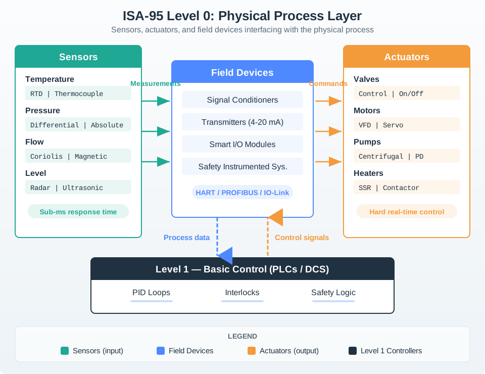
Figure 44.5: Level 0 values and commands are closest to the physical process, so stale data and misplaced authority can change machine behavior directly.
Mobile Figure Summary: Level 0 Data Flow
Sensors: Temperature, pressure, flow, and level devices send fast process measurements upward.
Field devices: Signal conditioners, transmitters, smart I/O, and safety systems normalize and route the data.
Actuators: Valves, motors, pumps, and heaters receive deterministic control commands from Level 1.
Control boundary: Level 1 PLC/DCS systems close the loop using sub-millisecond updates between measurements and commands.
Try it: Adjust the number of motors, signals per motor, sampling rate, feature-reduction factor, and illustrative transfer price to see how bandwidth assumptions change. Treat the output as a planning comparison, not a current cloud-price quote.
Key architectural decisions:
Edge processing: FFT, statistical features, and event extraction at Level 2 reduce the data published beyond the control zone.
Time-series storage: A historian or time-series database handles high-rate process values with timestamp, compression, and quality rules.
OPC-UA server: Provides a governed namespace for selected values and context.
Data lake: Raw or summarized data retention follows quality, compliance, and cost requirements.
Security: Network segmentation, OPC-UA encryption, VLANs separate control and IT networks
After edge processing: 1 Hz features = 6 KB/second to cloud
Reduction factor: 4,000×
Checkpoint: Assembly-Line Evidence
You now know:
The case has 100 robotic arms, 600 servo motors, 1,000 quality sensors, 50 AGVs, and 10 operator stations, so one shared timing path would be unsafe.
Robot synchronization is under 1ms with less than 1μs jitter, while ERP production counts are hourly batch updates.
Streaming 600 motors x 10 signals every 1ms creates 6 million samples/second, so edge reduction keeps raw control-loop data out of enterprise analytics.
Putting Numbers to It
An automotive assembly line with 600 servo motors, each reporting 10 signals (position, velocity, current, temperature, etc.) at 1ms intervals generates massive data volumes:
The reduction illustrates why raw control-loop data is usually not streamed unchanged to enterprise analytics. The exact cost depends on retention, compression, network path, cloud region, contract terms, and whether the data is stored, transferred, or queried.
Real-Time Systems Basics
What is “real-time”? It means the system must respond within a specific time limit. Think of it like a deadline:
Hard real-time: Like a goalkeeper – you MUST save the ball in time, or it is a goal. Missing the deadline is a failure (e.g., emergency stop must activate within 10ms).
Soft real-time: Like a bus schedule – being 2 minutes late is annoying but acceptable. Missing the deadline degrades quality but does not cause failure.
Best effort: Like postal mail – it arrives when it arrives, with no guaranteed delivery time.
What is ISA-95? It is a standard that organizes a factory into 5 floors (levels), each with different speed requirements. The bottom floors need lightning-fast responses (controlling machines), while the top floors handle slow business decisions (planning what to build next month).
The key rule: Always use the right tool for the right floor. You would not use a racing car to deliver furniture (too expensive), and you would not use a delivery truck to race in Formula 1 (too slow). Similarly, do not use cloud computing to control a robot arm, and do not use a PLC to run your ERP system.
Map Tech to ISA-95 Levels
When designing industrial IoT systems, the biggest mistake is using the wrong technology for the wrong level. This decision framework helps you match computing platforms, protocols, and architectures to automation levels.
Level
Timing
Example Application
Right Technology
Wrong Technology (Why)
0-1
<1ms
Servo motor control
PLC + EtherCAT
Cloud API (200ms latency – motor crashes before alert)
1-2
1-10ms
Discrete I/O, safety
PLC + PROFINET
Wi-Fi + MQTT (packet loss breaks safety)
2
100ms-1s
HMI displays
Industrial PC + SCADA
Consumer laptop (not rated for factory floor)
3
Seconds
MES batch tracking
On-prem server + OPC-UA
Edge gateway (insufficient compute for MES)
4
Minutes-hours
ERP planning
Enterprise cloud
PLC (PLCs don’t run SAP)
Decision Tree:
Q1: Does a missed deadline cause physical damage or safety risk?
Yes → Hard real-time (Levels 0-1) → Use PLC/PAC with deterministic network (EtherCAT, PROFINET IRT)
No → Proceed to Q2
Q2: Is response time under 100ms required?
Yes → Soft real-time (Level 1-2) → Use PLC with standard industrial Ethernet (PROFINET IO, EtherNet/IP)
No → Proceed to Q3
Q3: Does it involve human interaction or visualization?
Yes → Level 2 (SCADA/HMI) → Industrial PC with SCADA software (Ignition, WinCC)
No → Proceed to Q4
Q4: Does it coordinate production workflows or track quality?
Yes → Level 3 (MES) → Server-grade hardware with MES software (Siemens Opcenter, Rockwell FactoryTalk)
No → Proceed to Q5
Q5: Is it business planning, finance, or supply chain?
Yes → Level 4 (ERP) → Enterprise cloud or data center (SAP, Oracle)
Real Example – Assembly Line Robot:
Level 0-1: Servo drives (EtherCAT, <100μs cycle) – controls arm position
Level 3: MES server (OPC-UA, 10s) – tracks which product variant is running
Level 4: ERP cloud (REST API, 1 hour) – orders more parts when inventory low
Key Principle: Never use higher-level (slower) tech for lower-level (faster) requirements. The opposite is OK but wasteful – using EtherCAT for HMI updates works but costs 10× more than needed.
Real-Time and ISA-95 Links
Hard Real-Time → EtherCAT/PROFINET IRT: Deterministic protocols guarantee sub-millisecond response for Level 0-1 safety and motion control.
ISA-95 Levels → Technology Selection: Each level has distinct timing requirements: Field (μs), Control (ms), Supervisory (100ms), Operations (seconds), Enterprise (hours).
Jitter → Multi-Axis Synchronization: Timing variation between coordinated axes is more critical than absolute latency for precision motion.
OPC-UA → Level 2-3 Boundary: Bridges real-time control (PLCs) to business systems (MES/ERP) with semantic data models and security.
Cross-module connection: Industrial Protocols explains how EtherCAT achieves <100μs cycle times with <1μs jitter using time-triggered communication and distributed clocks for Level 0-1 hard real-time control.
Interactive Quiz: Match ISA-95 Concepts
Quiz: ISA-95 Design Sequence
Common Pitfalls
Not Every Message Is Control
A historian sample, an HMI alarm, an MES work-order update, and a drive command do not have the same deadline or authority. Classify each message by level, owner, deadline, stale-data behavior, and consequence before choosing a protocol.
Respect Layer Boundaries
MES, ERP, dashboards, and analytics systems may request, schedule, or record, but they should not bypass PLC, safety, or cell-level authority. Any write path from Level 3 or Level 4 into Level 0-1 needs explicit ownership, authorization, interlock, and rollback rules.
3. Measuring Only Network Latency
A real-time claim must include sensor delay, filtering, scan time, task priority, queueing, switch behavior, output update, actuator response, and safe fallback. A fast link can still miss a machine deadline if any queue or scheduler in the path is unbounded.
Label the Diagram
44.18 Code Challenge
44.19 Summary
Real-time requirements and ISA-95 levels provide a systematic framework for industrial system design:
ISA-95 pyramid: Five levels from field devices (sub-millisecond) to enterprise (hours-days) with distinct timing requirements and technologies appropriate to each level. The standard (IEC 62264) provides the definitive interface model between enterprise and control systems.
Determinism matters: Hard real-time systems require guaranteed worst-case timing with bounded jitter; soft real-time tolerates occasional delays with statistical QoS; best-effort has no timing guarantees. Choosing the wrong class can cause safety incidents (under-specifying) or wasted budget (over-specifying).
Jitter vs latency: For synchronized motion control, consistent timing (low jitter) is often more critical than absolute speed. IEEE 1588 PTP and EtherCAT distributed clocks provide sub-microsecond synchronization for multi-axis coordination.
Technology mapping: Protocol, computing platform, and network architecture choices must align with the timing requirements of each ISA-95 level. Use EtherCAT/PROFINET IRT for Level 0-1, PROFINET/EtherNet/IP for Level 1-2, OPC-UA for Level 2-3 bridging, and REST/MQTT for Level 3-4 cloud integration.
Design principle: Never use higher-level (slower) technologies for lower-level (faster) requirements. Cloud cannot control motors; PLCs should not run ERP. Design from the bottom up – secure the hardest real-time constraint first, then relax requirements as you ascend the pyramid.
44.20 See Also
Industrial Protocols — Comparison of EtherCAT, PROFINET IRT, EtherNet/IP with latency and jitter specifications for each ISA-95 level
Real-Time Operating Systems — VxWorks, QNX, RTAI architecture for guaranteed worst-case execution time (WCET) at Level 0-1
Time-Sensitive Networking — IEEE 802.1 TSN extensions for deterministic Ethernet suitable for industrial control
OPC-UA Standard — Level 2-3 integration protocol that bridges real-time control to business systems with semantic data models
In 60 Seconds
This chapter covers real-time & isa-95, explaining the core concepts, practical design decisions, and common pitfalls that IoT practitioners need to build effective, reliable connected systems.

 Checkpoint: Timing Ladder