21 Indoor Positioning: BLE Beacons and Ranging
More
Depth: Practitioner
Progress saves as you read. Mark sections complete as you go; your progress appears in the sidebar.
21.1 Overview
This section: Overview — This first route explains why indoor positioning differs from GPS, the satellite-based location system.
This first route explains why indoor positioning differs from GPS, the satellite-based location system. It then uses Bluetooth Low Energy (BLE) beacons, short-range radio transmitters, to estimate distance. That estimate is called ranging. The calibrated case uses measurements at known site points to tune and check the estimate.
This is part 1 of 2. Continue with Indoor Positioning: Wi-Fi, UWB, and Sensor Fusion for the second focused route.
21.2 Start Simple
This section: Start Simple — Picture a nurse looking for a cart on the third floor.
Find One Cart Without Promising Too Much
Picture a nurse looking for a cart on the third floor. A dot in the wrong room wastes time, while a system that admits uncertainty can guide a useful search.
Bluetooth Low Energy, or BLE, is a short-range radio system for small exchanges. Ultra wideband, or UWB, uses very short radio pulses for precise ranging. Each needs installed points and a measured site model.
Walk one marked route with a known cart. Record floor, room, estimate, error, confidence, time, missing signal, and fallback. Move people and doors, rotate the tag, lose one anchor, and repeat after layout changes.
This runway does not guarantee the same accuracy in every building. The deeper sections compare radio and sensor methods, calibration, mixed paths, privacy, handoff, and bounded location claims.
Indoor location starts by asking what decision the position must support inside the building. A room-level asset search, shelf-level retail prompt, and centimeter-level robot path need different infrastructure, calibration, privacy language, confidence, and fallback behavior.
This chapter is long, so use it as a guided design review.
- First define the indoor place model: room, floor, aisle, route, confidence, and degradation state.
- Then compare the radio, sensor, floor, camera, and check-in technologies against the job they must support.
- Next work through BLE, Wi-Fi fingerprinting, UWB, and sensor fusion examples with their calibration assumptions visible.
- Finally choose a technology stack, test its failure modes, and verify the answer with quizzes and hands-on exercises.
Checkpoint callouts recap the decision so far. Optional worked examples can be read as deep-dive evidence after the main path is clear.
21.3 Learning Objectives
This section: Learning Objectives
By the end of this chapter, you will be able to:
- Compare Indoor Positioning Technologies: Evaluate Wi-Fi, BLE, UWB, and ultrasonic systems for accuracy and cost
- Apply Trilateration Calculations: Compute position estimates from beacon distance measurements
- Design Sensor Fusion Systems: Combine GPS, Wi-Fi, BLE, and IMU for seamless indoor-outdoor transitions
- Troubleshoot Multipath Effects: Identify and mitigate RF interference in indoor environments
GPS does not work indoors — building walls attenuate satellite signals by 20-40 dB, making them too weak to use. So how do you track assets, guide visitors, or locate equipment inside a warehouse or hospital? Indoor positioning uses alternative technologies: BLE beacons (1-3 meter accuracy, cheap), Wi-Fi fingerprinting (3-5 meters using existing infrastructure), UWB (10-30 centimeter precision but expensive), and ultrasonic (3 centimeters but needs line-of-sight). Real-world systems combine multiple technologies with sensor fusion to provide seamless positioning as you walk from outdoors to indoors.
Key Concepts
This section: Key Concepts — GPS: Global Positioning System providing 3-10 metre outdoor accuracy using trilateration from 4+ satellites, consuming 20-100 mA active current.
GPS: Global Positioning System providing 3-10 metre outdoor accuracy using trilateration from 4+ satellites, consuming 20-100 mA active current. Indoor Positioning: Techniques (BLE beacons, UWB, Wi-Fi RSSI, IMU dead-reckoning) achieving 0.1-5 metre accuracy where GPS signals are unavailable. Geofencing: Virtual geographic boundary triggering automated actions when a tracked asset enters or exits the defined area. Dead Reckoning: Position estimation using last known location plus measured movement (speed, heading) when GPS signal is lost. RSSI-Based Positioning: Location estimation from signal strength of known beacon nodes, achieving 2-5 metre accuracy in calibrated environments. Ultra-Wideband (UWB): Radio technology providing 10-30 cm indoor positioning accuracy using time-of-flight measurements between anchor nodes. Location Privacy: User right to control who can access their location history and how granular that location data is stored.
21.4 Prerequisites
This section: Prerequisites — Start with the product promise, not the radio.
- Location Awareness Fundamentals: Understanding of positioning technology landscape
- GPS and Outdoor Positioning: Understanding of ToF, TDoA, and multipath concepts
Start with the product promise, not the radio. The first question is what kind of indoor answer a user or operation can act on.
21.5 Indoor Place in Building Models
This section: Indoor Place in Building Models — Indoor positioning is rarely about latitude and longitude.
Indoor positioning is rarely about latitude and longitude. The useful answer is usually a building, floor, room, aisle, doorway, dock, bed bay, exhibit, or safe walking route. That means the location system must connect radio or sensor measurements to a maintained floor plan, not just compute a coordinate.
Before reading the linked figure in Part 2, compare the user promises made from the same measured position. A visitor app may show "near gallery 4." A hospital equipment system may show "infusion pump in room 305." A warehouse workflow may show "pallet in aisle B, bay 12." A robot may need the coordinate, heading, obstacle state, and confidence before it moves.
the linked figure in Part 2 shows why the product promise should name the usable granularity. "Find a pump on this floor" is different from "guide a visitor to the lift," "confirm a worker entered a restricted zone," or "dock a robot to a charger." Each promise needs a different tolerance for floor errors, stale positions, latency, and privacy exposure.
A simple application taxonomy keeps the old localization vocabulary connected to product decisions. Location evidence can support indoor navigation, motion capture, warehouse or hospital object tracking, access control, SLAM-style mapping, headcount, event detection, weather-at-place services, car-navigation handoff, and nearby-printer selection. The evidence may come from RF measurements, LiDAR or camera maps, cameras on the user or in the environment, ultrasound or microphone timing, powerline or floor-load signatures, and IMU dead reckoning from acceleration and heading. GPS belongs in the handoff story: it can seed an outdoor fix or differential-reference correction, but it is not an indoor answer by itself.
Represent the answer at the level the application can defend. Some systems store absolute latitude-longitude or map coordinates. Others store a relative phrase such as "one bay north of the dock." Many user-facing systems store symbolic places such as "home," "work," "bedroom," "room 305," or "aisle B." Location can also be a proxy for activity, but only when the surrounding evidence supports that inference; proximity to a bed bay, vehicle, printer, or tool rack does not by itself prove what the person is doing.
Indoor systems also need explicit degradation states. If the app cannot distinguish room 305 from room 307, it should say "near rooms 305-307" or show a zone, not invent certainty. If a floor plan is old, if a beacon battery is low, or if an access point moved after the last Wi-Fi survey, the interface should lower confidence and invite confirmation instead of silently routing through walls.
- Semantic place: define the room, zone, shelf, doorway, floor, and route labels before choosing the radio technology.
- Confidence: show proximity, zone, or exact position based on the uncertainty and the consequence of being wrong.
- Ownership: keep beacon batteries, anchor locations, access-point changes, floor-plan versions, and recalibration on the operating plan.
 Checkpoint: Indoor Place Model
You now know:
- Indoor positioning usually returns a usable place such as a room, aisle, doorway, dock, bed bay, or safe walking route.
- The same measurement can support navigation, asset tracking, access control, SLAM-style mapping, or nearby-printer selection.
- A responsible interface shows lower confidence when it cannot distinguish rooms, floors, stale maps, moved access points, or low beacon batteries.
21.6 Match Tech to Indoor Jobs
This section: Match Tech to Indoor Jobs — BLE proximity, Wi-Fi fingerprinting, Wi-Fi RTT, UWB ranging, ultrasonic beacons, QR/NFC check-in, camera/vision, powerline fingerprinting, active floors, barometers, and IMU dead reckoning each fail differently.
BLE proximity, Wi-Fi fingerprinting, Wi-Fi RTT, UWB ranging, ultrasonic beacons, QR/NFC check-in, camera/vision, powerline fingerprinting, active floors, barometers, and IMU dead reckoning each fail differently. BLE advertising is inexpensive but RSSI changes with bodies, shelves, doors, and phone orientation. Wi-Fi fingerprinting can reuse access points but drifts when the building changes. Wi-Fi RTT using IEEE 802.11mc can improve range estimates when compatible access points and devices are available. Powerline positioning reuses electrical infrastructure but still needs a room-by-room signature map. Load-sensor floors can detect footsteps and gait accurately, but installation is invasive and multi-user separation is hard. UWB systems based on IEEE 802.15.4z can support precise ranging but need planned anchor geometry and site commissioning.
Design the indoor workflow around the tolerance. Room-level asset tracking can often tolerate BLE plus map constraints. Turn-by-turn visitor navigation needs route instructions, floor transitions, elevator/stair handling, and clear "you are near" language. Robot docking, augmented reality alignment, or high-value tool tracking may justify UWB anchors, calibration tags, tighter time synchronization, and alerts when anchor health degrades.
A classroom-style BLE localisation prototype is a useful minimum evidence path. The embedded device scans known beacons, records the beacon identifier, encounter time, and RSSI, then uploads the scan through a phone or Bluetooth gateway to a cloud service. Phase one proves the scan and upload path; phase two turns those records into a propagation model, distance estimate, placement assumption, and visualisation that a user can interpret. Keep the device, gateway, cloud API, and dashboard responsibilities separate so a working graph is not mistaken for proof that localisation itself is accurate.
Commissioning should be treated as part of the product, not as a one-time installation chore. Walk the building with known test points, record expected floor and room labels, validate lifts and stairwells separately, and include difficult cases such as crowded corridors, metal shelving, glass partitions, equipment rooms, and phone-in-pocket movement. Keep a small regression route so every firmware update, map revision, anchor move, or access-point replacement can be checked against the same evidence.
For UX decisions, expose the accuracy class rather than the raw technology label. A clinician needs "in room 3A, last seen 22 seconds ago," not "UWB anchor set 4 residual 0.21 m." A visitor may need a walking instruction plus a "recenter" button. An operations dashboard may need battery health, stale anchors, survey age, and the percentage of events corrected by map matching.
- Map the places: give every room, aisle, shelf, anchor, beacon, access point, and transition a stable id and map version.
- Set the handoff rules: define how GPS, BLE, Wi-Fi, UWB, IMU, barometer, QR, and manual confirmation combine when someone enters or leaves a building.
- Plan recalibration: schedule checks after access-point moves, beacon battery changes, shelf rearrangement, construction, and seasonal occupancy changes.
21.7 Indoor Accuracy Needs Infrastructure
This section: Indoor Accuracy Needs Infrastructure — An indoor location event should include more than x/y coordinates.
An indoor location event should include more than x/y coordinates. Useful fields include floor id, map version, source technology, beacon or anchor ids, RSSI, path-loss model, UWB range residuals, Wi-Fi BSSID list, Wi-Fi RTT distance estimates, accelerometer step count, gyroscope heading, barometric floor estimate, confidence score, age of observation, and whether map constraints changed the raw estimate.
Keep the measurement model visible to operations. BLE beacons may use iBeacon, AltBeacon, or ordinary Bluetooth LE advertising payloads. UWB anchors need known coordinates, clock behavior, channel configuration, and non-line-of-sight detection. Wi-Fi fingerprints need survey-device metadata and re-survey dates. Sensor-fusion code should preserve source weights and rejection reasons so a support team can tell whether the issue is a missing beacon, a moved access point, a bad floor plan, or a phone sensor problem.
Different estimators fail for different mathematical reasons. BLE RSSI ranging depends on a log-distance path-loss exponent, so a concrete corridor, a human body, or a metal cabinet can turn a small RSSI change into metres of distance error. Wi-Fi fingerprinting is a nearest-neighbour or probabilistic match against a surveyed signal database, so it fails when the database no longer represents the building. UWB two-way ranging and time-difference-of-arrival systems depend on timestamp precision, anchor geometry, clock handling, and non-line-of-sight rejection.
The algorithm names describe what information the system trusts. Proximity chooses the nearest beacon or zone. Lateration estimates position from distances to known anchors; trilateration is the familiar two- or three-dimensional case, while hyperbolic lateration uses time-difference-of-arrival curves. Triangulation uses angles. Fingerprinting compares an observed signal vector with a surveyed database. Distance estimates can come from time of flight, round-trip time, time difference of arrival, or signal-strength attenuation, and each method needs its own calibration and line-of-sight assumptions.
Start the geometry comparison with Figure 21.1. Identify the two fixed references, then follow the constant arrival-time difference to the hyperbola on which the device must lie. One receiver pair does not yield a unique point; a second independent curve is needed to create the crossing. This makes the infrastructure requirement visible before the chapter compares installed systems.

Figure 21.1 shows that the crossing is the estimate and that its shape depends on reference placement and timing quality. Poor geometry or clock disagreement widens the plausible region even when every receiver reports a value. That leads to a simpler historical design in Figure 21.2: a system that reports room-level proximity instead of solving continuous coordinates.
Classic indoor-location systems make those choices concrete. Active Badge used infrared proximity at Olivetti Research Laboratory. Active Bat used ultrasonic time-of-flight pings to reach roughly 3-10 cm resolution. UbiSense used 6-8 GHz UWB with time-delay and angle-of-arrival evidence, often trading 15-30 cm accuracy against line-of-sight and installation difficulty. RADAR treated Wi-Fi signal strength as a fingerprinting problem with about 3-5 m resolution, while PlaceLab combined multiple crowdsourced radio observations. Before inspecting Figure 21.2, look for the worn identifiers, the ceiling receiver, and the room-level outcome; the design intentionally answers “which room?” rather than “which coordinates?”

Figure 21.2 shows each badge's unique infrared pulse reaching the fixed room sensor and then informing the call-routing decision. Infrared line of sight and receiver placement bound the result, but the coarse answer fits the service. For tasks that require a point rather than a room, Figure 21.3 shows the extra directional evidence that triangulation consumes.

Figure 21.3 shows each receiver contributing a bearing rather than a distance, with the bearing lines intersecting at the transmitter estimate. Nearly parallel bearings make that intersection unstable, so placement geometry remains part of the accuracy promise. Together these three views show why “more infrastructure” means maintaining reference coordinates, clocks or bearings, line of sight, and a tested service boundary—not merely installing more radios.
Cellular and visible-light systems sit at the edge of the same design space. A phone can be localized coarsely by the cellular network because it must register with a base station; that basic cell-of-origin estimate is kilometre-scale and depends heavily on how dense the surrounding cell sites are (a dense urban grid resolves much better than a sparse rural one). Denser deployments can add uplink time-difference-of-arrival (U-TDoA) evidence, which correlates the same uplink signal's arrival time across multiple base stations to sharpen the estimate to roughly 30-400 m depending on how much multipath the signal picked up on the way in, but the result is still usually a zone or emergency-location fallback rather than room-level proof. Visible-light positioning reverses the beacon idea. Read Figure 21.4 from the coded ceiling fixtures to the phone camera and then to the fixture-to-place lookup; every stage depends on an unobstructed optical path and a maintained identifier map.

Figure 21.4 shows three luminaires emitting distinct binary identities faster than a person notices, while the camera decodes the nearest usable pattern. The result is only as reliable as fixture visibility, camera orientation, lighting conditions, and the current lamp-location map. This final example connects the estimator survey back to operations: every accuracy claim carries a physical installation and recalibration obligation.
Project Tango-style phone localization is a useful camera/IMU boundary case. Moving computation onto the client avoids a central vision server, but the device still has to fuse motion tracking, depth perception, and area learning into a map it can relocalize against. The review record should name the depth sensor or camera mode, IMU calibration, learned-area version, relocalization failure behavior, privacy boundary for captured scenes, and whether the result is used for navigation, augmented reality alignment, or only a demonstration.
There is no one-size-fits-all localization stack. Higher accuracy usually costs more anchors, calibration, power, maintenance, and deployment effort. A headcount dashboard may only need zone-level Wi-Fi or camera evidence. Access control may need conservative geofence margins. Motion capture, robot docking, and AR alignment may justify UWB, vision, LiDAR, or tighter fusion because the cost of a wrong position is much higher.
Fusion layers normally combine absolute measurements with motion and map constraints. A Kalman filter, particle filter, or hidden Markov model can carry uncertainty through time, reject impossible wall crossings, prefer corridor paths, and smooth handoffs between GPS, Wi-Fi, BLE, UWB, IMU, and barometer signals. The important engineering output is not just the best estimate; it is the covariance, source weights, rejected observations, and freshness metadata that decide whether the UI should show a dot, a zone, or a warning.
- Geometry risk: anchors or beacons clustered on one wall produce unstable estimates even if signal strength looks high.
- Map risk: a good coordinate on an old floor plan can route a user through a wall, locked door, or closed ward.
- Privacy risk: collect room-level or zone-level events when exact paths are unnecessary, and make retention match the operational need.
With the place model and maintenance plan established, the next question is why outdoor GPS is the wrong starting point indoors.
Angle of arrival can look geometrically exact until a wall adds another path. Figure 21.5 derives the direct bearing and then shows the reflected false solution.

Panel A, direct path, in Figure 21.5 maps ΔL = d sin θ into Δφ = 2πΔL/λ for antennas spaced d = λ/2. At θ = 30°, the path difference is λ/4, so the phase difference is π/2 radians. Panel B adds an echo from a reflector; the same array now receives two plausible phase differences. Geometry alone cannot decide which bearing is real, so placement, channel evidence, confidence, and a non-line-of-sight fallback must constrain the angle estimate.
The diagram states the risk; the workbench below makes it testable with the same half-wavelength geometry. Start with the direct path, then change only Reflected-path amplitude to see why an ambiguity-free LOS candidate can coexist with a badly biased observed bearing.
UWB angle of arrival narrated tour
Narrated audio tour. The full transcript is below.
Play the tour to open the workbench. Pause, replay a beat, or read the full transcript below. Some situations cannot be shown by this teaching model; those beats keep the existing frame and provide captions only.
Full transcript — UWB angle of arrival (8 beats)
B1 — Cart search
You are a nurse searching for a tagged cart on the third floor. A location dot in the wrong room wastes your time. Your equipment system offers a direction toward the cart. How much does the direction really tell you?
Model caption: You are a nurse finding a tagged cart on the third floor. A wrong-room dot wastes time. The asset illustrates direction evidence, not the hospital workflow.
B2 — Bearing and position
Ultra wideband, or UWB, uses very short radio pulses for precise ranging, meaning distance measurement. Our example concerns its angle of arrival: the direction a signal comes from, also called a bearing. A position combines bearing with distance or additional receivers. Bluetooth Low Energy, or BLE, is a different radio system; our example models UWB.
Model caption: Ultra wideband (UWB) uses short radio pulses. Angle of arrival is a bearing, or direction. Bearing combines with distance or additional receivers for position. Bluetooth Low Energy (BLE) is a different radio system.
B3 — Path and phase
Imagine two receiving antennas. A wave reaches one before the other because its travel paths differ. The received waves have an offset called a phase difference. Wavelength means the length of one wave cycle. Antenna spacing connects the path difference to an arrival angle in the model.
Model caption: Two antennas receive waves with different travel paths. The received-wave offset is a phase difference. Wavelength is one spatial cycle; antenna spacing connects path difference to arrival angle in the model.
B4 — Direct-path example
Measure angles from straight ahead of the antenna pair, with positive and negative angles on opposite sides. Take an ideal direct signal arriving at plus thirty degrees, with antennas half a wavelength apart. At thirty degrees, the geometry makes the path difference half the antenna spacing. Half of half a wavelength is one quarter of a wavelength. That path difference produces a phase offset of one quarter of a wave cycle. With no reflection, the model estimates plus thirty degrees, matching the true direction.
Model caption: True angle +30°; spacing half a wavelength; path difference one quarter wavelength; phase difference one quarter cycle. With reflection amplitude zero, the sole candidate and estimated bearing are both +30°.
B5 — Spacing ambiguity
Spacing ambiguity means different directions can fit the same phase difference. Half-wavelength spacing removes the ambiguity in the ideal direct-path model. For our thirty-degree example, the direct-path calculation gives a single possible direction: plus thirty degrees.
Model caption: Spacing ambiguity: different directions fit the same phase evidence. Half-wavelength spacing removes ideal direct-path spacing ambiguity. The candidate set for this example is [+30°].
B6 — Reflected-path bias
Add a reflection arriving at zero degrees, travelling an extra five eighths of a wavelength. Raise its amplitude, or wave strength, from zero to zero point seven five relative to the direct signal. Keep the antenna spacing and true direction fixed. The waves combine, and the estimated bearing becomes about minus seventy-four degrees. The direct-path calculation still gives plus thirty degrees.
Model caption: Reflection angle 0°; excess path five eighths wavelength; amplitude 0.750 relative to the direct signal. True direction +30° and spacing half a wavelength stay fixed. Estimated bearing ≈−74°; direct-path candidate +30°.
B7 — One candidate, wrong bearing
A common mistake is to assume one possible direction makes the estimate reliable, but reflections can still bias it. Half-wavelength spacing removes ideal spacing ambiguity. Reflections introduce a separate problem: the antennas receive the combined direct and reflected waves. The ideal direct-path calculation can give one possible direction while the combined waves produce an estimate far from the true direction. For your cart search, that difference matters.
Model caption: Misconception: half-wavelength spacing guarantees the correct bearing. The receiver combines direct and reflected waves, so a single ideal candidate (+30°) can coexist with a biased estimate (≈−74°).
B8 — Bearing takeaway
Half-wavelength spacing can settle ideal angle ambiguity; it cannot make a reflection tell the truth.
Model caption: Half-wavelength spacing can settle ideal angle ambiguity; it cannot make a reflection tell the truth.
21.8 Why Indoor Positioning is Different
This section: Why Indoor Positioning is Different — Satellite signals are extremely weak (~10^-16 watts received).
GPS doesn’t work indoors because:
Satellite signals are extremely weak (~10^-16 watts received). Building materials attenuate signals by 20-40 dB. Multipath from walls, ceilings, and furniture creates severe interference. No line-of-sight to satellites in most buildings.
This requires alternative technologies designed for indoor environments.
21.9 Indoor Positioning Technologies
This section: Indoor Positioning Technologies — Use Figure 21.6 to compare indoor location methods against the action they must support.
Use Figure 21.6 to compare indoor location methods against the action they must support.
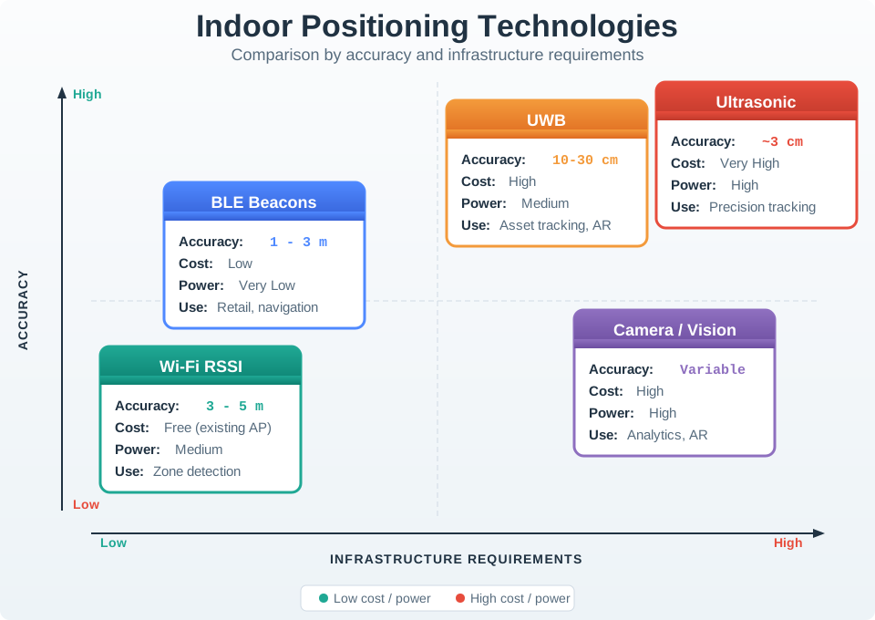
BLE beacons need installed transmitters and suit a different accuracy and power tradeoff from Wi-Fi RSSI, which can use existing infrastructure for broader zones. UWB needs anchors for tighter position estimates, while ultrasonic systems need their own sensors. The table includes cost, power, and use case because an accuracy range alone cannot choose a method. Treat the listed ranges as examples to test in the target building. Walls, device placement, and update interval can change whether the estimate is useful for the product action.
| Technology | Accuracy | Infrastructure | Cost | Power | Use Case |
|---|---|---|---|---|---|
| BLE Beacons | 1-3m | Deploy beacons | Low | Very Low | Retail, navigation |
| Wi-Fi RSSI | 3-5m | Use existing | Free | Medium | Zone detection |
| UWB | 10-30cm | Deploy anchors | High | Medium | Asset tracking, AR |
| Ultrasonic | 3cm | Deploy sensors | Very High | High | Precision tracking |
| Camera/Vision | Variable | Deploy cameras | High | High | Analytics, AR |
| Powerline fingerprinting | Room/zone | Use electrical wiring | Low-Medium | Low | Infrastructure reuse |
| Active floor/load sensors | Footstep/gait | Instrument floor | Very High | Medium | Accurate presence or gait sensing |
21.10 BLE Beacon Positioning
This section: BLE Beacon Positioning — BLE beacons continuously broadcast identifier packets.
BLE beacons continuously broadcast identifier packets. Smartphones detect these signals and estimate distance based on Received Signal Strength Indication (RSSI).
The simple exchange in Figure 21.7 shows what a BLE beacon broadcasts and what a receiver observes.
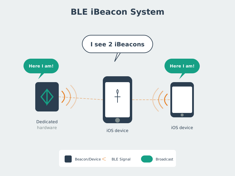
A beacon sends a signal that nearby devices can detect; the phone in the figure sees two iBeacons. That observation establishes proximity evidence, not a precise position by itself. The application still has to compare signals, know where beacons are installed, and decide what action the estimate can support. Check reception in the real room and at its boundaries before promising a zone change. A weak or missing broadcast should lead to an uncertain state rather than a silently confident location.
21.10.1 RSSI-Based Distance Estimation
The relationship between RSSI and distance follows a path loss model:
Solving for distance:
Where:
- TxPower = Measured RSSI at 1 meter (typically -59 dBm)
- n = Path loss exponent (2.0 in free space, 2.5-4.0 indoors)
- d = Distance in meters
Interactive Insight: Notice how the path loss exponent dramatically affects distance estimates. Changing n from 2.0 to 3.0 can change estimated distance by 40-60%. In a concrete hospital (n=3.2), a beacon showing -72 dBm is only 2.5 meters away, but the same reading in an open office (n=2.5) suggests 3.3 meters — a 30% error.
Scenario: A retail store deploys BLE beacons for indoor customer navigation. The positioning system uses trilateration from RSSI measurements to estimate shopper location.
Given:
Beacon A at position (0, 0) meters, measured RSSI = -65 dBm. Beacon B at position (10, 0) meters, measured RSSI ≈ −82.3 dBm. Beacon C at position (5, 8) meters, measured RSSI ≈ −81.6 dBm. Calibrated path loss model: RSSI = -59 dBm at 1 meter, path loss exponent n = 2.5. Distance formula: d = 10^((TxPower - RSSI) / (10 x n)).
Steps:
Calculate distance from Beacon A:. d_A = 10^((-59 - (-65)) / (10 x 2.5)) = 10^(6/25) = 10^0.24 = 1.74 meters.
Calculate distance from Beacon B:. d_B = 10^((-59 - (-82.3)) / (10 x 2.5)) ≈ 8.54 meters.
Calculate distance from Beacon C:. d_C = 10^((-59 - (-81.6)) / (10 x 2.5)) ≈ 8.01 meters.
Apply trilateration equations:. Circle A: x^2 + y^2 = 1.74^2 = 3.03. Circle B: (x−10)^2 + y^2 ≈ 72.89. Circle C: (x−5)^2 + (y−8)^2 ≈ 64.09. Solving these approximate circles gives a position near (1.5, 0.8) m.
Result: This illustrative position is near Beacon A. RSSI uncertainty changes each estimated range; quantify position error with calibrated site measurements before reporting a confidence bound or room assignment.
Key Insight: BLE trilateration depends on path-loss calibration. Changing the path-loss exponent changes the range estimates and therefore the position; calibrate it on site.
Checkpoint: BLE Ranging
You now know:
- BLE beacons are attractive when low cost, low power, and room or aisle guidance matter more than centimeter precision.
- RSSI distance estimates depend on TxPower, the path loss exponent, and real building materials.
- Trilateration can produce a useful zone estimate, but the result should carry uncertainty because RSSI noise and geometry move the fix.
21.11 Continue to Part 2
This section: Continue to Part 2 — Continue with Indoor Positioning: Wi-Fi, UWB, and Sensor Fusion.
Continue with Indoor Positioning: Wi-Fi, UWB, and Sensor Fusion.
Find help
3 reviewed answers.
Where should I start in a module?
Open the module page from the sidebar to see its chapters in order. Use the module map to return to a topic you need.
Modules and pathsReviewed
What can I try when a project does not work?
Check the symptom, then work through the diagnostic steps. Keep the error message and the smallest example that reproduces it.
When you are stuckReviewed
How do interactive examples work?
Use the interactive guide to check how examples and simulations work before changing your project.
Interactive examples guideReviewed