23 GPS Accuracy: Error Budgets
More
Depth: Practitioner
Progress saves as you read. Mark sections complete as you go; your progress appears in the sidebar.
23.1 Overview
This section: Overview — This first route explains accuracy promises, error sources, geometry, and a calculated GPS error budget.
This first route explains accuracy promises, error sources, geometry, and a calculated GPS error budget.
This is part 1 of 2. Continue with GPS Accuracy: Enhancement Decisions for the second focused route.
23.2 Start Simple
This section: Start Simple — An accuracy upgrade matters only if it changes the connected-product decision.
An accuracy upgrade matters only if it changes the connected-product decision. Start with the action, tolerance, confidence, update interval, cost, and recovery path, then decide whether DGPS, SBAS, RTK, PPP, or a simpler fix actually improves the user outcome.

23.3 Summary
This section: Summary — GPS accuracy is controlled by error sources, satellite geometry, correction methods, receiver behavior, and the deployment environment.
GPS accuracy is controlled by error sources, satellite geometry, correction methods, receiver behavior, and the deployment environment. Accuracy design should match application risk and cost, from basic asset tracking to centimeter-level RTK control.
23.4 Learning Objectives
This section: Learning Objectives
By the end of this chapter, you will be able to:
- Analyze GPS Error Budget: Explain the contribution of each error source to total positioning uncertainty
- Calculate UERE: Apply root-sum-square to combine independent error sources into a single accuracy metric
- Compare Enhancement Technologies: Evaluate DGPS, SBAS, RTK, and PPP against specific accuracy requirements
- Design for Accuracy Requirements: Justify the selection of appropriate positioning technology for specific IoT applications
Standard GPS can provide 5–10 meter accuracy under open sky, but many IoT applications need better. This chapter breaks down where GPS errors come from; in the chapter’s illustrative error budget, ionospheric delay accounts for about 72% of UERE². Enhancement technologies can improve accuracy, and the right choice depends on the application.
Key Concepts
This section: Key Concepts — GPS: Global Positioning System providing 3-10 metre outdoor accuracy using triangulation from 4+ satellites, consuming 20-100 mA active current.
GPS: Global Positioning System providing 3-10 metre outdoor accuracy using triangulation from 4+ satellites, consuming 20-100 mA active current. Indoor Positioning: Techniques (BLE beacons, UWB, Wi-Fi RSSI, IMU dead-reckoning) achieving 0.1-5 metre accuracy where GPS signals are unavailable. Geofencing: Virtual geographic boundary triggering automated actions when a tracked asset enters or exits the defined area. Dead Reckoning: Position estimation using last known location plus measured movement (speed, heading) when GPS signal is lost. RSSI-Based Positioning: Location estimation from signal strength of known beacon nodes, achieving 2-5 metre accuracy in calibrated environments. Ultra-Wideband (UWB): Radio technology providing 10-30 cm indoor positioning accuracy using time-of-flight measurements between anchor nodes. Location Privacy: User right to control who can access their location history and how granular that location data is stored.
23.5 Prerequisites
This section: Prerequisites
- GPS and Outdoor Positioning: Understanding of GPS fundamentals and error sources
This chapter is long because location accuracy is both a measurement problem and a product promise.
- First you decide what the user is allowed to trust from a location fix.
- Then you break the fix into receiver state, geometry, correction data, and environment symptoms.
- Next you calculate UERE and GDOP so the accuracy number is explainable.
- After that you compare standard GPS, SBAS, DGPS, RTK, PPP, and indoor fallbacks against real IoT jobs.
- Finally you check the cost, power, safety, quiz, and lab consequences of choosing the wrong tier.
Checkpoint callouts recap the main design decisions. Deep technical panels and calculators are useful references, but you can return to them after the first read.
23.6 Accuracy as Product Promise
This section: Accuracy as Product Promise — First, treat accuracy as a contract between the system and the person acting on its output.
First, treat accuracy as a contract between the system and the person acting on its output.
Location accuracy affects what a user is allowed to trust. A tracker that says a shipment is “at the depot” can tolerate a different error band from a campus robot that decides whether it is on a sidewalk, a farm machine that follows a crop row, or an emergency alert that chooses which building entrance to show responders.
Design the user experience around the useful accuracy interval, not the best number in a datasheet. The same GNSS receiver may report a good open-sky fix, a weak urban-canyon fix, a stale assisted-GPS estimate, or no fix indoors. The interface should make that state visible with bounded language such as “near loading bay 3,” “last seen 4 minutes ago,” or “centimeter guidance unavailable; manual steering required.”
Use Figure 23.1 to define the product action before picking a location signal.
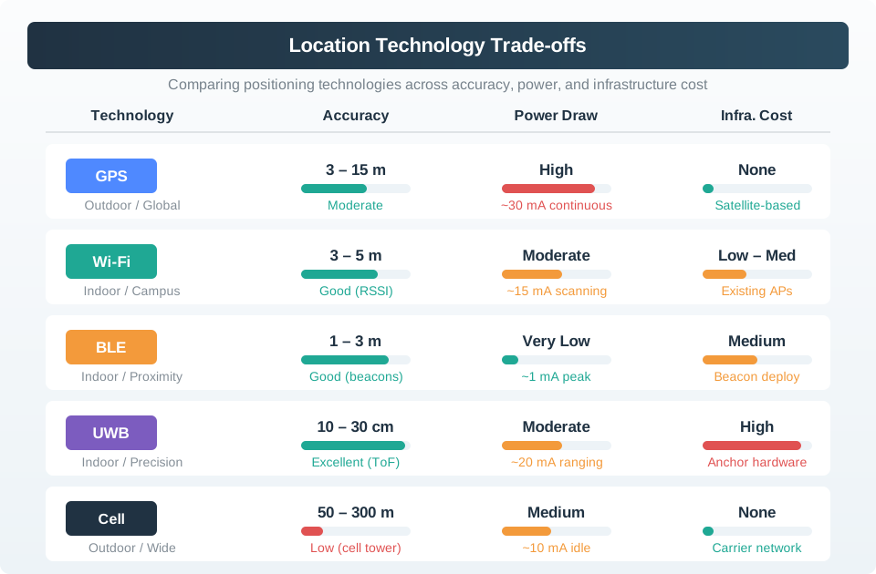
First state the action that location will trigger. Set the largest error it can bear, how sure the fix must be, and how often it must update. Record power, upkeep, and what happens if the fix is weak. Then compare cellular, Wi-Fi, BLE, and other signals in the target setting. The indoor handoff shows why no signal works the same everywhere. Test each method on the device at the planned rate. When confidence falls, switch sources, ask for a check, or stop the action.
Fit for purpose: match the displayed precision to the task, cost, power budget, and risk of being wrong. State clarity: distinguish live fix, degraded fix, estimated position, and stale position before users act on it. Fallback: switch to Wi-Fi, BLE, UWB, IMU dead reckoning, computer vision, manual confirmation, or a safe stop when GNSS no longer supports the task.
The product promise should name the decision boundary. “Open the gate” might require enough confidence to know the vehicle is at the entrance and moving slowly. “Show a child at school” might need a zone and a recent timestamp, not an exact coordinate. “Guide a tractor row” might require a fixed RTK state and an alarm when correction data is stale. The same latitude and longitude can be acceptable for one feature and unsafe for another.
Accuracy also changes over time. Satellite geometry shifts, antennas are shadowed by a trailer or building, leaves and wet glass create multipath, a correction stream ages, and an indoor handoff may depend on Wi-Fi, BLE, UWB, barometer, or IMU data. A good interface does not show extra decimal places just because the API returns them. It shows uncertainty circles, zone labels, stale markers, disabled buttons, confidence bands, or manual confirmation when the error estimate crosses a product threshold.
For IoT designers, the important question is usually not “what is the most accurate technology?” It is “what is the cheapest, lowest-power, maintainable signal that keeps the feature honest?” Shipping containers, delivery fleets, farm guidance, drones, indoor assets, personal safety wearables, and campus robots can all need different combinations of GNSS, SBAS, DGPS, RTK, PPP, Wi-Fi positioning, BLE proximity, UWB ranging, vision, lidar, and human confirmation.
23.7 Accuracy UI Rules
This section: Accuracy UI Rules — Start with the action that location enables.
Start with the action that location enables. For a shipping container, the question may be “which yard or gate?” For a delivery driver, it may be “which side of the street?” For precision agriculture, it may be “is the tractor centered within a few centimeters?” Each action needs a stated tolerance, update interval, confidence level, fallback, and user message.
Useful implementation signals include HDOP or GDOP, estimated horizontal and vertical accuracy, fix type, satellite count, correction age, carrier-phase fix status, time since last fix, speed, heading, battery state, antenna fault, and whether the receiver is using standalone GNSS, SBAS such as WAAS or EGNOS, DGPS, RTK, PPP, or sensor fusion. Store those signals with the location event so support staff can see why the product showed a coarse zone instead of an exact point.
- Write a tolerance table: connect each feature to a maximum horizontal error, vertical error if relevant, update cadence, and allowed fallback.
- Choose honest display language: show zones, uncertainty circles, “last known” timestamps, or disabled controls when the fix does not meet the tolerance.
- Test hard places: include open sky, tree cover, warehouse entrances, street canyons, tunnels, high-rise approaches, and indoor handoff points.
Translate the tolerance table into UI states and automation guards. A dashboard might show a green “RTK fixed” badge only when correction age, satellite count, and covariance are inside bounds. A mobile app might label a delivery as “near the entrance” instead of pinning it to a door when the reported horizontal accuracy is wider than the building frontage. A robot controller might slow down, request vision confirmation, or stop when the uncertainty radius overlaps a curb, crop row, loading dock edge, or restricted zone.
Field validation should use representative routes, not a lab bench alone. Walk or drive the system through open fields, metal warehouses, tree cover, alleyways, tunnels, parking structures, high-rise entrances, and transition zones between outdoor GNSS and indoor positioning. Record the displayed state, raw receiver state, correction source, power draw, network availability, and user action taken. Those traces become regression tests for later firmware, antenna, map, or dashboard changes.
Cost review belongs in the same design pass. RTK can be justified when centimeter error prevents crop damage, grading mistakes, or unsafe vehicle movement, but it may be wasteful for asset tracking or large geofence alerts. Conversely, a cheap receiver is not cheap if it causes false arrivals, missed stops, manual dispatch calls, damaged products, or unsafe robot behavior. The design record should state why the chosen accuracy tier is enough and what the system does when it is not enough.
This section:
Checkpoint: Product Accuracy Contract
You now know:
- The right accuracy is the one that supports the product action, not the smallest number in a datasheet.
- A location event should carry fix state, confidence, stale time, correction status, and fallback language.
- Field tests must include the hard places where users actually depend on the result.
This section:
23.8 Corrections Need Visible Errors
This section: Corrections Need Visible Errors — Now connect that product contract to the signals coming out of the receiver and correction service.
Now connect that product contract to the signals coming out of the receiver and correction service.
GNSS accuracy is built from measurement quality, satellite geometry, correction data, and receiver state. L1/L2/L5 measurements, GPS/Galileo/GLONASS/BeiDou satellite availability, C/N0 signal quality, ephemeris age, ionospheric and tropospheric models, multipath rejection, antenna placement, and receiver clock behavior all affect the reported fix. SBAS broadcasts wide-area corrections. DGPS uses a nearby reference station. RTK uses carrier-phase measurements and needs continuous lock. PPP relies on precise orbit and clock products and usually has convergence time.
The system boundary matters as much as the math. RTK correction streams may arrive over NTRIP using RTCM 3 messages, local radios, or a vendor cloud service. If the correction age grows, the rover loses fixed status, the antenna is shadowed, or the receiver falls back from RTK fixed to float or standalone GNSS, the product must stop presenting centimeter-level confidence. Logs should preserve fix type, covariance or accuracy estimate, correction source, correction age, geofence decision, command id, map-matching result, and the message shown to the user.
- Correction scope: DGPS and SBAS reduce shared satellite, clock, and atmospheric errors; they do not remove local multipath from glass, metal, trees, or bad antenna placement.
- Safety boundary: when error exceeds the clearance needed for steering, docking, routing, or emergency response, slow down, ask for confirmation, or switch control mode.
- Privacy boundary: collect only the accuracy needed for the feature; a zone event can be enough when a continuous coordinate trail would expose unnecessary movement history.
Mathematically, the receiver is estimating position from noisy range observations. UERE captures range error sources, while DOP describes how satellite geometry amplifies those errors into position uncertainty. A low-noise receiver with poor geometry can still produce a poor position. A good correction stream cannot remove a reflection from a nearby wall if the antenna receives a delayed signal path. That is why reliable products track both source quality and environment symptoms.
Sensor fusion adds another layer of contracts. An extended Kalman filter or similar estimator can combine GNSS, wheel odometry, IMU acceleration, magnetometer heading, barometer altitude, camera lane detection, lidar obstacles, Wi-Fi fingerprints, BLE proximity, and UWB ranges. The fused output should expose covariance, source contributors, last update time, and fault flags so downstream automation can decide whether the estimate is suitable for display, routing, steering, billing, or only historical logging.
Persistence should keep enough evidence to debug bad decisions without storing unnecessary movement history. A compact event can include fix_type, horizontal_accuracy, vertical_accuracy, hdop, satellite_count, correction_age, correction_source, map_version, fusion_mode, confidence, stale_after, and the user-visible label. For privacy-sensitive features, store a zone or decision result unless raw coordinates are required for a short-lived operational reason.
This section:
Checkpoint: Error Evidence
You now know:
- SBAS, DGPS, RTK, and PPP improve different parts of the error stack.
- Local multipath, blocked antennas, correction age, and fix type still have to be surfaced to the product.
- Logs should preserve enough evidence to explain why the interface showed a zone, warning, disabled control, or precise point.
This section:
23.9 GPS Error Budget Basics
This section: GPS Error Budget Basics — With the contract and evidence fields in place, the next question is how to calculate the error number itself.
With the contract and evidence fields in place, the next question is how to calculate the error number itself.
Understanding where GPS accuracy comes from—and where it breaks down—is critical for designing reliable IoT location services. A GPS error budget quantifies each error source’s contribution to total positioning uncertainty.
23.9.1 Error Budget Breakdown
The table below shows the six main error sources, their typical magnitude, how variable they are, and how we can mitigate them:
| Error Source | Typical Error | Notes |
|---|---|---|
| Satellite clock | 1.5 m | Atomic clock drift compensated by ground uploads every 15 minutes |
| Ephemeris data | 2.5 m | Orbital prediction errors; frequent updates every 2 hours minimize drift |
| Ionospheric delay | 5.0 m | Varies with solar activity; equatorial regions 2-3× worse than poles |
| Tropospheric delay | 0.5 m | Weather dependent; humidity and temperature affect signal propagation |
| Multipath | 1.0 m | Urban canyons worst case; signals bounce off buildings creating echoes |
| Receiver noise | 0.3 m | Hardware quality dependent; better RF front-ends reduce noise floor |
| Total (UERE) | ~6 m | Root sum square of all independent error sources |
| With DGPS | <1 m | Differential correction removes common-mode errors (ionosphere, clock) |
| With RTK | <2 cm | Real-time kinematic uses carrier phase for centimeter-level precision |
GPS errors don’t simply add up—they combine using root sum square (RSS) because they’re independent random variables:
Why RSS and not simple addition? If errors added linearly, total would be 10.8 meters. But some errors cancel each other out randomly, resulting in the more realistic 6-meter UERE.
Let’s calculate the actual error budget for a GPS receiver in three different environments to see how context affects accuracy.
Scenario 1: Rural open sky (best case)
Given error sources:
- Satellite clock: m
- Ephemeris: m
- Ionosphere: m (low solar activity, mid-latitude)
- Troposphere: m
- Multipath: m (no reflective surfaces)
- Receiver noise: m
With excellent satellite geometry (hypothetical HDOP = 1.5):
Scenario 2: Urban canyon (worst case)
Same base errors, but:
- Ionosphere: m (standard)
- Multipath: m (signals bounce off glass buildings)
Poor satellite geometry (only 4 satellites visible overhead, hypothetical HDOP = 6.5):
Scenario 3: Equatorial region, solar storm
- Ionosphere: m (extreme solar activity)
With hypothetical HDOP = 2.0:
Key insight: In these examples, the same GPS receiver’s horizontal one-sigma uncertainty ranges from 6.3 m (rural) to 44 m (urban canyon) under the stated hypothetical HDOP values. In the baseline worked input, ionospheric delay contributes about 72% of UERE², rising to roughly 94% in the solar-storm input (each source’s share is its variance divided by UERE², so the shares sum to 100% of UERE²).
The variance shares in Figure 23.2 identify which independent sources contribute most to the total range error.
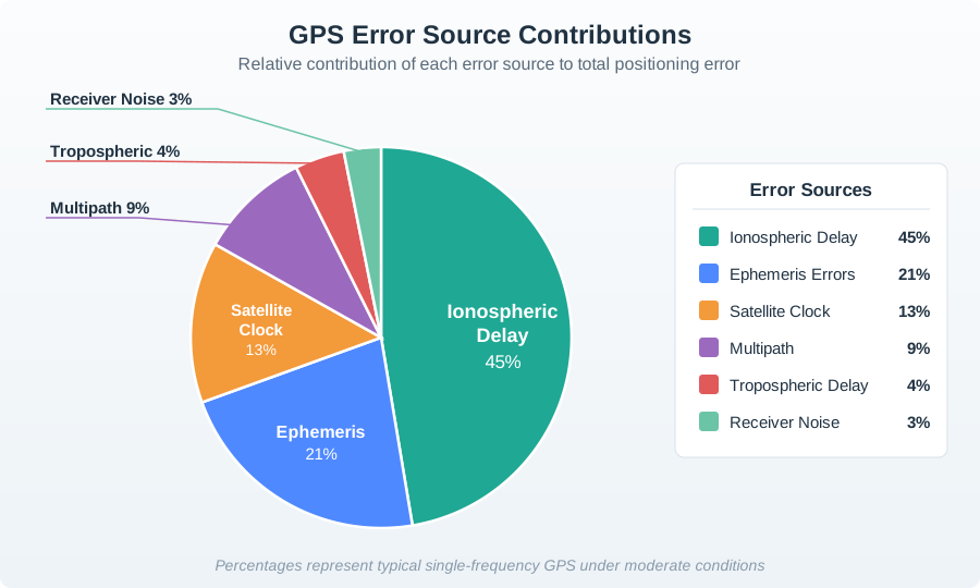
In Figure 23.2, compare slices as shares of UERE squared, not as metres that can be added directly. The ionospheric term dominates this stated example, ephemeris and clock follow, and local multipath or receiver noise contribute smaller variances. Figure 23.3 then reorders those same error families by where a transmitted signal encounters them.
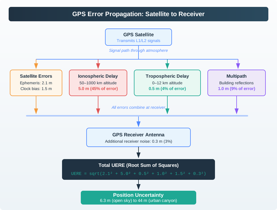
Follow Figure 23.3 from satellite clock and orbit knowledge, through ionospheric and tropospheric delay, to local reflections and receiver noise. The terms combine at the range estimate even though they originate in different places and vary on different timescales. That connection explains why a product needs both a calculated uncertainty and operational evidence about sky view, environment, corrections, and receiver state.
The ionosphere (50-1000 km altitude) is a layer of charged particles created by solar radiation. GPS signals travel through it, and the charged particles slow down the radio waves, making distances appear longer.
Why it’s variable:
Solar activity: During solar storms, ionospheric delay can spike to 10-15 meters (vs. 5m typical). Time of day: Peak ionization occurs at noon (sun overhead), minimum at night. Geographic location: Equatorial regions have 2-3× higher ionospheric activity than poles.
Mitigation:
Dual-frequency receivers: Military (L1 + L2) and modern smartphones (L1 + L5) measure two frequencies and calculate ionospheric delay directly. SBAS augmentation: WAAS (North America), EGNOS (Europe) broadcast ionospheric models. Single-frequency compromise: Civilian L1-only receivers can use the GPS broadcast Klobuchar model, which ESA Navipedia estimates reduces worldwide RMS ionospheric range error by about 50%. (ESA Navipedia)
23.9.2 Calculating Total GPS Uncertainty (UERE)
UERE (User Equivalent Range Error) is the root-sum-square (RSS) of all error sources, assuming they’re independent and random:
Follow the calculation from assumptions to interpretation. Each sigma term represents a one-sigma range-error contribution in metres; squaring prevents positive and negative deviations from cancelling, summing combines the independent variances, and the square root returns the result to metres. The resulting UERE is a ranging uncertainty, not the final horizontal position error. Satellite geometry and correlated or biased errors still matter, so carry those limits into the accuracy promise.
Plugging in typical values:
Adjust the error sources below to see how they affect total GPS uncertainty:
Try these scenarios:
- Open sky, good conditions: Set ionospheric = 3m, multipath = 0.3m, hypothetical HDOP = 1.5 → ~6.3m horizontal one-sigma uncertainty
- Urban canyon: Set ionospheric = 5m, multipath = 3.5m, hypothetical HDOP = 6.5 → ~44m horizontal one-sigma uncertainty
- Solar storm: Set ionospheric = 12m, hypothetical HDOP = 2.0 → ~25m horizontal one-sigma uncertainty
UERE (6 m in this example) summarizes one-sigma uncertainty in a satellite pseudorange. HDOP scales it for horizontal position uncertainty; PDOP for 3D position uncertainty. GDOP also includes receiver-clock uncertainty.
For one-sigma UERE:
- Good geometry (satellites spread across sky): hypothetical HDOP ≈ 1.5 → horizontal one-sigma uncertainty ≈ 9 meters
- Poor geometry (satellites clustered): hypothetical HDOP ≈ 3.0 → horizontal one-sigma uncertainty ≈ 18 meters
- Urban canyon (only overhead satellites visible): hypothetical HDOP ≈ 8.0 → horizontal one-sigma uncertainty ≈ 48 meters!
This is why GPS accuracy in downtown Manhattan (tall buildings) can degrade to 50+ meters, while open-sky rural areas achieve 3-5 meters.
Checkpoint: UERE and GDOP
You now know:
- UERE combines independent range errors with root-sum-square arithmetic.
- HDOP scales UERE for horizontal uncertainty, PDOP for 3D position uncertainty, and GDOP also includes receiver-clock uncertainty.
- Environment changes matter: open sky, urban canyon, and solar storm scenarios produce very different expected errors.
23.9.3 Accuracy from Phones to Agriculture
Once the math is visible, the design choice becomes a tiering decision.
Different IoT applications require different levels of positioning accuracy. Here’s how various technologies stack up:
| Technology | Typical Accuracy | Setup Requirements | Cost | Common IoT Use Cases |
|---|---|---|---|---|
| Smartphone GPS | 5-10 m | None (standalone) | Free | Navigation, asset tracking, geofencing |
| SBAS (WAAS/EGNOS) | 1-3 m | None (broadcast) | Free | Aviation, maritime navigation, outdoor robotics |
| DGPS | 0.5-1 m | Base station + radio link | $$$ (infrastructure) | Surveying, precision agriculture, autonomous vehicles |
| RTK GPS | 1-2 cm | Base station + continuous radio | $$$$ (equipment + subscription) | Precision farming (tractors), construction, drone surveying |
| PPP (Precise Point Positioning) | 5-10 cm | Internet connection | $$ (subscription) | Surveying, geophysical monitoring, autonomous driving |
The tiers in Figure 23.4 show why a location accuracy target has an infrastructure cost.
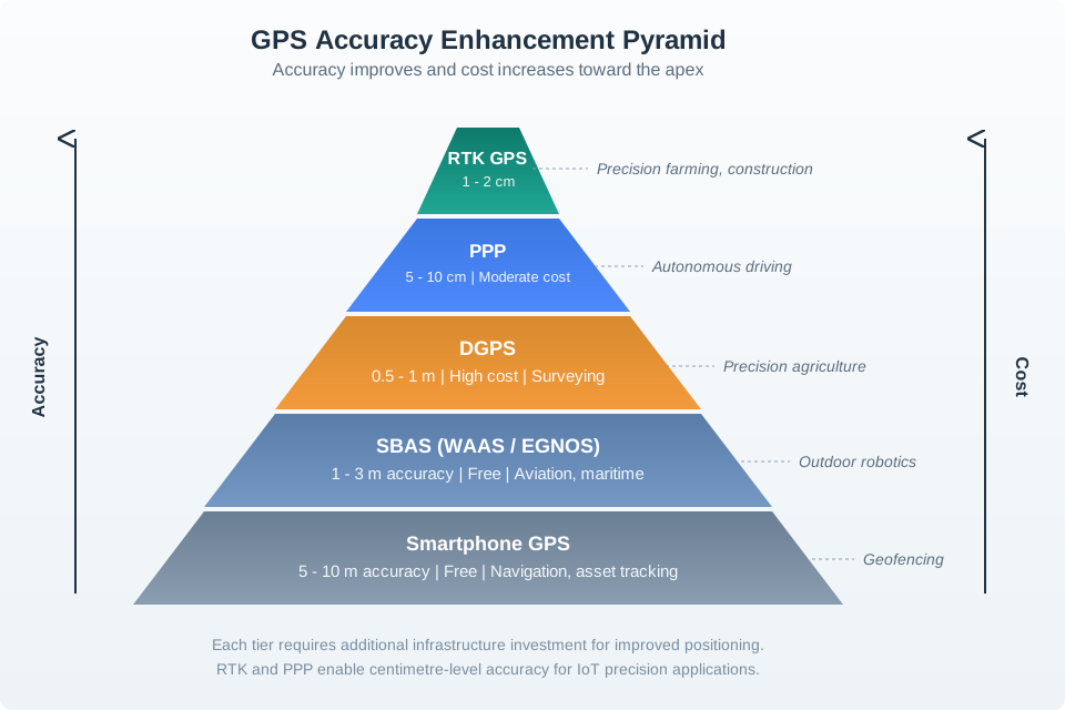
A phone GPS fix can support broad navigation or tracking, while augmentation and differential methods narrow the error under their stated conditions. PPP and RTK sit higher in precision and require more supporting service or equipment. The pyramid presents example ranges and uses, not a guarantee at every site. Choose the tier from the action’s tolerance and the resources available to maintain it. Then test real geometry, signal conditions, and update behavior before using a point estimate to trigger a product action.
Match accuracy to application requirements—don’t over-engineer!
| Application | Required Accuracy | Recommended Technology | Why |
|---|---|---|---|
| Asset tracking (shipping containers) | 10 m | Standard GPS | Just need to know “which warehouse” or “which city”—5-10m is overkill |
| Fleet management (delivery trucks) | 3 m | SBAS (WAAS) | Need to distinguish which side of street vehicle is on |
| Precision agriculture (autonomous tractor) | 2 cm | RTK GPS | Row spacing is 30-76 cm—need sub-decimeter accuracy to avoid crop damage |
| Drone surveying | 5 cm | PPP or RTK | Generating topographic maps requires centimeter-level vertical accuracy |
| Indoor warehouse | N/A | Wi-Fi/UWB | GPS doesn’t work indoors—need alternative positioning system |
Indoor Positioning Reality Check:
GPS signals are −130 dBm (extremely weak) outdoors. Building materials attenuate signals by 20-40 dB. Result: No GPS fix indoors in most buildings (concrete, steel). Solution: Use Wi-Fi fingerprinting (5-15m), BLE beacons (1-3m), or UWB (10-30cm) instead.
Myth 1: “GPS is always accurate to within 5 meters” Reality: 5-10m is open-sky accuracy. Urban canyons (tall buildings) can degrade accuracy to 50+ meters due to multipath and poor GDOP.
Myth 2: “More satellites = better accuracy” Reality: Satellite geometry matters more than count. 4 widely-spaced satellites (GDOP = 1.5) beat 8 clustered satellites (GDOP = 4.0).
Myth 3: “Differential GPS eliminates all errors” Reality: DGPS only corrects common-mode errors (ionosphere, satellite clock) that affect base and mobile identically. It doesn’t fix multipath (location-specific) or receiver noise.
Myth 4: “RTK gives 2cm accuracy everywhere” Reality: RTK requires continuous phase lock to satellites. Driving under bridges, trees, or tunnels breaks lock and accuracy degrades to standard GPS (5-10m) until lock is re-established.
Checkpoint: Accuracy Tiers
You now know:
- Standard GPS, SBAS, DGPS, RTK, PPP, Wi-Fi, BLE, and UWB solve different accuracy and environment problems.
- Over-engineering wastes power, infrastructure, and subscription budget.
- Under-engineering creates false arrivals, unsafe automation, and manual support work.
23.10 Continue to Part 2
This section: Continue to Part 2 — Continue with GPS Accuracy: Enhancement Decisions.
Continue with GPS Accuracy: Enhancement Decisions.
Find help
3 reviewed answers.
Where should I start in a module?
Open the module page from the sidebar to see its chapters in order. Use the module map to return to a topic you need.
Modules and pathsReviewed
What can I try when a project does not work?
Check the symptom, then work through the diagnostic steps. Keep the error message and the smallest example that reproduces it.
When you are stuckReviewed
How do interactive examples work?
Use the interactive guide to check how examples and simulations work before changing your project.
Interactive examples guideReviewed