18 Smart Contact Lenses: Power and Architecture
18.1 Start With the Decision
Researchers are testing tear-glucose lenses, but none described here replaces blood-glucose testing.
18.2 Route Overview
This is part 2 of 2. Review Smart Contact Lenses: Sensing Constraints for the preceding evidence.
18.3 Learning Objectives
- Trace power and data through a smart contact lens architecture.
- Compare AR and health-monitoring lenses by safety, sensing, and energy constraints.
18.4 Chapter Roadmap
- For Beginners: Smart Contact Lenses
- For Kids: Meet the Sensor Squad
- In 60 Seconds
- Smart Contact Lenses Overview
- Smart Lens Power and Data Flow
- Smart Contact Lens Architecture
- Tear-to-Blood Glucose Lag
- Putting Numbers to It
- AR Lenses vs. Health Monitoring Lenses
- Challenge-to-Solution Mapping
- Checkpoint: Power Math
- Continue to Part 2
18.5 For Beginners: Smart Contact Lenses
Smart contact lenses are ordinary-looking lenses you wear on your eyes, but with microscopic sensors and a tiny radio built in. Researchers are testing lenses that measure sugar in tears, but these cannot yet replace blood-glucose tests or finger pricks. Powering electronics next to the eye is hard, so some experimental lenses use energy sent by radio waves instead of a battery.
18.6 For Kids: Meet the Sensor Squad
Imagine a future invention: tiny computers on your eyes that might one day share health measurements with a doctor.
18.6.1 Magic Eye Lens Story
Eleven-year-old Amir has diabetes, which means his body has trouble managing sugar in his blood. Every day, he has to prick his finger to check his blood sugar — and it really hurts!
In this future story, Amir imagines a special pair of contact lenses that researchers might invent one day. They looked just like normal contacts, but inside lived a whole team of tiny sensor friends!
Glu the Glucose Detector was the star of the show. “In this future invention, I can sense a sugar-related signal in Amir’s tears!” she announced. “Tear readings do not yet reliably show current blood sugar, so Amir still follows his care team’s testing advice.” Next to her, Pressure Pete was carefully checking the inside of Amir’s eye. “Eye pressure normal! No signs of that sneaky condition called glaucoma.”
But how would all this information get to the doctor? That is where Radio Ray came in. He was so tiny he could fit on a speck of dust, but he could send invisible signals to Amir’s phone! “Message sent to the doctor’s computer!” Ray said proudly.
Meanwhile, Power Penny had the hardest job. “We cannot have a big battery next to someone’s eye — it would get too hot!” she explained. “Instead, I collect energy from invisible radio waves, like catching raindrops in a tiny bucket. It gives us just enough power to run everything!”
In this future story, Amir imagines his phone receiving a tear-sensor reading. Researchers have not shown that a lens can safely guide food or insulin decisions, so Amir keeps checking blood glucose as advised by his care team.
18.6.2 Key Words for Kids
| Word | What It Means |
|---|---|
| Smart Contact Lens | A tiny lens you wear on your eye that has invisible sensors and a radio inside |
| Glucose | Sugar in your blood and tears — too much or too little can make you sick |
| Biocompatible | Made from materials that are safe to put on your body without causing harm |
| Energy Harvesting | Collecting tiny amounts of energy from radio waves or light instead of using a battery |
| Tear Fluid | The thin layer of liquid that keeps your eyes moist — it contains health clues! |
18.6.3 Try This at Home!
The Tear Fluid Experiment:
- Peel an onion and notice your eyes watering — those are tears!
- Think about what might be dissolved in those tears (salt, proteins, sugar)
- Now imagine a sensor so small it could float in that thin tear layer
- That sensor would need to be thinner than a hair and softer than jelly
This is exactly the challenge engineers face: building electronics that are flexible, tiny, and safe enough to sit on your eye. Pretty amazing, right?
18.7 Learning Objectives
By the end of this section, you will be able to:
- Explain the sensor architecture of smart contact lenses including glucose, pressure, and biochemical sensing modalities
- Analyze power delivery challenges for on-eye electronics including RF harvesting, micro-fuel cells, and biofuel cells
- Evaluate biocompatibility requirements that constrain materials, form factor, and thermal dissipation
- Compare smart lens platforms from Google/Verily, Mojo Vision, and InWith for different application domains
- Calculate the IoT data pipeline from on-lens sensing through body-area relay to cloud analytics
- Design safe data-quality gates for lens readings before they appear in clinical, research, or wellness workflows
18.8 In 60 Seconds
This chapter covers smart contact lenses, explaining the core concepts, practical design decisions, and common pitfalls that IoT practitioners need to build effective, reliable connected systems.
18.9 Smart Contact Lenses Overview
Smart contact lenses represent a fascinating convergence of microelectronics, biomaterials, and data analytics, embodying the core principles of the Internet of Things (IoT) by seamlessly integrating sensing, processing, and communication capabilities directly onto the human body. These devices transcend the traditional function of vision correction, evolving into sophisticated platforms for health monitoring and augmented reality (AR).
18.10 Smart Lens Power and Data Flow
Step 1: Energy Harvesting Imagine a lens sitting on your eye with a tiny antenna etched into its edge (thinner than a human hair). When your phone or NFC reader gets within 5 cm, it emits radio waves at 13.56 MHz. The lens’s antenna captures these invisible waves and converts them into ~40 microwatts of electrical power - just enough to run the sensors and transmitter for a brief moment.
Step 2: Sensing Tear Glucose A glucose sensor (smaller than a grain of salt) sits between two layers of the soft lens material. Tear fluid naturally wicks through tiny channels to reach the sensor. An enzyme (glucose oxidase) reacts with glucose in the tears, producing a tiny electrical current proportional to glucose concentration. The sensor measures this current and converts it to a digital glucose reading.
Step 3: Processing and Storage A microcontroller (the “brain” of the lens, about 1 mm²) receives the glucose reading, adds a timestamp, and stores it in memory. Because power is limited, the lens only takes readings every 5 minutes and stores up to 6 readings (30 minutes of data) before needing to transmit.
Step 4: Wireless Transmission When you tap your phone near your eye (the NFC reader), the antenna not only powers the lens but also creates a communication channel. The lens transmits the stored glucose readings as a burst of data (~50 milliseconds). Your phone receives the data, processes it, and displays trends: “Glucose rising slowly - within target range.”
Step 5: Clinical Integration Your phone app uploads the glucose trends to the cloud (encrypted via HTTPS). The cloud analytics platform detects patterns (e.g., “glucose spikes after lunch every day”) and sends alerts to your diabetes management team. Your doctor reviews the data in your electronic health record via a FHIR API integration.
The challenge: All of this - sensing, processing, storing, transmitting - must happen using only 40 microwatts of harvested power and fit within a lens thinner than 200 micrometers (twice the thickness of a human hair) while remaining biocompatible for 12-24 hour wear on the eye.
Real-world analogy: It’s like building a complete weather station that fits on a postage stamp, runs on the energy from a flashlight beam, and reports data wirelessly - except it has to be safe enough to sit on your eyeball all day.
18.11 Smart Contact Lens Architecture
Understanding the layered architecture of a smart contact lens reveals why this is one of the most challenging IoT form factors to engineer. Every subsystem must operate within microwatt power budgets, millimeter-scale dimensions, and strict biocompatibility constraints.
Where does a lens get its power, and what does it actually send out? Figure 18.1 traces both directions across the same tiny antenna.
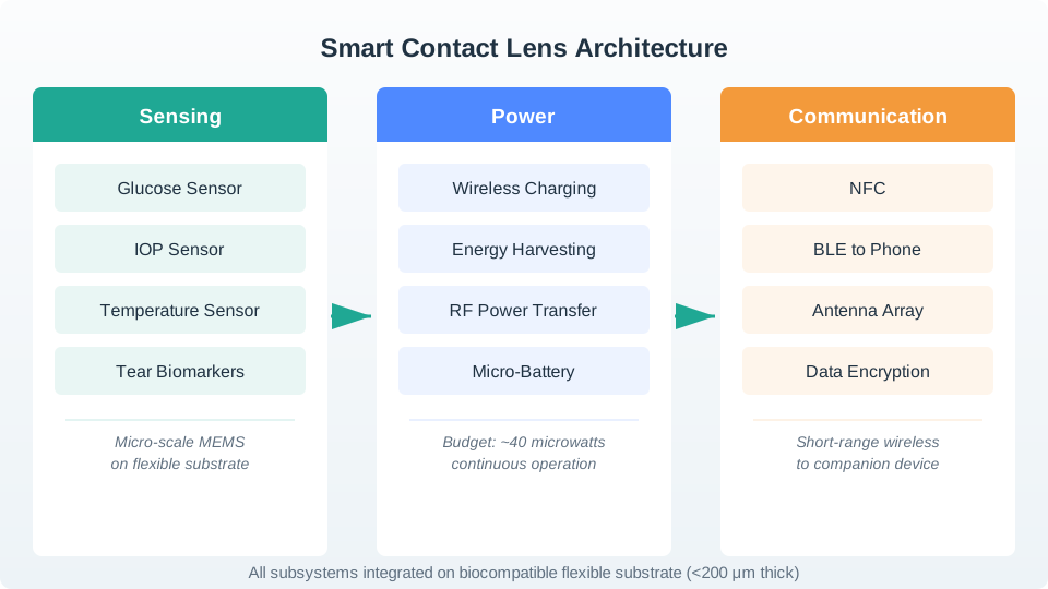
Follow the top row of Figure 18.1 first. A glucose sensor samples tear fluid every five minutes, a small controller stamps each reading with a time and holds about six of them, and the radio link sends the batch to a phone held within five centimetres. Now follow the arrow the other way. That same antenna turns the reader’s radio waves into roughly forty microwatts, and this is the whole budget the sensing and storage steps must live inside. The band across the bottom is the real limit: everything on the eye must stay thinner than a fifth of a millimetre and stay biocompatible. Those limits are why the phone shows trends and never a dosing instruction.
18.11.1 Smart Lens Data Pipeline
This alternative diagram emphasizes the data flow from physical measurement through to clinical decision-making, highlighting the latency and reliability requirements at each stage.
Inspect Figure 18.2 to place a smart lens reading within the wider route from patient device to clinical workflow.
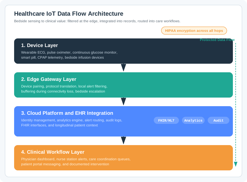
Start Figure 18.2 at the patient-device layer, where the lens joins other bedside or wearable sensors rather than becoming a clinical system by itself. The edge gateway handles local processing and any decision that cannot tolerate a cloud round trip. Cloud and EHR integration then give the measurement patient, unit, and care context through FHIR or HL7. The last branch routes alerts and trends to clinicians or the patient portal. Each boundary needs protected transport, identity, and audit evidence, while the clinical workflow remains responsible for acting on the result.
18.11.2 Sensing and Biometric Monitoring
Researchers are studying whether future validated smart contact lenses could measure glucose-related signals in tears and reduce some blood tests. No lens described here is validated for clinical glucose decisions. Integrated pressure sensors can also measure intraocular pressure, which may support glaucoma monitoring in an authorized clinical workflow. A lens can wirelessly transmit measurements to a paired device for review.
18.12 Tear-to-Blood Glucose Lag
Tear-glucose measurements are a research approach. Their relationship to blood glucose and the delay can vary with the person and tear collection, so no lens described here is validated for real-time insulin dosing or established as a clinical trend-alert tool.
18.12.1 Power Delivery Challenge
Power delivery is the single most constraining factor in smart contact lens design. Traditional batteries are too large, too heavy, and produce too much heat for on-eye use. Current approaches include:
Figure 18.3 shows the general harvesting chain a lens has to fit into, and where the lens design is forced to compromise.
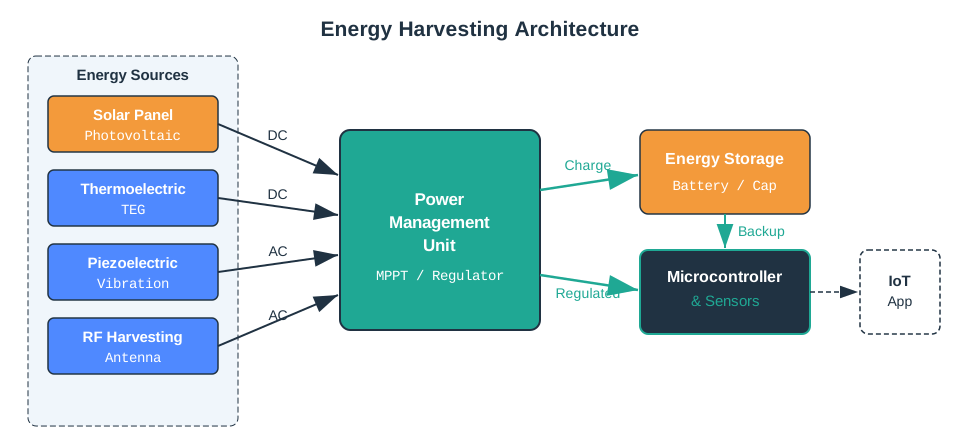
Read Figure 18.3 from left to right. Four ambient sources feed the chain, and the small labels matter: two deliver direct current and two deliver alternating current, so the input stage has to rectify as well as regulate. Everything then funnels into one power management unit, which is the part that keeps working even when a source does not. Its output charges a store, and the store, rather than the source, is what supplies the microcontroller and sensors at a steady voltage. For a lens, the store is the hard part. Anything large enough to smooth an intermittent source is exactly what cannot sit on an eye.
The power budget is extremely tight. A typical smart contact lens operates on a total power budget of 10-50 microwatts. For comparison, a Bluetooth Low Energy radio alone consumes approximately 10 mW during transmission — roughly 200-1000x more than the entire lens budget. This forces designers to use duty-cycled sensing (measure once every few minutes) and burst communication (store data, transmit in a short NFC burst when a reader is nearby).
18.13 Putting Numbers to It
Smart contact lenses face extreme power constraints. A duty-cycled glucose sensor that draws 2 µW for 150 ms every 5 minutes is active for only 0.05% of the interval. If the sleep draw is 0.2 µW, the average is about 0.201 µW: roughly 0.001 µW from sensing plus 0.2 µW from sleep. That is well within a 10-50 µW lens budget, but it also shows why sleep current dominates total energy even when active sensing draws ten times more power.
18.13.1 Augmented Reality and Visual Interfaces
Beyond health monitoring, smart contact lenses are poised to revolutionize human-computer interaction through AR. By incorporating micro-displays and optical components, these lenses can project digital information directly onto the wearer’s retina, overlaying virtual elements onto the real-world view. This capability can enhance navigation, provide instant access to contextual information, and support immersive applications such as gaming and remote collaboration. Eye vergence tracking, facilitated by integrated sensors, allows for intuitive control of on-lens interfaces based on the user’s natural eye movements. In addition, integrated cameras within the lens enable first-person image and video capture, transforming domains like documentation and real-time assistance.
18.14 AR Lenses vs. Health Monitoring Lenses
These are fundamentally different products. Health monitoring lenses (like Google/Verily’s glucose lens) require only microwatts and have no display. AR display lenses (like Mojo Vision’s platform) require milliwatts for the micro-LED array and represent a far more complex engineering challenge. Tear-glucose sensing remains research; it is not a validated clinical replacement for blood-glucose testing. AR lens availability also remains uncertain.
18.14.1 Security and Identification
The unique physiological characteristics of the iris make it a reliable biometric identifier. Smart contact lenses equipped with iris recognition capabilities can deliver secure authentication and access control, offering a discreet and convenient alternative to traditional methods such as passwords or external biometric devices.
18.14.2 Leading Smart Contact Lens Platforms
The following platforms illustrate how design choices vary by sensing goal, display ambition, and power strategy:
- Google/Verily: Experimental tear-glucose lens with wireless sensing; the glucose-sensing program was paused in 2018 because clinical measurements did not show a sufficiently consistent tear-to-blood glucose correlation for a medical device.
- Mojo Vision: AR display lens using a micro-LED array and eye tracking with a thin-film battery. Prototype demonstrated in 2022 before the company pivoted toward micro-LED display components.
- InWith: AR overlay lens using a flexible micro-display with hybrid solar and RF power. Still in R&D.
- IMEC/Ghent University: Intraocular pressure monitoring lens using a capacitive pressure sensor with RF harvesting. Clinical trials ongoing.
- POSTECH (Korea): Multi-analyte health lens measuring glucose, lactate, and pH using a biofuel cell. Currently a lab demonstration.
- Sensimed (Triggerfish): Glaucoma monitoring lens using a strain gauge with inductive coupling. The FDA permitted marketing of the device in 2016 for 24-hour monitoring of IOP patterns.
18.14.3 Challenges and Future Directions
Despite the significant promise of smart contact lenses, several challenges remain. Achieving reliable wireless power delivery and storage, ensuring biocompatibility and long-term comfort, and upholding data privacy standards are among the most pressing issues. Advances in micro-fabrication, energy harvesting, and low-power wireless communication will be vital to overcoming these hurdles.
18.15 Challenge-to-Solution Mapping
- Power scarcity: Use RF harvesting, aggressive duty cycling, burst NFC uploads, and ultra-low-leakage sleep modes.
- Biocompatibility and comfort: Build on oxygen-permeable hydrogels, flexible interconnects, and thermal budgets below roughly 2°C above body temperature.
- Measurement reliability: Compensate for tear-to-blood lag, temperature variation, and sensor drift with calibration plus trend-focused analytics.
- Privacy and clinical trust: Encrypt relay-to-cloud traffic, minimize retained identifiers, and integrate with audited clinical workflows instead of consumer-only dashboards.
- Manufacturing yield: Favor simpler layer stacks, reusable power-management blocks, and test points that verify the lens before sterile packaging.
18.15.1 Smart Lens Power Budget
Scenario: An IoT startup is designing a glucose-monitoring smart contact lens for diabetic patients. The lens must measure tear glucose every 5 minutes and transmit accumulated readings to the patient’s smartphone every 30 minutes via NFC.
Given:
- RF harvesting antenna: delivers 40 uW at 13.56 MHz when phone is within 5 cm
- Glucose biosensor: 2 uW during measurement (150 ms per reading)
- MCU (Cortex-M0+): 12 uW active, 0.5 uW sleep
- NFC transmitter: 30 uW for 50 ms burst (6 readings per burst)
- Temperature sensor: 1 uW for 10 ms per reading
- Target: 18-hour wear time, readings every 5 minutes
Steps:
-
Calculate number of readings per day:
- Readings per wear period: 18 hours x 60 min / 5 min = 216 readings
- NFC transmissions: 216 / 6 = 36 bursts
-
Calculate energy per glucose reading:
- Sensor: 2 uW x 0.15 s = 0.30 uJ
- MCU active (processing): 12 uW x 0.05 s = 0.60 uJ
- Temperature (compensation): 1 uW x 0.01 s = 0.01 uJ
- Total per reading: 0.91 uJ
-
Calculate energy per NFC burst:
- NFC transmitter: 30 uW x 0.05 s = 1.50 uJ
- MCU active (packaging data): 12 uW x 0.02 s = 0.24 uJ
- Total per burst: 1.74 uJ
-
Calculate daily energy budget:
- Sensing: 216 readings x 0.91 uJ = 196.6 uJ
- Transmission: 36 bursts x 1.74 uJ = 62.6 uJ
- MCU sleep: 0.5 uW x 18 hr x 3600 s = 32,400 uJ
- Total daily: 32,659 uJ = 32.7 mJ
-
Calculate required average power:
- Average power: 32,659 uJ / (18 x 3600 s) = 0.50 uW
- RF harvesting delivers 40 uW when active
- Need RF reader proximity for only: 32,659 uJ / 40 uW = 816 seconds = 13.6 minutes/day
Result: The lens requires only 0.50 uW average power, well within the 40 uW RF harvesting capability. The patient only needs their phone near their face for ~14 minutes total per day to fully power the lens. In practice, this happens naturally during phone calls, texting, or deliberate 30-second NFC taps every 30 minutes.
Key Insight: The dominant power consumer is not sensing or communication — it is the MCU sleep current (99.2% of total energy). Selecting an MCU with sub-100 nW deep sleep (such as the Ambiq Apollo series) could reduce total energy by 10x, enabling fully biofuel-cell-powered operation with zero phone interaction required.
 Checkpoint: Power Math
You know:
- An 18-hour wear period with readings every 5 minutes produces 216 readings and 36 six-reading NFC bursts.
- The chapter’s example totals 32,659 uJ, or 32.7 mJ, which averages to 0.50 uW across the wear period.
- Because MCU sleep contributes 32,400 uJ, or 99.2% of the total, sleep current is the main lever even though the RF harvest path can deliver 40 uW during reader proximity.
18.16 Continue to Part 2
Continue with Smart Contact Lenses: Power, Data, and Safety.
18.17 Continue Your Route
This final part closes the route from For Beginners: Smart Contact Lenses through Continue to Part 2. Return to Smart Contact Lenses: Sensing Constraints or continue from the applications module index.