LoRaWAN
End devices transmit to one or more gateways. Gateways forward packets to a network server that handles device state, duplicate suppression, routing, and downlink scheduling.
Gateway Ownership, Network Servers, Operator Models, and Cellular LPWAN Boundaries
LPWAN architecture, LoRaWAN gateways, LoRaWAN network server, Sigfox architecture, NB-IoT architecture, LTE-M architecture, gateway placement, device classes
An LPWAN architecture is the answer to a practical ownership question: who carries the message after the device wakes up? Sometimes your team owns the gateway and server path. Sometimes an operator owns the access network. Sometimes a cellular provider owns identity and coverage. This chapter starts by naming that boundary, because support, security, diagnostics, and release evidence all change when ownership changes.
Low-power wide-area networks are chosen for small, infrequent messages over long distances, but the radio technology is only part of the architecture. The design also decides who owns the access network, where security and routing decisions happen, how downlinks reach sleepy devices, and what evidence proves coverage at the site.
LoRaWAN commonly uses private, community, or operator gateways that forward radio packets to a network server. Ultra-narrowband LPWAN services use operator-managed base stations and backend delivery. Cellular LPWAN options such as NB-IoT and LTE-M use cellular access, subscriber identity, and mobile-network functions. Each model changes the boundary you must review.
For example, a water utility might place level sensors on hilltop tanks, pressure alarms in concrete pump rooms, and valve controllers beside public roads. A private LoRaWAN design can work well when the team can place gateways, secure backhaul, and operate the network-server boundary. An operator LPWAN design shifts access responsibility outside the utility, so the review must focus on provider coverage, service continuity, and integration diagnostics. A cellular LPWAN design changes the identity, plan, roaming, and power-mode questions. The architecture decision is therefore not "which radio reaches farthest"; it is which ownership model can prove the actual path for each device group.
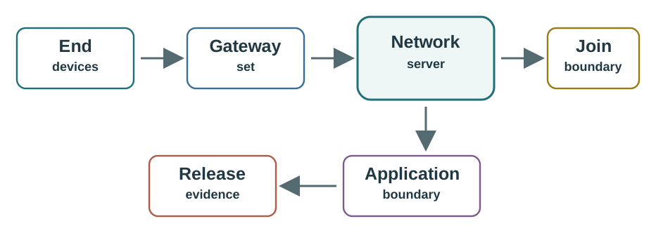
End devices transmit to one or more gateways. Gateways forward packets to a network server that handles device state, duplicate suppression, routing, and downlink scheduling.
Devices use operator-managed radio access and backend services. The customer reviews integration, coverage, identity, payload limits, and continuity risk.
NB-IoT and LTE-M use cellular radio access and mobile-network functions. SIM or eSIM identity, carrier coverage, roaming, and service plan ownership become design inputs.
Coverage claims need site evidence. Buildings, terrain, antenna height, gateway backhaul, interference, regional rules, and indoor placement shape the real result.
A practical LPWAN architecture record starts with roles. In LoRaWAN, gateways normally forward packets and metadata; the network server owns device-session state, duplicate suppression, adaptive data-rate decisions, and downlink scheduling. In operator-managed LPWAN and cellular LPWAN, more of the access and core-network behavior sits outside the project team.
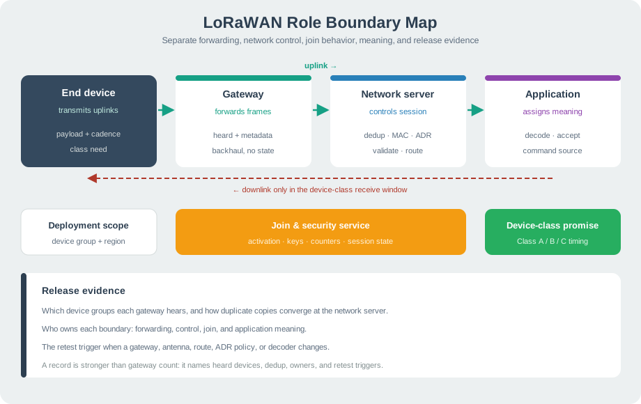
For each candidate, record the workload, message size pattern, downlink requirement, mobility assumption, ownership model, access-network boundary, application integration, coverage evidence, failure mode, and retest trigger. A small pilot should prove the path in the places where devices will actually live.
Use the record to prevent a common deployment mistake: treating one successful field reading as architecture approval. A gateway on a temporary mast, a hosted server trial account, and a lab SIM can all make a prototype look finished while leaving the production owner unclear. The practitioner record should say who will replace gateway backhaul after a storm, who can inspect denied joins, who receives operator outage notices, who rotates device credentials, and who authorizes a downlink retry when the first command misses the receive window. Those owners are part of the architecture, not operational paperwork added later.
LPWAN architecture decisions become risky when a design promises downlink behavior, mobility, or service continuity without proving the mechanism. A battery-first LoRaWAN Class A device only opens receive opportunities after an uplink. Class B and Class C can support different downlink timing, but they change power and operational assumptions. Cellular LPWAN power-saving modes and operator paging behavior also need workload-specific evidence.
The release gate should test the exact timing path, not just the fact that a packet eventually arrives. In a LoRaWAN design, that means logging the uplink that opened the receive window, the network-server scheduling decision, the gateway selected for the downlink, and the observed device response. In a cellular LPWAN design, it means proving attach state, paging or power-saving behavior, operator reachability, application retry behavior, and the cost of waking the device more often. In an operator-managed ultra-narrowband design, it means checking the provider callback, duplicate handling, delayed delivery, and support evidence. Each family can be valid, but each family needs its own proof chain.
LoRaWAN gateway placement evidence does not prove cellular coverage, and cellular attach success does not prove LoRaWAN downlink scheduling. Keep the architecture family, ownership boundary, and release evidence matched to the actual candidate.
A good under-the-hood review also records the failure test. Remove one gateway from the LoRaWAN pilot and check whether another gateway hears the uplink, whether the network server suppresses duplicates correctly, and whether a downlink still reaches the device class promised in the design. For cellular LPWAN, move a test device through the weakest indoor location and compare attach, retry, and battery behavior against the service plan. For operator-managed LPWAN, force a callback failure and confirm that missing or delayed messages are visible to the team that owns incident response. These tests turn architecture diagrams into release evidence.
LPWAN architecture choices are ownership and evidence decisions. LoRaWAN, operator-managed LPWAN, and cellular LPWAN can all serve low-power long-range workloads, but they put access, identity, routing, coverage, downlink, and operations responsibilities in different places.
The safest review path is to record the workload, ownership model, network boundary, device behavior, coverage evidence, application integration, and retest trigger before treating a technology choice as deployable.
Do not approve an LPWAN architecture from radio range alone. Approve the boundary: who owns the access path, where network decisions happen, how downlinks work, what site evidence proves coverage, and what change reopens the design.