PROFINET
Review controller-device roles, device descriptions, cyclic IO, alarms, diagnostics, topology, and conformance evidence.
A protocol is a shared set of rules for sending data. A gateway is a device or service that passes data between unlike systems. Firmware means software stored on a device. Define these jobs before comparing product names.
Picture a belt that must stop before a box falls. Its control message has a hard time limit. A dashboard update does not. Both may share Ethernet, but a fast link alone does not prove that the belt will stop on time.
Start with the motion and the harm if it is late. Name the controller, drive, sensor, and wires in the real machine. Measure the time taken by the control loop. Then test alarms, faults, part swaps, and the path that sends slower data to a dashboard.
Industrial Ethernet is a family of ways to use Ethernet for machine work. PROFINET, EtherCAT, EtherNet/IP, and Time-Sensitive Networking (TSN) make different choices about timing and control. Choose from proof on the real site, not from a speed claim.
This Overview treats each traffic type as either time-critical control or slower support data. A real line may have more timing groups and safety rules. The later levels show exact cycle, sync, topology, and gateway records. Use them before a release claim.
Run one clear test. Mark the start of a control cycle. Mark when the drive acts. Repeat it while other data crosses the link. Keep the worst time, not just the best one. Then break one cable or replace one drive and record how the line reports the fault.
Keep safety apart from normal control. A safe stop needs its own design and proof. A fast normal message must not be used as proof of a safe stop. Name the rule and the team that owns each path.
Finish at the gateway. Check units, names, times, and fault state on both sides. A dashboard value is useful only when its source and age are still clear.
Save the test setup with the result. A time claim without the real parts, load, and line shape cannot be checked again.
Imagine a machine cell where one Ethernet frame carries a drive update, another carries diagnostics, and another feeds a dashboard through an integration boundary. Calling the whole design “fast Ethernet” misses the review question: which traffic has a control consequence, and what evidence proves it behaves in the real topology?
Industrial Ethernet choices should start with that control story. Name the cycle time, device roles, topology, diagnostics, gateway handoff, and owner who will recheck the evidence when hardware, firmware, or the line layout changes.
Industrial Ethernet is not a single protocol. It is a family of Ethernet-based control and integration approaches that make different promises about timing, topology, device roles, diagnostics, configuration, and gateway boundaries.
The review question is not "which protocol is fastest?" The useful question is "which control behavior is proven for this machine, device set, topology, maintenance model, and integration boundary?"
For example, a packaging cell might need a 4 ms update for servo handoff, 20 ms status updates for remote IO, and dashboard publishing every second. The protocol decision should not collapse those into one speed number. The release record should show which traffic is cyclic control, which traffic is diagnostics, which data crosses the OPC UA or MQTT boundary, and what happens when a drive is replaced during maintenance. If PROFINET, EtherCAT, EtherNet/IP, or TSN is selected, the reviewer should be able to point to the timing trace, device role map, topology drawing, diagnostic path, gateway rule, and owner who will recheck the claim after firmware, device, or line-layout changes.
If you only need the intuition, this layer is enough: choose Industrial Ethernet by evidence. Start with the machine timing need, then prove topology, device support, diagnostics, safety boundary, gateway boundary, and operations ownership.
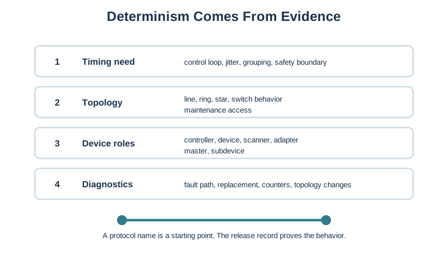
Before carrying Determinism is a release claim, not a protocol slogan. The record must show timing, topology, role, synchronization, diagnostics, and gateway evidence into the “Timing need” design record, view Figure 6.1. It makes “Timing need” and “control loop, jitter, grouping, safety boundary” separate, inspectable parts of the “timing need”–“control loop, jitter, grouping, safety boundary” decision.
Notice “Timing need” on Figure 6.1 as the condition under review. “control loop, jitter, grouping, safety boundary” marks the adjacent responsibility, while “Topology” leads to “line, ring, star, switch behavior”. Together they explain Determinism is a release claim, not a protocol slogan. The record must show timing, topology, role, synchronization, diagnostics, and gateway evidence; preserve that division when documenting the “timing need”–“control loop, jitter, grouping, safety boundary” decision.
Review controller-device roles, device descriptions, cyclic IO, alarms, diagnostics, topology, and conformance evidence.
Review frame path, process image mapping, working counters, distributed clocks where required, and topology recovery behavior.
Review CIP objects, services, assemblies, explicit or implicit messaging, multicast behavior, and gateway mapping.
Review the selected IEEE 802.1 tools, profile, schedules, bridges, end stations, configuration owner, and change process.
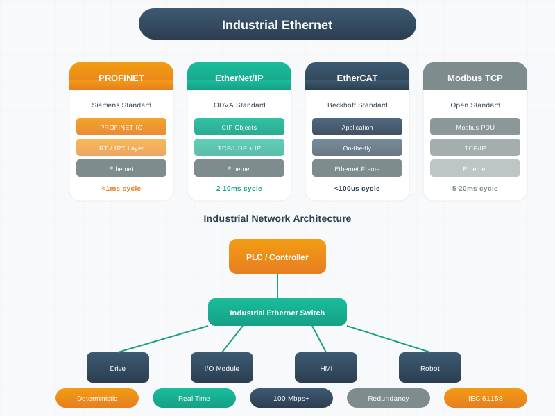
Inspect Figure 6.2 with one question from the “siemens standard”–“profinet io” decision: how does “Siemens Standard” constrain “PROFINET IO”? The answer supports Industrial Ethernet families differ by role model, scheduling assumptions, topology behavior, tooling, and where gateway integration belongs.
Notice “Siemens Standard” on Figure 6.2 as the condition under review. “PROFINET IO” marks the adjacent responsibility, while “RT / IRT Layer” leads to “Ethernet”. Together they explain Industrial Ethernet families differ by role model, scheduling assumptions, topology behavior, tooling, and where gateway integration belongs; preserve that division when documenting the “siemens standard”–“profinet io” decision.
A durable Industrial Ethernet decision separates control-network behavior from supervisory integration. The same machine may use an Industrial Ethernet family for cyclic control, OPC UA for information modeling, MQTT for event distribution, and a historian path for long-term review. The release record keeps those boundaries explicit.
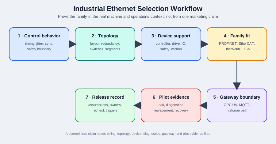
The next choice in the “prove the family in the real machine and operations context, not from one marketing claim”–“1 · control behavior” decision depends on “timing, jitter, sync”, a boundary shown in Figure 6.3. Inspect “Prove the family in the real machine and operations context, not from one marketing claim”, then set it against “1 · Control behavior”, before judging Selection workflow: define control behavior, prove topology and devices, place gateways, run pilot evidence, and write the release record.
Map the responsibilities in Figure 6.3: “Prove the family in the real machine and operations context, not from one marketing claim” comes first, “1 · Control behavior” follows, and “timing, jitter, sync” resolves at “safety boundary”. This division makes Selection workflow: define control behavior, prove topology and devices, place gateways, run pilot evidence, and write the release record inspectable and tells the the “prove the family in the real machine and operations context, not from one marketing claim”–“1 · control behavior” decision record what to preserve after release.
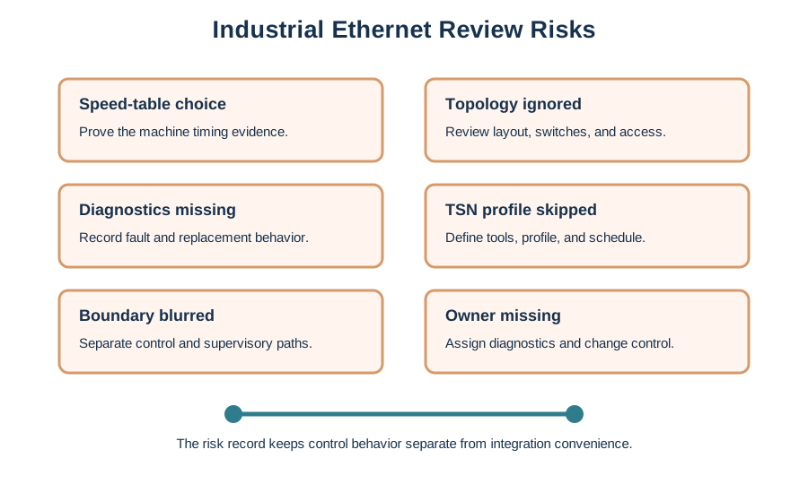
The next choice in the “speed-table choice”–“prove the machine timing evidence” decision depends on “Topology ignored”, a boundary shown in Figure 6.4. Inspect “Speed-table choice”, then set it against “Prove the machine timing evidence”, before judging Review risks to catch before release: speed-table selection, ignored topology, missing diagnostics, skipped TSN profile, blurred gateway boundary, and missing owner.
Trace Figure 6.4 by asking what “Speed-table choice” establishes and what “Prove the machine timing evidence” changes. Check “Topology ignored” next, ending at “Review layout, switches, and access”. That progression is the mechanism behind Review risks to catch before release: speed-table selection, ignored topology, missing diagnostics, skipped TSN profile, blurred gateway boundary, and missing owner and the evidence order needed for the “speed-table choice”–“prove the machine timing evidence” decision.
Industrial Ethernet families are reviewed through different internal records. A good design does not flatten PROFINET, EtherCAT, EtherNet/IP, and TSN into a single ranking table. It records the specific behavior each family must prove in the deployed topology.
The evidence buckets differ because the mechanisms differ. A PROFINET review starts with roles, device description, cyclic data, and alarms. An EtherCAT review starts with the frame path, process image, working counter, and clock behavior. An EtherNet/IP review starts with CIP objects, assemblies, services, and connection behavior. A TSN review starts with selected IEEE 802.1 tools, profiles, schedules, bridge support, and configuration ownership. Mixing those records hides the real release risk.
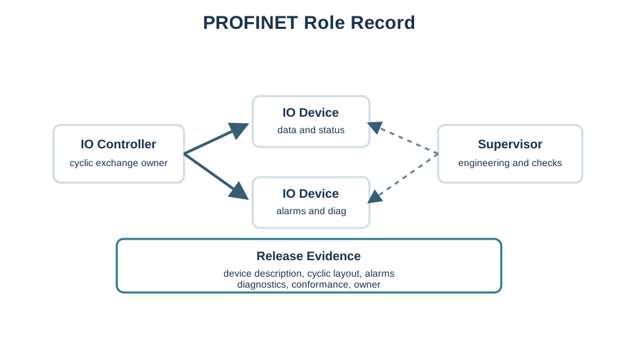
To ground the “io controller”–“cyclic exchange owner” decision through “IO Device” in visible evidence about “IO Controller”, inspect Figure 6.5. Its named elements “IO Controller” and “cyclic exchange owner” frame the claim that PROFINET review centers on controller-device relationships, device descriptions, cyclic data, alarms, diagnostics, topology, and conformance evidence.
On Figure 6.5, inspect “IO Controller” before “cyclic exchange owner”. The subsequent hand-off from “IO Device” to “data and status” explains PROFINET review centers on controller-device relationships, device descriptions, cyclic data, alarms, diagnostics, topology, and conformance evidence. Carry that sequence into the “io controller”–“cyclic exchange owner” decision so “IO Controller” evidence, “cyclic exchange owner” decision, and “data and status” recheck remain distinguishable.
For PROFINET, document the IO Controller, IO Device, and IO Supervisor roles; module or submodule configuration; cyclic data layout; alarm and diagnostic behavior; topology assumptions; and change procedure for replacement or firmware drift.
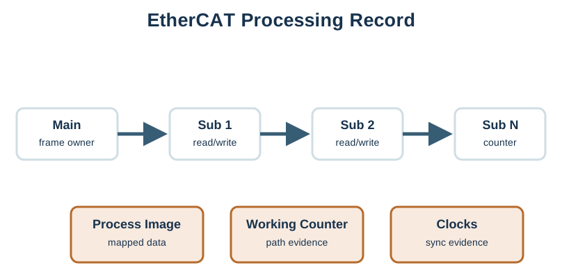
The claim that EtherCAT review centers on the ordered frame path, process-image ownership, expected working counter, distributed-clock proof, topology diagnostics, and recovery evidence needs “Prove frame path, process image, working counter, clocks, topology, and recovery behavior” as a concrete check beside “Processing-on-the-fly frame path”. Inspect Figure 6.6 before continuing the “prove frame path, process image, working counter, clocks, topology, and recovery behavior”–“processing-on-the-fly frame path” decision, especially “Prove frame path, process image, working counter, clocks, topology, and recovery behavior” beside “Processing-on-the-fly frame path”.
Notice “Prove frame path, process image, working counter, clocks, topology, and recovery behavior” on Figure 6.6 as the condition under review. “Processing-on-the-fly frame path” marks the adjacent responsibility, while “Main device” leads to “owns frame cycle”. Together they explain EtherCAT review centers on the ordered frame path, process-image ownership, expected working counter, distributed-clock proof, topology diagnostics, and recovery evidence; preserve that division when documenting the “prove frame path, process image, working counter, clocks, topology, and recovery behavior”–“processing-on-the-fly frame path” decision.
For EtherCAT, document main device and subdevice order, process image ownership, expected working-counter behavior, clock synchronization evidence where required, cable or port diagnostics, and recovery when one segment is unavailable.
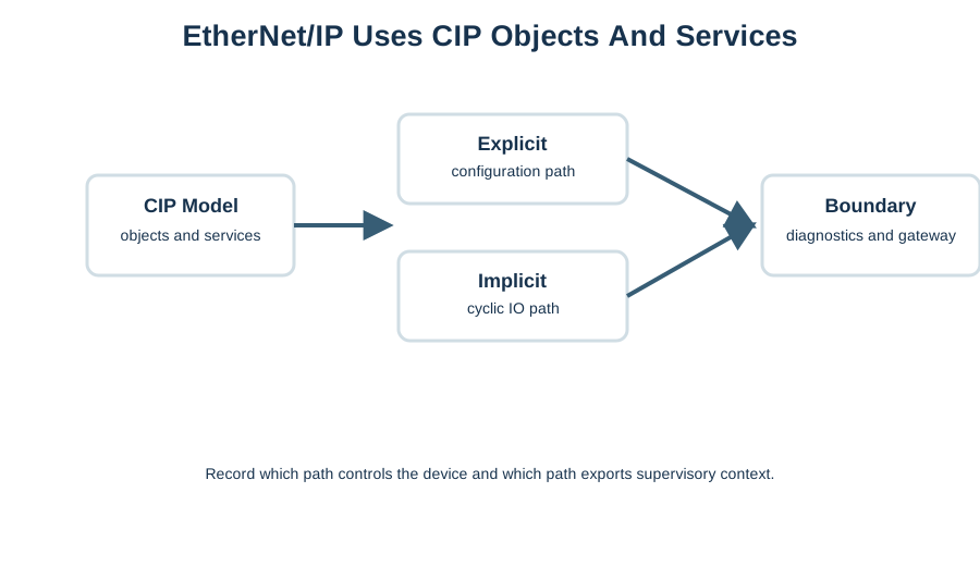
To ground the “cip model”–“objects” decision through “assemblies” in visible evidence about “CIP Model”, inspect Figure 6.7. Its named elements “CIP Model” and “objects” frame the claim that EtherNet/IP brings CIP object, service, and connection concepts onto Ethernet/IP networks; gateway mapping should preserve context and authority.
Follow Figure 6.7 through four named stops: “CIP Model”, “objects”, “assemblies”, and “services”. Their order turns EtherNet/IP brings CIP object, service, and connection concepts onto Ethernet/IP networks; gateway mapping should preserve context and authority into a reviewable path. In the “cip model”–“objects” decision, use the same stops to locate evidence and assign the recheck.
For EtherNet/IP, document CIP objects, services, assemblies, explicit or implicit messaging purpose, multicast handling, diagnostics, and gateway mappings into OPC UA, MQTT, historians, or application APIs.
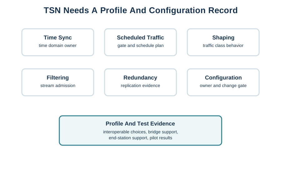
A release decision about the “time sync”–“time domain owner” decision needs “Scheduled Traffic”, not a slogan. Inspect Figure 6.8 through “Time Sync” and “time domain owner” to check this claim: TSN is a toolbox. The design must state which tools, profile, schedules, bridges, end stations, and configuration owner are released.
Inspect “Time Sync” against “time domain owner” on Figure 6.8, then test the link between “Scheduled Traffic” and “gate and schedule plan”. The two comparisons clarify TSN is a toolbox. The design must state which tools, profile, schedules, bridges, end stations, and configuration owner are released. They also keep “Time Sync” in the running decision about the “time sync”–“time domain owner” decision, tied to labelled evidence.
For TSN, document time synchronization ownership, scheduled traffic or shaping choices, profile or application standard, bridge and end-station capability, configuration ownership, and separation between control traffic and ordinary IT traffic.
Boundary rule: OPC UA, MQTT, dashboards, and historians can carry valuable supervisory context, but they should not be treated as proof that the deterministic control network is correctly released.
Industrial Ethernet selection is a control-system evidence problem. PROFINET, EtherCAT, EtherNet/IP, and TSN each bring different assumptions about roles, timing behavior, topology, diagnostics, configuration, and integration boundaries. A defensible release proves machine timing, device support, topology behavior, diagnostics, safety boundaries, gateway mapping, and operations ownership before treating a protocol name as a decision.
Industrial Ethernet choices must respect deterministic timing, topology, diagnostics, safety zones, gateway boundaries, and plant ownership before connecting to IoT platforms.
Place Industrial Ethernet among fieldbus, brownfield, supervisory, and gateway protocol families.
Use the broader selection workflow for requirement gates, evidence matrices, and recheck triggers.
Connect control-network data to information-model and supervisory integration boundaries.
Compare deterministic control-network evidence with register-oriented brownfield integration.