Coils
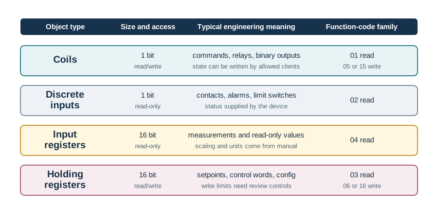
Single-bit read/write outputs such as run commands, relay outputs, resets, or binary actuator states.
Data Model, Function Codes, Serial Framing, TCP Encapsulation, Gateways, Troubleshooting, and Security Review
Modbus, Modbus RTU, Modbus TCP, register map, function codes, industrial protocol
Imagine a gateway reading “40017” from a heat meter and publishing it as supply temperature. The useful question is not whether Modbus returned bytes. The useful question is whether everyone agrees on the object family, wire address, scaling, byte order, permission, and physical check that prove the number is the right one.
Modbus works best when the register contract is visible. Start with one value a system will trust, then write down how the request, response, conversion, gateway path, and safety boundary preserve its meaning.
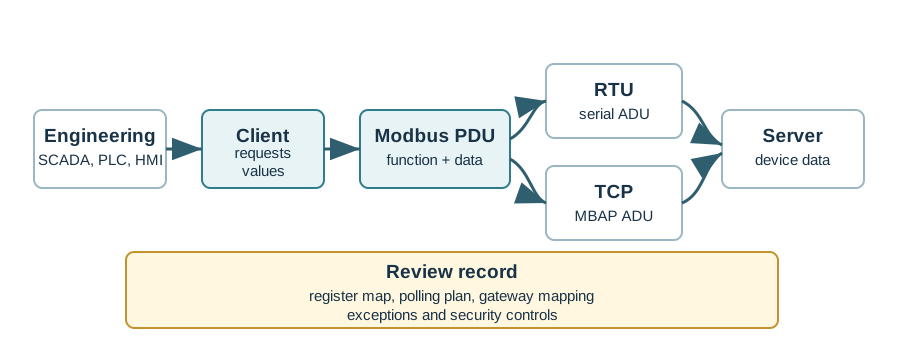
Modbus is a compact industrial request/response protocol for reading and writing device state. Its stable idea is not a rich device model; it is a client asking a server for coils, discrete inputs, input registers, or holding registers. The engineering meaning comes from the device register map, not from the protocol alone.
That separation is useful and dangerous. It makes Modbus easy to bridge across serial and TCP paths, but it also means a dashboard value is only trustworthy when the object type, address convention, scaling, signedness, byte order, word order, write permission, and polling plan are recorded together.
For example, a heat-meter manual might label a supply temperature as holding register 40017, scale it by 0.1 degrees, and store a 32-bit value across two adjacent 16-bit registers. One client library may expect the human reference number, another may expect zero-based protocol address 16, and a gateway may pass only the function code plus address onward to a serial device. The register contract is the note that keeps those views aligned: it states the documented label, the object family, the address sent on the wire, the conversion rule, and the evidence that a known physical value decodes correctly.
If you only remember one rule, remember this: Modbus does not explain what a value means. The register map and integration record do.
Single-bit read/write outputs such as run commands, relay outputs, resets, or binary actuator states.
Single-bit read-only inputs such as contact states, alarm bits, limit switches, and status points.
Read-only numeric values, commonly used for measurements, meter readings, and device-reported state.
Read/write numeric values, commonly used for setpoints, configuration, control words, and some status maps.
A useful Modbus integration record lets another engineer reproduce the connection without guessing. It identifies the device, each value, the object family, the protocol address expected by the client or gateway, the engineering unit, the scaling rule, byte and word order, read/write permission, and the expected polling behavior.
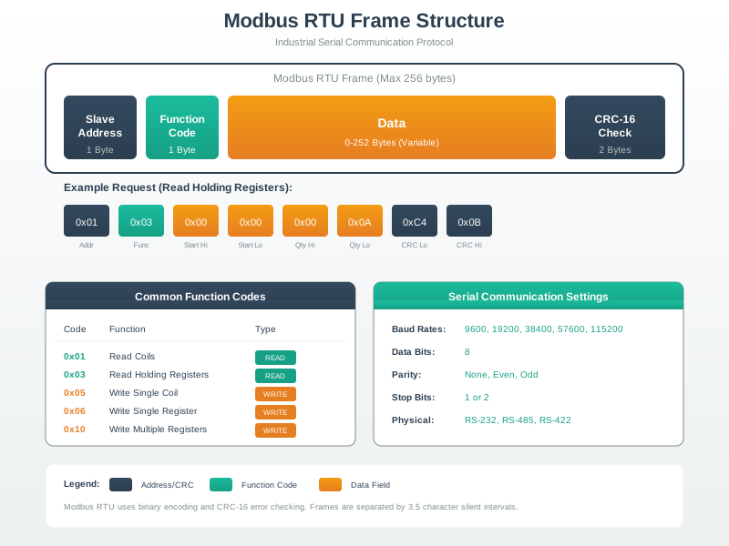
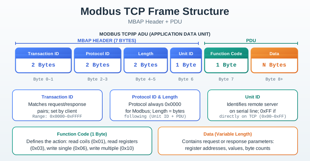
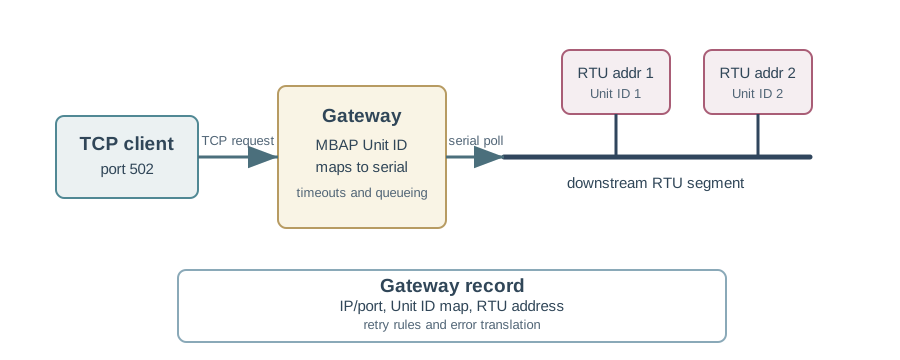
The record also explains the transport path. Modbus RTU carries requests over a serial segment with device addresses, timing boundaries, and frame error checks. Modbus TCP carries the same application operation through a TCP connection with an application header. Gateways are the place where many mistakes hide because they translate an Ethernet request into a downstream serial request.
In a small pump-skid integration, the record should make each assumption testable before the polling loop is left unattended. Start with three or four points that operators can verify from the local panel: run status, commanded start, measured pressure, and a writable setpoint if writes are allowed. Capture the raw register values, decoded engineering values, function codes used, exception responses if a write is blocked, and the exact gateway route. Only then scale up the poll list, because a fast scan of badly mapped registers produces confident but misleading telemetry.
Good Modbus troubleshooting separates symptoms before changing configuration. A timeout, a serial frame error, an exception response, and a wrong engineering value point to different parts of the system. Treating every symptom as a generic network failure usually adds retries while leaving the real defect in the register map, gateway boundary, or security envelope.
Classic Modbus also lacks built-in user authentication, authorization, and encryption. That does not automatically force replacement, but it does require an explicit security boundary: allowed clients, blocked write paths where possible, controlled remote access, monitoring for unexpected function codes, and a documented plan for secure gateways or protocol alternatives when exposure or risk changes.
A useful triage pattern is to preserve the first failing request and classify it before tuning. No bytes back suggests reachability, serial settings, address, timeout, or gateway routing. A Modbus exception response means the server answered but rejected the operation, so function code, address range, permission, or device mode is the next evidence. A plausible response with an impossible value means decoding work: offset convention, scaling, signed interpretation, endian order, stale point mapping, or a wrong adjacent register. Keeping those buckets separate prevents a security or data-quality issue from being hidden behind more retries.
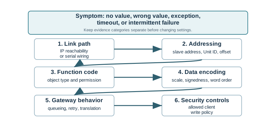
Check physical path, IP reachability, serial settings, device address, gateway route, timeout, and retry behavior.
Compare function code, object type, address, value range, write permission, and device mode against the register map.
Review offset notation, scaling, decimal position, signedness, byte order, word order, and engineering units.
Review allowed clients, firewall rules, write-code blocking, change logs, remote-access path, and device mode.
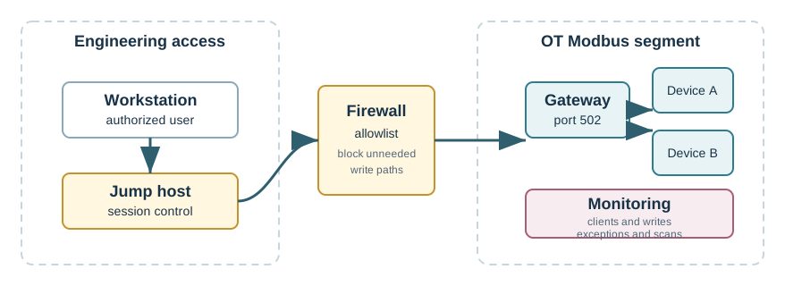
Modbus is useful because it is small and predictable, but that simplicity shifts responsibility into engineering records. The protocol defines object families, function operations, and transport mappings. The device register map defines meaning, scaling, write safety, and decoding. RTU, TCP, and gateway paths all need different evidence, and classic Modbus deployments need an explicit security envelope before values are exposed upstream.
Modbus integration succeeds when the register map, address convention, encoding rule, transport path, gateway mapping, troubleshooting evidence, and security boundary are reviewed as one contract.
Compare Modbus with richer industrial protocol families and the IT/OT boundaries around them.
Use selection evidence to decide when a simple register protocol is enough and when another pattern fits better.
Study how information models and built-in security change industrial integration design.
Review deterministic Ethernet choices when cyclic control behavior matters more than register polling.