15 Relays and Solenoids: Switching Choice and Safety
More
Depth: Practitioner
Progress saves as you read. Mark sections complete as you go; your progress appears in the sidebar.
15.1 Start With the Decision
This section: Start With the Decision — A relay uses moving contacts to switch a load.
A relay uses moving contacts to switch a load. An SSR, or solid-state relay, switches it without moving contacts. A MOSFET is a transistor used as an electronic switch. These three switches differ in speed, loss, isolation, and safe state. Check those needs before choosing one.
15.2 Route Overview
This section: Route Overview — This is part 2 of 2.
This is part 2 of 2. Review Relays and Solenoids: Drivers and Protection for the preceding evidence.
15.3 Learning Objectives
This section: Learning Objectives
- Compare relay, SSR, and MOSFET limits.
- Check contact stress, isolation, high voltage, and default state.
15.4 Chapter Roadmap
This section: Chapter Roadmap
- Complete Decision Framework: Relay vs SSR vs MOSFET
- Relay Arc Erosion in Inductive Loads
- Safety Considerations
- High Voltage Safety
- Concept Check: Relay Safety
- For Kids: Meet the Actuator Crew!
- Checkpoint: Failure Modes
- Deep Dive: Coil Drivers, Contact Stress, and Kickback Paths
- Summary
- Key Takeaway
- Knowledge Check
- Quiz: Relays and Solenoids
- Concept Relationships
- See Also
- Common Pitfalls
- 1. Driving Relay Coil Directly from GPIO
- 2. Omitting Flyback Diode on Relay or Solenoid Driver
- 3. Connecting SSR Output to DC Load Without Checking SSR Type
- 4. Check NC Relay Default State
- What’s Next
- Label the Diagram
- Code Challenge
| Selection Criteria | Mechanical Relay | Solid-State Relay (SSR) | MOSFET Switch |
|---|---|---|---|
| Switching speed | 5-15 ms (mechanical delay) | 1-100 µs (zero-cross: half-cycle delay) | 10-100 ns (instant) |
| On-state voltage drop | 0.50 V at the row’s assumed 50 mΩ and 10 A; use actual contact-resistance data | 1.0-1.6 V (SCR/TRIAC forward drop) | 10-200 mV (Rds(on) dependent) |
| Off-state leakage | Zero (galvanic isolation) | 0.1-1 mA (semiconductor leakage) | <1 µA (negligible) |
| Electrical isolation | Full galvanic (>1 kV typical) | Optocoupler (2.5-4 kV) | None (requires isolated gate drive for high-side) |
| Switching frequency max | 1-5 Hz (contact bounce, mechanical wear) | 60 Hz (AC zero-cross) to 1 kHz (DC) | 100 kHz+ (limited by gate drive and switching loss) |
| Power dissipation (10A load) | 5 W in contacts at the row’s assumed 50 mΩ, plus separate coil power; use actual contact resistance | 10-16 W at a 1.0-1.6 V on-state drop; check heatsink rating | 0.2-1 W for 2-10 mΩ on-resistance, before switching loss |
| Audible noise | Loud click on every operation | Silent | Silent |
| Mechanical lifespan | 10⁵-10⁷ cycles (contact wear) | Unlimited (no moving parts) | Unlimited (no moving parts) |
| Failure mode | Contacts weld closed OR burn open | Usually fails short (conducting) | Usually fails short (Drain-Source) |
| Relative cost | Low to moderate | Moderate to high | Low for DC switching |
| PWM suitability | No (arcing at contacts) | Limited (zero-cross SSR: max 60 Hz; DC SSR: yes) | Excellent (high-frequency PWM) |
| Typical IoT application | HVAC control, irrigation valves, lights (infrequent switching) | Heater control (PWM or proportional), high-cycle lighting | Motor speed control, LED dimming, DC load switching |
Decision tree for IoT actuator control:
-
Switching AC mains (120V/240V)?
- Yes → Mechanical relay OR SSR (MOSFET requires complex bridge circuit for AC)
- No (DC only) → Proceed to step 2
-
For this decision-tree example, treat more than 10 switches per minute as a prompt to compare SSR or MOSFET options with the mechanical relay’s rated electrical life.
- Yes → SSR (if AC) OR MOSFET (if DC). Mechanical relay wears out too quickly.
- No → Proceed to step 3
Interactive: Relay Lifespan Calculator
-
Need PWM control (heater, motor speed, LED dimming)?
- Yes → MOSFET (for DC) OR zero-cross SSR (for AC resistive heating only)
- No → Proceed to step 4
-
Load current <2A AND DC voltage <50V?
- Yes → MOSFET (cheapest, lowest power loss)
- No → Proceed to step 5
-
Need electrical isolation (safety-critical or outdoor installation)?
- Yes → Mechanical relay OR SSR with optocoupler
- No → MOSFET acceptable
-
Is audible click acceptable?
- No (bedroom, library, quiet environment) → SSR or MOSFET
- Yes → Mechanical relay (cheapest for high current)
Worked example: Smart irrigation controller switching 8 zones of 24V AC solenoid valves (0.4A each), 2 cycles per day.
- AC load → eliminates MOSFET
- Low frequency (2 cycles/day) → both relay and SSR acceptable
- Click noise → silent switching may be preferred for controllers installed near living spaces
- Isolation → 24V AC is low-voltage but isolation still preferred for outdoor installation → SSR with optocoupler
Choice: Triac-based SSR or triac output stage with optocoupler input. It may cost more than mechanical relays, but it can remove audible clicks and contact-maintenance concerns.
The mistake: An IoT smart plug design uses a standard 10A mechanical relay, rated for resistive loads, to switch a vacuum cleaner drawing 8A in normal operation. After repeated switching cycles, the relay contacts weld shut, leaving the vacuum permanently on and creating a fire hazard.
Why it happened: The 10A relay rating assumes resistive loads (heaters, incandescent lights). Inductive loads (motors, transformers, solenoid valves) create voltage spikes and arcing during switching that erode contacts far faster than resistive loads.
Physics of contact arcing:
When switching off an inductive load (motor winding = inductor), the collapsing magnetic field generates a voltage spike following V = -L × (di/dt). A vacuum motor with 50 mH inductance switched off in 5 ms produces:
V_spike = -(50×10⁻³ H) × (8A / 5×10⁻³ s) = -80V spike
This 80 V value is a hypothetical inductor voltage under the assumed current ramp, not a measured contact voltage.
A 120 V RMS AC supply reaches about 170 V at its peak. The example’s 80 V inductive estimate cannot simply be added to 120 V RMS to predict contact voltage, and the pre-opening 8 A current cannot establish arc power after the contacts separate. Rate the relay for the actual motor load and measure or bound switching transients with the selected suppression circuit.
Contact erosion and welding risk depend on the specific relay, motor inrush, switching phase, suppression and duty cycle. Use the chosen relay’s motor-load electrical-life data and validate it under the actual load; do not infer failure after a fixed number of cycles from the 10 A resistive rating.
Relay derating for inductive loads:
Relay manufacturers specify derating factors but often bury them in footnotes:
| Load Type | Derating Factor | Effective Current Rating for 10A Relay |
|---|---|---|
| Resistive (heater, incandescent) | 1.0× | 10A |
| Inductive (motor, L/R > 5 ms) | 0.3-0.5× | 3-5A |
| Lamp (inrush 10-15× steady state) | 0.1× | 1A |
For the 8A vacuum motor, the relay should be rated for 8A / 0.4 = 20A minimum.
Interactive: Relay Derating Calculator for Inductive Loads
Solutions:
-
Properly size relay: Use 20A relay for 8A inductive load (derate by 2.5×)
-
Add RC snubber across contacts:
Relay contacts in parallel with: - 100Ω resistor in series with 0.1µF 250V capacitor - Absorbs inductive spike energy, extends relay life 5-10× - Adds a small passive network per relay -
Add metal-oxide varistor (MOV) across load:
MOV clamps voltage spike to <200V - Choose a voltage rating and energy rating for the load and supply - Protects relay from high-voltage arcing - Must be rated for the expected surge energy -
Use SSR (no contacts to erode):
- Solid-state relay handles inductive loads without degradation
- Usually higher part cost than a mechanical relay, but eliminates contact-wear failure
Real-world failure pattern: smart plugs and appliance controllers that switch motors, transformers, or fan heaters can fail with welded relay contacts when the contact rating is chosen from steady-state current alone. The durable fix is not a larger-looking headline rating by itself; it is proper derating, contact suppression, thermal protection, and a fail-safe load state.
Key takeaway: ALWAYS derate mechanical relays by 2-3× for inductive loads. Add snubber circuits to extend relay life. For high-cycle applications or motor loads, use SSRs despite higher cost.
15.5 Safety Considerations
This section: Safety Considerations — The design examples end in the same place: what happens when the switch fails, arcs, overheats, or is wired into mains equipment.
The design examples end in the same place: what happens when the switch fails, arcs, overheats, or is wired into mains equipment.
Mains switching adds shock, fire, and legal risks that a low-voltage prototype does not test. Treat the following items as release conditions, not optional refinements, and have permanent work reviewed by someone qualified under the rules that apply at the installation site.
When working with mains voltage (120V/240V AC):
- Use properly rated relay contacts (check current AND voltage rating)
- Ensure electrical isolation between low-voltage and mains circuits
- Use enclosed, insulated enclosures for all high-voltage connections
- Install fuses or circuit breakers on the mains side
- Follow local electrical codes (NEC, IEC, etc.)
- Consider hiring a licensed electrician for permanent installations
“Click!” went Relay Ray, snapping his switch. “I just turned on a whole house heater — and Max didn’t even break a sweat!”
“How does that work?” asked the LED. “Max can barely power me, and I only need a tiny bit of electricity!”
“That’s my magic trick!” said Relay Ray proudly. “Max sends me a teeny-tiny signal — like whispering in my ear. When I hear it, I CLICK my big switch closed, and the heater gets its power from the wall outlet. Max never touches the dangerous electricity at all!”
“It’s like a light switch,” explained the microcontroller. “Your finger uses very little energy to flip the switch, but it controls a bright ceiling light. I’m the finger, and Ray is the switch!”
Solenoid Sally pushed forward with a “THUNK!” “And I do the pushing! Need to lock a door? THUNK — I push the bolt closed! Need to open a water valve? THUNK — I pull it open!”
“But be careful!” warned the battery. “When Ray or Sally turn off, their coils create a nasty electric zap — like a static shock but WAY bigger! That’s why we always put a special diode next to them. The diode is like a safety net that catches the zap before it hurts Max.”
“Safety first!” everyone agreed.
 Checkpoint: Failure Modes
You now know:
- Welded contacts can leave a heater or motor permanently powered, so fuses, breakers, enclosures, and fail-safe defaults are part of the actuator design.
- An 8 A inductive load may require about a 20 A relay after derating by 0.4 and adding margin.
- A 2 A, 200 ms lock solenoid pulse can support about 22,500 theoretical battery cycles before practical derating and standby load.
15.6 Deep Dive: Coil Drivers, Contact Stress, and Kickback Paths
This section: Deep Dive: Coil Drivers, Contact Stress, and Kickback Paths — Relays and solenoids let a tiny control signal command a larger electrical or mechanical action.
Relays and solenoids let a tiny control signal command a larger electrical or mechanical action. A relay coil moves contacts that switch a separate load circuit. A solenoid coil pulls a plunger to move a latch, valve, or striker. Both are inductive coils, so switching them off releases stored magnetic energy; the driver survives only if that energy has a deliberate path.
The first sizing check is current. Suppose a 5 V relay coil is marked 80 mA. The coil resistance is approximately 5 V / 0.08 A = 62.5 ohm, and the coil consumes 5 V x 0.08 A = 0.4 W while energized. An ESP32 GPIO pin is a logic signal, not a coil supply. The safe pattern is GPIO to transistor or logic-level MOSFET, relay coil to its own supply, and a diode across the coil. The GPIO then supplies only base current or gate charge while the actuator supply provides coil power.
Inspect Figure 15.1 to separate the GPIO base-current path, the coil power path, and the safe route for stored energy when the transistor turns off.
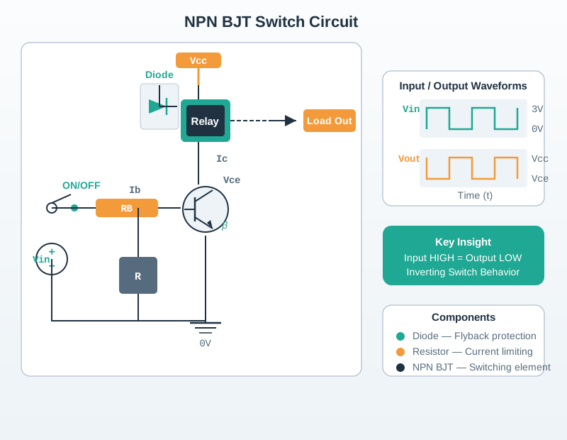
In Figure 15.1, begin at the 3.3 V GPIO and follow its small base current through the 330 Ω resistor into the NPN transistor. The 5 V supply, not the GPIO, drives 80 mA through the relay coil and switched return. With a forced gain of 10, 80 mA / 10 = 8 mA of base current, which makes 330 Ω a suitable nearby standard resistor for the shown drive. At turn-off, shift to the diode loop across the coil. It gives the stored magnetic energy a local path instead of letting transistor voltage rise sharply.
With a low-side NPN transistor driving that 5 V, 80 mA coil, choose the transistor for more than 80 mA collector current, then drive it into saturation with a conservative forced gain. If you assume forced gain of 10, base current is about 80 mA / 10 = 8 mA. From a 3.3 V GPIO and a 0.7 V base-emitter drop, a base resistor near (3.3 - 0.7) / 0.008 = 325 ohm is implied; a nearby standard value such as 330 ohm is the right order. A logic MOSFET often wastes less GPIO current, but the same flyback diode is still needed because the coil energy has not disappeared.
Contact ratings are a separate problem from coil ratings. The same 5 V, 80 mA coil might switch a 12 V pump at 2 A, a 24 V valve at 0.4 A, or a mains lamp. If a contact says 10 A resistive, that does not automatically mean 10 A motor or transformer load. A motor that runs at 4 A may draw 5 x 4 = 20 A for a short startup interval, and an inductive load can arc as the contacts open. For design margin, a 4 A inductive load is often treated as needing a 10 A to 15 A contact class, plus a snubber, MOV, or other suppression matched to the load.
Solenoids add a pulse-energy budget. A 12 V latch solenoid drawing 1.2 A for 200 ms uses 12 x 1.2 x 0.2 = 2.88 J per actuation. Ten actuations per day consume only 28.8 J/day in the coil, but the 1.2 A pulse can still sag a small battery or reset a controller if wiring resistance and bulk capacitance are ignored. Relays and solenoids look binary in software, but their current, stored energy, contact stress, and fail-safe state are analog design constraints.
Switching technology changes the loss and failure tradeoff. A mechanical relay with 50 milliohm contact resistance at 5 A dissipates I^2R = 25 x 0.05 = 1.25 W at the contacts. A triac-output AC SSR may drop about 1.6 V, so at the same 5 A it dissipates 1.6 x 5 = 8 W and needs a thermal path. The SSR wins when silence, high cycle life, or zero-cross AC switching matters; the mechanical relay wins when true open-circuit isolation, low leakage, and low on-state loss matter. For DC loads that need fast PWM, a MOSFET switch is usually the better actuator driver than either relay type.
Finally separate coil suppression from contact suppression. A diode across a DC relay coil protects the transistor. An RC snubber or MOV across relay contacts protects the contacts when the load itself is inductive. Putting the diode in the contact path or across the wrong terminals can leave the real fault untouched, so trace the current path during both on-time and turn-off before approving the wiring.
15.6.1 Under the Hood: Inductive Kickback
An inductor opposes changes in its current, and its voltage is V = L x (di/dt). When a transistor switches a relay or solenoid coil off, the current tries to stop almost instantly, so di/dt is enormous and the coil generates a large reverse voltage spike. That spike punches through the switching transistor or microcontroller pin unless a clamp gives the current a safer path.
The stored energy is easy to estimate. A relay coil with L = 100 mH and I = 80 mA stores 0.5 x 0.1 x 0.08^2 = 0.00032 J, or 0.32 mJ. That energy is small, but if current is forced from 80 mA to zero in 1 microsecond, the ideal inductor voltage is 0.1 x 0.08 / 1e-6 = 8000 V. Real parasitic capacitance, arcing, and transistor avalanche limit the voltage before that ideal value, but without a clamp the circuit chooses a destructive voltage high enough to keep current flowing.
A diode clamp changes the time scale. With the same 5 V, 80 mA coil, coil resistance is about 62.5 ohm. When a diode conducts, current circulates through the coil and diode while the magnetic field collapses. The clamp voltage is only about 0.7 V plus winding resistance effects, so the driver sees a safe voltage, but the relay releases more slowly because current decays gently. If a solenoid lock must release quickly, designers sometimes clamp at a higher voltage using a diode plus Zener or a TVS diode; the higher clamp dissipates the same stored energy faster while staying below the transistor’s safe rating.
15.7 Summary
This section: Summary — Relays and solenoids are simple to command but unforgiving to drive incorrectly.
Relays and solenoids are simple to command but unforgiving to drive incorrectly. Both require a driver stage between GPIO and coil, both need flyback protection, and relay contact choice must be checked against the load type, voltage, current, and desired fail-safe state.
Relays provide essential electrical isolation between low-power microcontrollers and high-power loads, while solenoids enable fast linear actuation for locks and valves. Both are inductive loads that absolutely require flyback diode protection. For high-voltage AC switching, always use properly rated components, enclosed wiring, fuses, and consult a licensed electrician for permanent installations.
15.8 Knowledge Check
This section: Knowledge Check
15.9 Concept Relationships
This section: Concept Relationships
| Concept | Relates To | Connection Type |
|---|---|---|
| Flyback Protection | Actuator Safety | Diodes clamp inductive voltage spikes |
| Electrical Isolation | High-Voltage Safety | Relays separate low-voltage control from AC mains |
| Inductive Loads | DC Motors | Motors require same flyback protection as relays |
| SSR vs Mechanical | Actuator Classifications | Decision tree for switching technology |
Common Pitfalls
This section: Common Pitfalls
Relay coils typically require 50-100 mA to energize, far exceeding the 20-40 mA GPIO limit. Connecting a relay coil directly to GPIO causes excessive current draw that permanently degrades or destroys the GPIO output driver. Always use a NPN transistor (2N2222, BC337) or MOSFET with a base/gate resistor to drive relay coils from a separate power source.
When the transistor cuts coil current, the relay/solenoid’s inductance generates a voltage spike of 10-100 V above the supply rail. Without a flyback diode (placed reverse-biased across the coil, cathode to positive supply), this spike destroys the driver transistor. This is the most common relay wiring mistake and a non-negotiable requirement.
AC solid state relays switch using triac or SCR devices that only work correctly with AC loads. Connecting an AC SSR to a DC load causes it to never turn off (or never turn on) due to the zero-crossing detection circuitry. Use a DC-rated SSR (using MOSFET output) for DC loads such as 12 V motors, heaters, and LED strips.
NC relay contacts are connected (load powered) when the relay is de-energized, making them appear safe for fail-safe applications. However, if the coil burns out or the driver fails, the relay remains de-energized and NC contacts remain closed — potentially leaving a load permanently powered. Design fail-safe systems carefully, considering which failure mode is safer for your specific application.
15.11 What’s Next
This section: What’s Next
| If you want to… | Read this |
|---|---|
| Understand PWM control fundamentals for motor and dimmer control | PWM Control |
| Learn about DC motor control for higher-power motor applications | DC Motors |
| Explore actuator safety circuits and protection design | Actuator Safety |
| Practice relay and solenoid control in hands-on labs | Actuator Labs |
15.12 Continue Your Route
This section: Continue Your Route — This is the last part of this chapter.
This is the last part of this chapter. Return to Relays and Solenoids: Drivers and Protection or continue from the actuators module index.
Find help
3 reviewed answers.
Where should I start in a module?
Open the module page from the sidebar to see its chapters in order. Use the module map to return to a topic you need.
Modules and pathsReviewed
What can I try when a project does not work?
Check the symptom, then work through the diagnostic steps. Keep the error message and the smallest example that reproduces it.
When you are stuckReviewed
How do interactive examples work?
Use the interactive guide to check how examples and simulations work before changing your project.
Interactive examples guideReviewed