3 RF Localisation with RSSI, Time, Angle, UWB, and Sensor Fusion
3.1 Start With the Story
Radio Remi must find a medicine cart on a busy hospital floor. The nearest access point is not always the nearest cart position because walls bend and weaken radio paths. Remi gathers labelled signal fingerprints, checks where clocks and antenna arrays are available, and keeps a motion estimate between fixes. The result must show ordinary and bad errors, not one perfect dot.
3.2 Overview
RF localisation turns signal strength, travel time, arrival-time difference, or arrival angle into geometric evidence. RSSI can use common radios but is strongly shaped by the site. Fingerprinting learns that site instead of assuming a perfect path-loss model. ToF and UWB use timing, TDoA needs synchronized anchors, and AoA needs array calibration. Sensor fusion can connect sparse radio fixes, but it also carries motion-sensor drift.
3.3 Learning Objectives
By the end of this chapter, you will be able to:
- Compare RSSI, fingerprinting, ToF, TDoA, AoA, and UWB by their measurement assumptions.
- Fuse a fixed RSSI training map with motion evidence and score held-out positions.
- Use median and p90 error to make a bounded deployment choice.
3.4 Match the observable to the geometry
RSSI estimates loss, so one range-like value forms a broad ring rather than a point. A fingerprint compares a live vector with labelled survey vectors. Time of flight estimates distance from propagation time. TDoA forms a hyperbola from arrival-time differences at synchronized anchors. AoA supplies a direction from array phase. UWB offers fine timing, yet non-line-of-sight paths and poor anchor geometry still bias the result.
3.5 Read the localisation evidence map
Begin at the left card, where RSSI, timestamps, or array phase enter with calibration and clock limits. The centre card applies a path-loss fit, fingerprint match, geometric solver, or fusion update. The right card reports a position with confidence and error percentiles. The red boundary under the cards reminds us that a map and a notebook do not prove performance in another building.
Figure Figure 3.1 keeps the stages in reading order. Begin at the left card, where RSSI, timestamps, or array phase enter with calibration and clock limits.
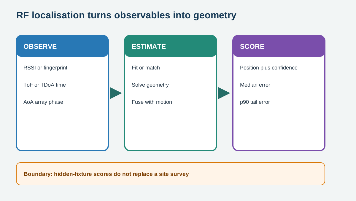
In Figure 3.1, read left to right, then use the final boundary note to limit the conclusion. The arrows show processing order, not proof that the final output is correct in every setting.
3.6 Fuse without hiding drift
A motion estimate can predict where a handset moved between radio observations. The next RF fix then corrects part of the drift. Fusion works only when coordinate frames, timestamps, units, and uncertainty agree. A smooth track may still be wrong if both inputs share a bias. Keep the RSSI-only result beside the fused result so an improvement remains visible and reversible.
The prediction covariance should grow while radio updates are missing because the unknown position is becoming less certain. A measurement update should shrink uncertainty only as far as its calibrated error model allows. Logging each innovation exposes radio fixes that disagree sharply with the motion path. A rejection gate can contain one unlikely fix, but repeated rejections signal a model or reference-frame problem.
3.8 Plan the anchor geometry
Anchor placement determines which directions and distances the measurements can constrain. Collinear anchors create weak geometry because several candidate positions produce similar ranges. Wider viewing angles improve the solver’s ability to separate movement along different axes. A survey record should preserve anchor coordinates, mounting height, clock role, antenna orientation, and any blocked region.
Coverage also needs redundant observations where the system makes an important hand-off or alarm. A floor plan can predict geometry, but only measured paths expose attenuation and non-line-of-sight bias. The acceptance set should include edge points and transitions rather than only positions near the centre. Maintenance checks must detect a moved anchor before its bias silently shifts every reported position.
3.9 Decision and Trade-offs
Use RSSI fingerprinting when low-cost existing infrastructure and site surveys are acceptable. Use UWB ToF for stronger ranging evidence when tags, anchors, airtime, and calibration fit. Use TDoA for many transmit-only tags only when anchor time is controlled. Use AoA when direction adds value and array calibration is supportable. Add fusion when its timing and drift can be tested separately.
3.10 Practice the Method
The linked lab uses a prepared online tool and retains its result evidence. Complete the steps, compare the result with the chapter boundary, and name one condition that the exercise did not test.
3.11 Check Your Reasoning
3.12 Summary
The useful result is a location estimate whose frame, calibration, and tail error remain attached. Report where the anchors were, how the reference data were collected, and how the held-out route differed. Those details make the estimate reproducible and reveal whether a method works across the whole test area or only near favourable anchors.
- Each localisation method turns a different observable into geometry under different assumptions.
- Fusion can reduce gaps, but it cannot erase shared bias or missing calibration.
- Median and p90 error on a held-out path are stronger evidence than one best-case fix.