5 Lidar and Optical Ranging for IoT
5.1 Start With the Story
Radio Remi is helping a warehouse door slow down before a trolley reaches it. The team can point a small optical sensor at one zone, scan a laser across the aisle, or use radar or sound. Clear plastic, fog, bright light, soft surfaces, and moving people change those choices. Remi tests what each sensor can actually observe before choosing a stop distance.
5.2 Overview
Lidar measures distance with light. Direct time-of-flight systems estimate the round-trip travel time of a pulse or modulated signal. Structured light projects a known pattern and infers depth from its displacement. A 2D scanner measures a plane, while a 3D unit samples elevation too. Low-cost VL53-class modules provide a small optical ranging zone suited to nearby targets, not a complete 3D scene.
5.3 Learning Objectives
By the end of this chapter, you will be able to:
- Explain direct optical time of flight and structured-light depth.
- Compare 2D and 3D lidar with low-cost single-zone ToF modules.
- Choose among lidar, radar, and ultrasonic sensing using environment, privacy, cost, and power evidence.
5.4 Light travel time and return strength
A direct time-of-flight range follows R = ct/2, where c is the speed of light and t is round-trip delay. Real sensors estimate that delay from photons, modulation phase, or correlation rather than a perfect stopwatch. Reflectivity, target angle, ambient light, window contamination, cover glass, and crosstalk affect return strength and confidence. A range without a status or quality value is incomplete evidence.
An integration must keep the sensor’s field of view separate from the object’s physical width. A wide field can mix foreground and background returns, while a narrow field can miss a moving target. Repeated samples reveal jitter and dropouts that one favourable reading hides. A valid-range rule should preserve invalid status rather than clipping every observation into the accepted interval.
5.5 From one zone to a point cloud
A single-zone module reports one range over its field of view. A multi-zone sensor reports a small depth grid. A 2D lidar rotates or scans a beam across azimuth, and a 3D lidar also samples elevation. Motion during a scan can bend the apparent scene unless timestamps and pose are used. Structured light is strong at short range but can struggle in bright sun or on difficult surfaces.
5.6 Choose the modality
Start at the left of the comparison diagram with the environment: fog, glass, walls, surface angle, and required field of view. The middle cards show what light, radio, and sound interact with. The final card turns those conditions into a choice plus a fallback. No single modality wins on range, resolution, cost, power, privacy, and weather at once.
The comparison begins with the decision that the system must support, not with a preferred component. Required update rate, closest safe distance, mounting position, and target material constrain the available evidence. A fallback can slow a machine, ask for another reading, or transfer authority to a separate protective device. Field trials must preserve misses and invalid returns because deleting them would make the chosen modality look more reliable.
Figure Figure 5.1 keeps the stages in reading order. Start at the left of the comparison diagram with the environment: fog, glass, walls, surface angle, and required field of view.
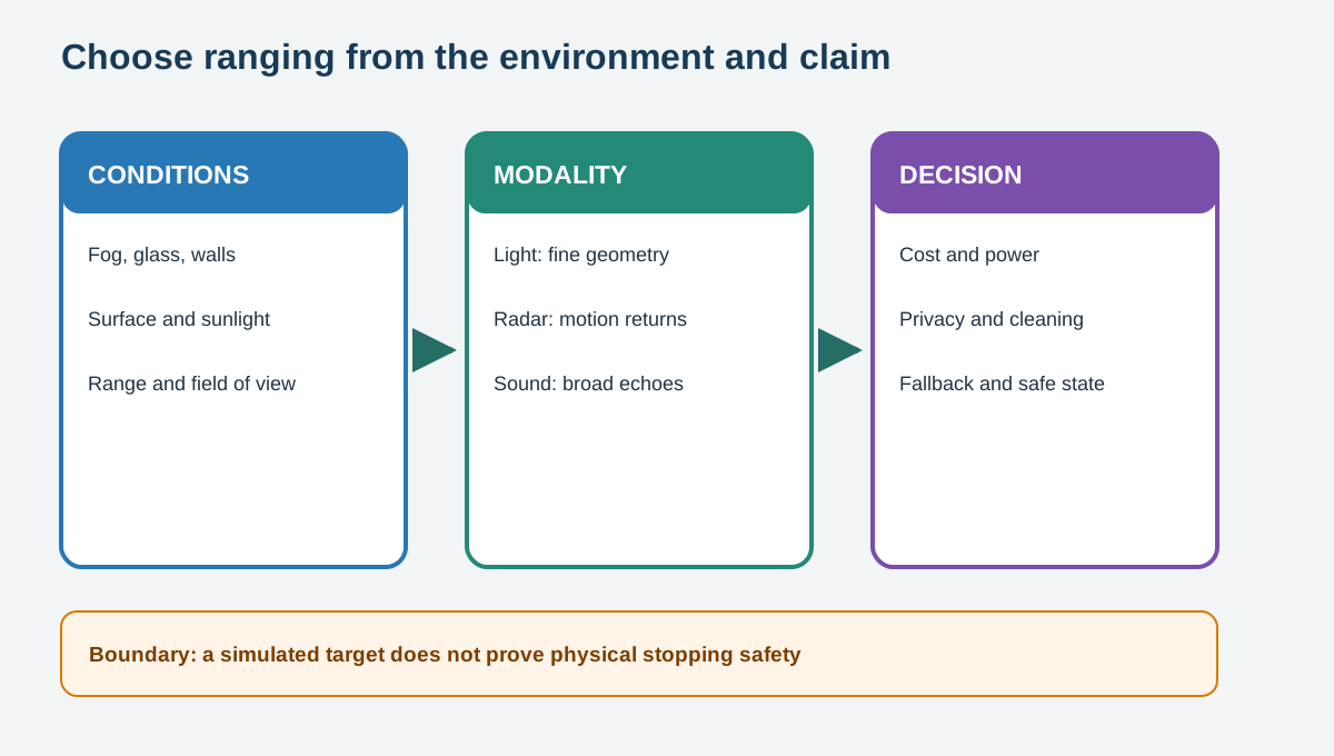
In Figure 5.1, read left to right, then use the final boundary note to limit the conclusion. The arrows show processing order, not proof that the final output is correct in every setting.
5.7 VL53-class integration boundaries
A VL53L0X-style module uses I2C for configuration and distance results. Firmware should check initialization, timeout, status, units, and plausible bounds before acting. The Wokwi lab changes an explicitly labelled range-input surrogate and prints millimetres beside one HC-SR04 comparison line. That verifies the comparison code, not a VL53L0X transaction, eye safety, cover-window design, sunlight tolerance, or physical stopping distance.
The current Wokwi catalogue does not provide a VL53L0X optical model, so the lab states this boundary in its diagram, code, and serial output. The adjustable control exercises unit conversion and comparison without claiming a photon-return simulation. Real hardware acceptance still needs known targets, difficult surfaces, ambient-light trials, and recorded status codes. A protective stop needs an independently justified safety function rather than the lab’s distance threshold.
5.8 Decision and Trade-offs
Choose a VL53-class module for a compact nearby zone when optical line of sight and target surfaces are controlled. Choose scanning lidar for detailed geometry when budget, power, cleaning, and privacy controls fit. Choose radar for motion and range through some obscurants, accepting sparse returns and RF complexity. Choose ultrasonic for low-cost short range where beam width, echoes, airflow, and soft surfaces are acceptable.
5.9 Practice the Method
The linked lab uses a prepared online tool and retains its result evidence. Complete the steps, compare the result with the chapter boundary, and name one condition that the exercise did not test.
5.10 Check Your Reasoning
5.11 Summary
The useful choice connects a spatial question to a modality, a fallback, and named environmental limits. Record the target material, range, lighting, weather, field of view, update rate, and safety role before comparing devices. Those conditions explain why a sound bench result may not transfer to glass, fog, sunlight, or a moving platform.
- Optical ranging estimates light travel or pattern displacement under return-quality limits.
- Single-zone ToF, 2D lidar, 3D lidar, radar, and ultrasound answer different spatial questions.
- A simulator checks code paths but cannot validate sunlight, fog, glass, stopping safety, or sensor calibration.