Prototype a VL53L0X range decision in Wokwi
Exercise a VL53L0X firmware decision path with an explicit Wokwi range-input surrogate and compare it with one HC-SR04 line without claiming physical-sensor evidence.

Radio Remi: compare the two readings, then state exactly what the simulator did not test.
Predict the reading, then compare it with the measurement.
Wokwi ESP32
Third party ToolExercise a VL53L0X firmware decision path with an explicit Wokwi range-input surrogate and compare it with one HC-SR04 line without claiming physical-sensor evidence.
Open the ESP32 editor, paste diagram.json, then paste sketch.ino.
Open Wokwi to paste in the files (new tab)Get the files
Use both prepared files. This is a paste-in setup; saving a project requires a Wokwi account.
sketch.ino
- Use the launch button above to open the ESP32 editor in Wokwi.
- Select the editor’s diagram.json tab and replace all its text with the supplied diagram.json.
- Select the sketch.ino tab, replace all its text with the supplied sketch.ino, then click Start Simulation.
Steps
Step 1
- Do
- In diagram.json, identify the labelled optical-range surrogate and the HC-SR04 trigger and echo wiring.
- You will see
- The ESP32 reads a controlled range input on GPIO 34 and a simulated ultrasonic pulse path on GPIO 18 and 19.
- Why it matters
- Wokwi currently lacks a VL53L0X part, so the surrogate tests only the range-decision path; a physical module would use I2C.
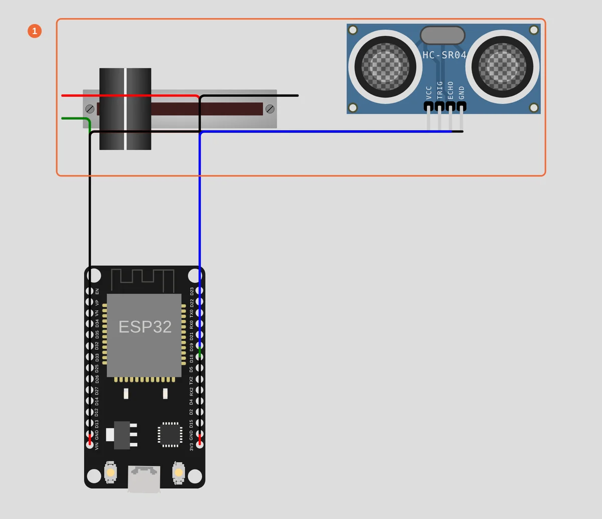
Step 1 · Wokwi ESP32; numbered callout added to a real capture. Enlarge screenshot (new tab) Step 2
- Do
- In sketch.ino, find the surrogate boundary, millimetre conversion, and ultrasonic comparison line.
- You will see
- The code labels simulated optical status and ultrasonic centimetres separately.
- Why it matters
- Firmware should keep source, status, units, and plausible bounds visible before acting.

Step 2 · Wokwi ESP32; numbered callout added to a real capture. Enlarge screenshot (new tab) Step 3
- Do
- Start the Wokwi simulation and open Serial Monitor.
- You will see
- Serial Monitor prints RANGING READY and names the surrogate before the first sample.
- Why it matters
- The lab changes a bounded range input and prints millimetres beside one HC-SR04 comparison line.
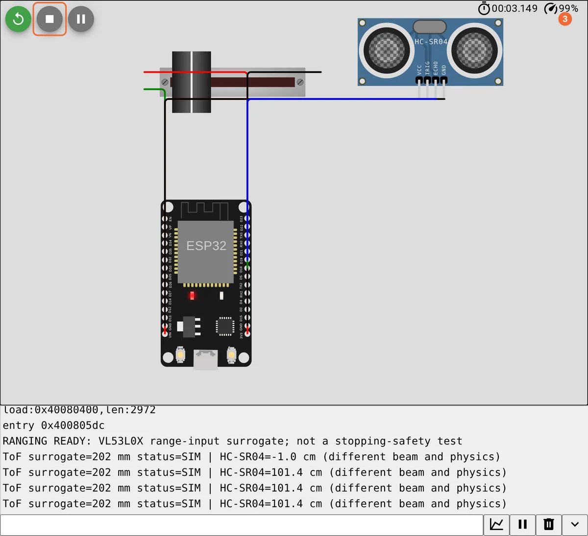
Step 3 · Wokwi ESP32; numbered callout added to a real capture. Enlarge screenshot (new tab) Step 4
- Do
- Leave the optical-range control near 200 mm and the ultrasonic target at 100 cm.
- You will see
- A line reports about 200 mm for the ToF surrogate and 100 cm for HC-SR04.
- Why it matters
- Holding one target fixed makes the units and paths visible before a change.
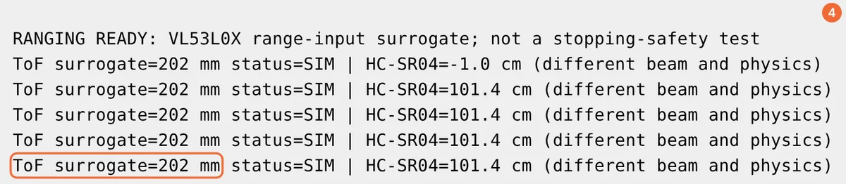
Step 4 · Wokwi ESP32; numbered callout added to a real capture. Enlarge screenshot (new tab) Step 5
- Do
- Turn the labelled VL53L0X range-input control to the prepared 500 mm fixture.
- You will see
- The next surrogate line changes to about 500 mm while HC-SR04 stays near 100 cm.
- Why it matters
- Changing one input at a time exposes which reading the control affects.
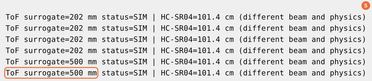
Step 5 · Wokwi ESP32; numbered callout added to a real capture. Enlarge screenshot (new tab) Step 6
- Do
- Restart and read the declared safety boundary.
- You will see
- Serial Monitor states that the run is not a stopping-safety test.
- Why it matters
- A simulator result cannot establish braking distance or physical sensor behaviour.

Step 6 · Wokwi ESP32; numbered callout added to a real capture. Enlarge screenshot (new tab)
Chapter checks
These questions refer to the chapter’s examples. Use the return links to review their answers.
Why should a ToF reading carry a status or confidence value?
Return to the chapter’s knowledge checkWhich choice best fits one controlled, nearby optical zone?
Return to the chapter’s knowledge check