9 State Machines in IoT
9.1 Start With the Device Mode
A state machine starts when “the device is running” is no longer precise enough. A gateway might be idle, joining, connected, retrying, degraded, or locked out, and each mode allows different events.
For IoT, naming those modes turns vague behavior into a contract that developers, operators, and testers can inspect. Start with one device mode, one event, and one allowed transition; the rest of the state model grows from those visible promises.
9.2 Learning Objectives
By the end of this section, you will be able to:
- Explain why IoT systems use state machines to make device behavior checkable.
- Route a learning path through fundamentals, implementation practice, and reusable design patterns.
- Choose whether a behavior belongs in a device, gateway, service, or coordinated multi-machine design.
- Compare Moore, Mealy, hierarchical, and parallel state-machine styles at a practical level.
- Check IoT state-machine designs for fault paths, timeout behavior, guard/action separation, persistence, and transition coverage.
9.3 Minimum Viable Understanding
A state machine is useful when a system has named modes and clear events that move it between modes. In IoT, those events often come from timers, sensors, radio links, buttons, gateway messages, reset causes, or service acknowledgements.
Use this route:
- Name the behavior boundary: decide whether the state machine owns device firmware, gateway coordination, service workflow, or a small subsystem.
- Name states and events: keep states stable and events concrete.
- Build the transition table: define source state, event, guard, action, next state, and expected proof.
- Choose the style: use Moore, Mealy, hierarchy, or parallel machines based on inspectability and coupling.
- Verify the paths: test normal, invalid, timeout, retry, fault, reset, and coordination paths.
9.4 Section Map
This section has three companion chapters. Each one has a different role.
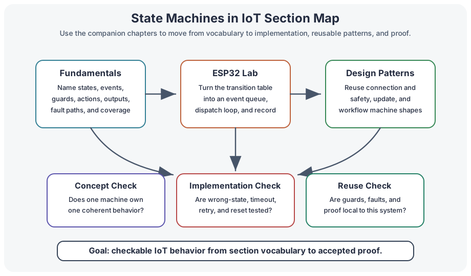
State Machine Fundamentals
Use this chapter first when you need the vocabulary: state, event, transition, guard, action, output, fault path, and transition coverage.
Lab: ESP32 State Machines
Use this lab when you want to turn a transition table into a compact event-driven firmware loop and test record.
State Machine Design Patterns
Use this chapter when you need reusable patterns for connection management, duty cycling, safety, and coordination.
9.5 Where State Machines Fit in IoT
State machines can appear at several layers. The key is to keep each machine responsible for one coherent behavior.
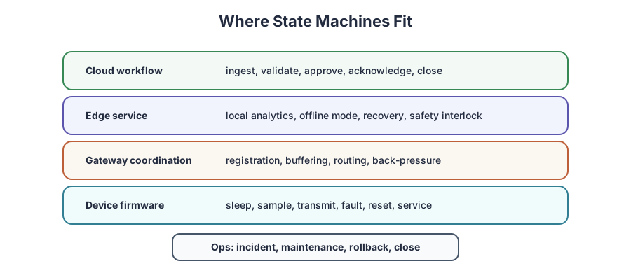
Common placements:
- Device firmware: sleep, sample, transmit, fault, service, and reset behavior.
- Gateway coordination: device registration, link health, local buffering, command routing, and back-pressure.
- Edge service: local analytics, safety interlocks, offline mode, and recovery after network loss.
- Cloud workflow: ingest status, approval workflow, alert lifecycle, and command acknowledgement.
- Operations process: incident states, maintenance handoff, rollback decision, and closure check.
Avoid one giant state machine that owns everything. Split behavior where ownership, timing, or failure domains differ.
9.6 State-Machine Styles
The style is a design choice. Pick the style that makes behavior easiest to prove.
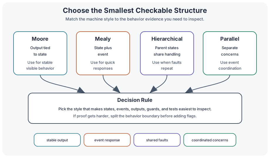
Moore Style
Outputs are tied to state. This is useful when visible behavior should be stable and easy to inspect.
Mealy Style
Outputs may depend on state and event. This can be responsive, but event handling needs careful tests.
Hierarchical Style
Parent states share behavior across child states. This reduces duplicated transitions and common fault handling.
Parallel Machines
Independent concerns run as separate machines and coordinate through events instead of one flat combined state.
9.7 Pattern Families
Many IoT systems reuse a small set of state-machine patterns.
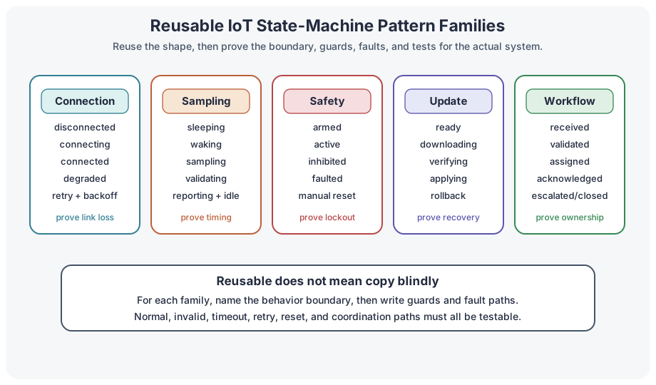
Useful families:
- Connection pattern: disconnected, connecting, connected, degraded, retry, and backoff behavior.
- Sampling pattern: sleeping, waking, sampling, validating, reporting, and returning to idle.
- Safety pattern: armed, active, inhibited, faulted, manual reset, and service override behavior.
- Update pattern: ready, downloading, verifying, applying, rollback, and confirmed behavior.
- Workflow pattern: received, validated, assigned, acknowledged, escalated, resolved, and closed behavior.
Patterns are starting points, not templates to paste blindly. Every pattern still needs guards, fault handling, and tests matched to the actual system boundary.
9.8 Coordination Without State Explosion
State explosion happens when independent concerns are forced into one flat model. A gateway that tracks device link state, local buffer state, and command state should usually model those as separate machines that exchange events.
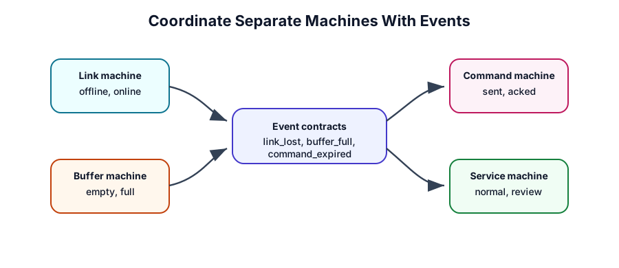
Use separate machines when:
- The concerns can change independently.
- Each concern has its own owner or test plan.
- Combining them creates many artificial state names.
- Coordination can be expressed as events such as
link_lost,buffer_full,command_acked, orbattery_low.
Use one combined machine when:
- The states are inseparable in real behavior.
- One transition must update all outputs atomically.
- Separate machines would hide a safety-critical dependency.
9.9 Build Gateway State Machines
A building gateway receives sensor reports, buffers data during network outages, and forwards commands to local controllers. A flat design tries to combine link status, buffer status, command lifecycle, and maintenance mode into one diagram. The design check should split the concerns.
Recommended split
-
Link machine:
offline,joining,online,degraded,recovering. -
Buffer machine:
empty,collecting,near_limit,full,draining. -
Command machine:
idle,received,validated,sent,acknowledged,expired,rejected. -
Service machine:
normal,maintenance,locked_out,manual_check.
Coordination events
Event: link_lost
From: Link machine
To: Buffer machine
Expected behavior: buffer enters collecting or near_limit based on capacity

Event: buffer_full
From: Buffer machine
To: Command machine and Service machine
Expected behavior: new noncritical commands are rejected and service check is opened

Event: command_expired
From: Command machine
To: Service machine
Expected behavior: unresolved command is visible for operator check
This structure keeps each machine small while making coordination visible.
9.10 State-Machine Proof Checklist
Before accepting an IoT state-machine design, check the proof.
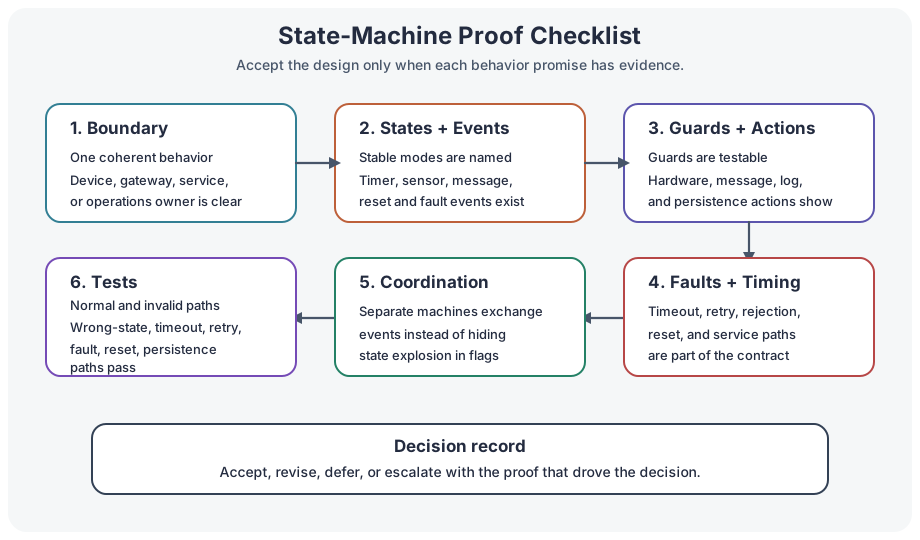
Ask:
- Boundary: does the machine own one coherent behavior?
- States: does each state represent a stable mode rather than a temporary flag?
- Events: are timer, sensor, message, reset, and fault events named clearly?
- Guards: are guards side-effect free and testable?
- Actions: are hardware, message, logging, and persistence actions explicit?
- Faults: are timeout, retry, rejection, reset, and service paths covered?
- Coordination: are interactions between machines represented as events?
- Tests: does the test matrix include invalid and wrong-state events, not only the happy path?
9.11 Knowledge Check
9.12 Common Pitfalls
- One machine owns too much: unrelated device, gateway, and service behavior becomes a single untestable diagram.
- Flags hide extra states: boolean flags create combinations that are not visible in the transition table.
- Faults are afterthoughts: timeout, retry, reset, and manual-service paths are added late or not tested.
- Guards do work: guard checks send messages, write storage, or change outputs instead of only deciding.
- Persistence is automatic: unsafe states are restored after reset without a recovery decision.
- Only happy paths are tested: invalid events, wrong-state messages, and coordination failures remain unverified.
9.13 Overview: A State Machine Owns Behavior
A state machine is not just a diagram of possible modes. It is an ownership boundary: this machine accepts these events, keeps this context, performs these actions, and refuses or escalates everything outside that contract.
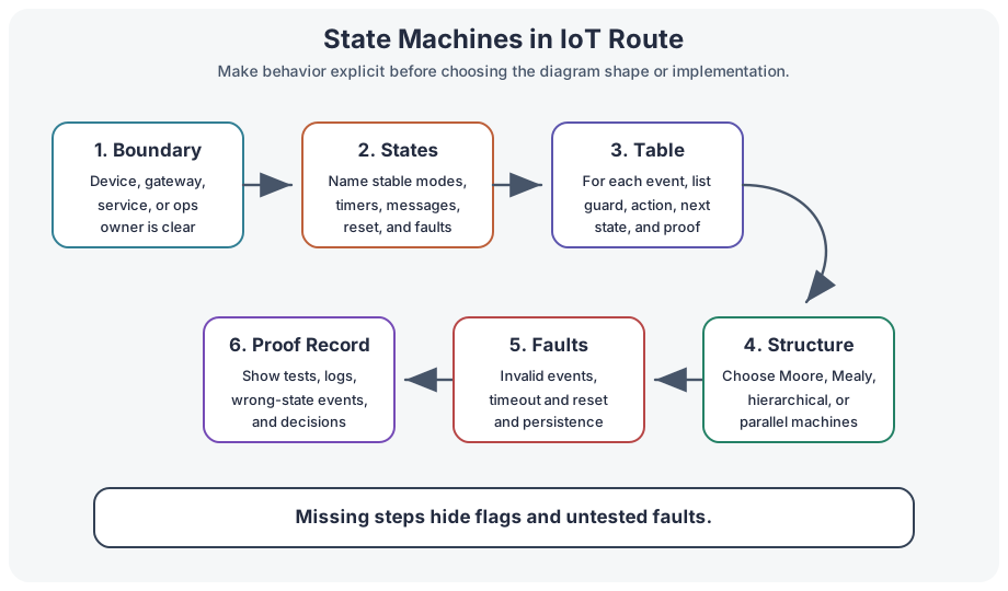
Small-screen read: The route is behavior boundary, states and events, transition table, structure, and proof. If any step is missing, hidden flags and untested fault paths usually appear.
That ownership is valuable in IoT because behavior crosses unreliable boundaries. A sensor can report late, a gateway can lose backhaul, a command can expire, and a device can reboot in the middle of work. The state machine makes those cases visible instead of leaving them as scattered flags.
9.14 Practitioner: Write The Event Contract
Before implementing the transition table, write the event contract. It prevents each layer from inventing its own meaning for a message, timeout, retry, reset, or operator action.
Event Source
Name whether the event came from a sensor, timer, radio stack, gateway, cloud service, operator, or stored recovery record.
Allowed State
Name which source states may accept the event, which states must reject it, and what evidence is logged for wrong-state events.
Action And Proof
Name the action, emitted event, persisted field, acknowledgement, timeout, and test that proves the transition happened as intended.
For a gateway command, the event contract might say: command_received is valid only in online or degraded, requires a freshness check, emits command_sent or command_rejected, and must expire locally if no acknowledgement arrives inside the command lifetime.
9.15 Under the Hood: Reset Is A Transition
Reset and persistence are where many IoT state machines become unsafe. If firmware simply restores the previous state after power loss, it may resume a command, service mode, or safety state whose assumptions are no longer true.
Treat reset as an explicit transition. Decide which states can be restored, which must enter recovery, which outputs must be inhibited, which pending events must expire, and which proof must be rebuilt before normal operation resumes.
9.16 Summary
State machines help IoT teams make behavior explicit across devices, gateways, services, and operations workflows. Use fundamentals to name the model, use the lab to practice implementation and verification, and use design patterns to reuse proven structures without hiding system-specific proof. The acceptance standard is simple: every important state, event, guard, action, fault path, coordination event, and test expectation should be visible.
9.17 Key Takeaway
State machines make IoT firmware and workflows easier to reason about when every transition has a trigger, guard, action, and test.
9.18 See Also
- State Machine Fundamentals for IoT: core vocabulary and transition-table checks.
- Lab: ESP32 State Machines: implementation and verification practice.
- State Machine Design Patterns: reusable IoT state-machine patterns.
- Processes and Systems Fundamentals: system behavior, feedback, and mode changes.
- Production Architecture Management: operational checks and proof handoff.
9.19 What’s Next
Start with State Machine Fundamentals for IoT if you need the core concepts, use Lab: ESP32 State Machines for implementation practice, or continue to State Machine Design Patterns when you are ready to choose reusable patterns.