12 Lab: ESP32 State Machines
12.1 Start With the First Event Trace
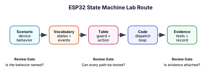
The lab is not mainly about drawing boxes. It is about proving that an ESP32 reacts to events in the order the design promised: button press, timer tick, sensor threshold, network response, or fault condition.
Start by writing one trace from initial state to expected output. Then build the state machine so the serial log, LED, or network message can prove each transition happened for the right reason.
12.2 Learning Objectives
By the end of this lab, you will be able to:
- Convert button, timer, sensor, and fault inputs into explicit state-machine events.
- Build a transition table with source state, event, guard, action, next state, and expected output.
- Implement a small event-driven FSM loop without hiding behavior in scattered flags.
- Add guards, timeouts, retry limits, reset behavior, and persistence decisions deliberately.
- Produce a test matrix and proof record that shows the state machine handles normal, invalid, timing, and recovery paths.
12.3 Lab Outcome
You will produce three artifacts:
- Transition table: the checkable behavior contract for the device.
- Implementation skeleton: a compact firmware loop that dispatches events to the transition rules.
- Verification record: proof that each state/event path was tested or deliberately rejected.
12.4 Prerequisites
Use these chapters as needed:
- State Machine Fundamentals for IoT: states, events, transitions, guards, actions, outputs, and test coverage.
- State Machines in IoT: applying state-machine thinking across device, gateway, and service workflows.
- Microcontroller Programming Essentials: GPIO input, output, and firmware loop structure.
12.5 Scenario
Build a small environmental-node controller with four visible states:
IDLE
The node waits for a sample request or scheduled timer event.
SAMPLE
The node starts the sensor, waits for completion, and validates the result.
TRANSMIT
The node queues the latest sample and waits for an acknowledgement.
FAULT
The node records the failure reason, sets safe outputs, and waits for reset or service action.
The same structure can run on a physical ESP32 board or in a browser simulator. If you use a simulator, treat it as a way to observe events and outputs; do not make the lab depend on a one-off external project file.
12.6 Hardware Boundary
Keep the hardware boundary simple so the state machine remains the focus.
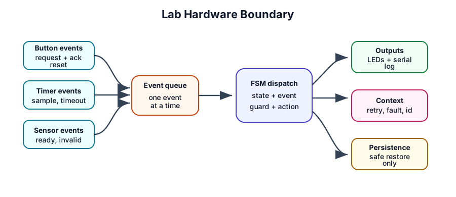
Suggested inputs and outputs:
| Signal | Role in the lab | Notes |
|---|---|---|
| Button A | EV_SAMPLE_REQUEST |
Manual request to start a sample cycle. |
| Button B | EV_ACK_RECEIVED |
Simulates a gateway acknowledgement. |
| Button C | EV_SAMPLE_INVALID |
Simulates a failed sensor validation. |
| Reset button | EV_RESET |
Returns from FAULT to a known state when allowed. |
| Timer | EV_TIMEOUT |
Drives sampling cadence and acknowledgement timeout. |
| LEDs or serial log | State/output proof | Show current state and transition record. |
12.7 Step 1: Name States, Events, and Context
Before coding, write the vocabulary of the machine.
-
States:
IDLE,SAMPLE,TRANSMIT, andFAULT. - Events: sample request, sample ready, sample invalid, acknowledgement received, timeout, retry limit reached, reset requested.
- Context: current state, retry count, latest sample identifier, timeout deadline, last fault reason, and whether recovery is allowed.
- Outputs: LED state, serial transition record, queued message, safe output, and optional persisted state.
Keep the context small. If the context grows without a clear purpose, the design is probably hiding extra states.
12.8 Step 2: Build the Transition Table
Use a table first. Diagrams are helpful, but the table is easier to test.
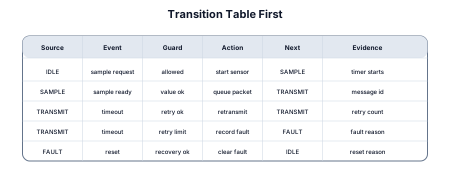
Minimum transition table:
| Source | Event | Guard | Action | Next | Expected proof |
|---|---|---|---|---|---|
IDLE |
sample request | allowed | start sensor; start timeout | SAMPLE |
sample timer starts |
SAMPLE |
sample ready | value valid | queue sample; start ack timer | TRANSMIT |
message id recorded |
SAMPLE |
sample invalid | confirmed | record fault reason | FAULT |
invalid-sample fault visible |
SAMPLE |
timeout | confirmed | stop sensor; record timeout | FAULT |
sample timeout visible |
TRANSMIT |
acknowledgement | pending message exists | clear retry count | IDLE |
ack id recorded |
TRANSMIT |
timeout | retry allowed | increment retry; retransmit | TRANSMIT |
retry count increments |
TRANSMIT |
timeout | retry limit reached | stop radio; record fault | FAULT |
communication fault visible |
FAULT |
reset requested | recovery allowed | clear fault context | IDLE |
reset reason recorded |
Add rows for invalid or wrong-state events. For example, an acknowledgement in IDLE should be ignored, rejected, or logged as unexpected; it should not silently change state.
12.9 Step 3: Use an Event Queue
Buttons, timers, sensor callbacks, and communication callbacks should publish events. The state machine loop should consume events one at a time.
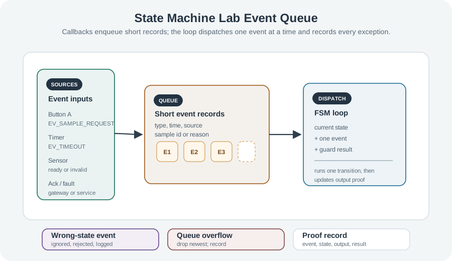
Implementation rules:
- Interrupts or callbacks should enqueue short event records, not run the full transition logic.
- The main loop should dispatch one event at a time to the current state.
- Queue overflow must have explicit behavior, such as dropping the newest event and recording the overflow.
- Events that arrive in the wrong state should be handled deliberately.
12.10 Step 4: Separate Guards and Actions
Guards decide. Actions do work.
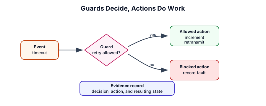
Use this discipline:
- Guard: checks retry count, sample validity, timeout status, or recovery permission.
- Transition action: increments retry count, queues a packet, records a fault, starts a timer, or clears context.
- Entry action: sets the LED or output mode for the new state.
- Exit action: stops work owned by the previous state.
- Blocked transition: records whether the event was ignored, rejected, or deferred.
12.11 Step 5: Implement a Small FSM Skeleton
The skeleton below is intentionally compact. It shows the shape of the implementation without hiding the design in a long code listing.
enum class State { Idle, Sample, Transmit, Fault };
enum class Event {
  SampleRequest, SampleReady, SampleInvalid,
  AckReceived, Timeout, ResetRequested
};

struct Context {
  State state = State::Idle;
  int retry_count = 0;
  int retry_limit = 2;
  bool recovery_allowed = true;
};

bool retry_allowed(const Context& ctx) {
  return ctx.retry_count < ctx.retry_limit;
}

void enter(State next, Context& ctx) {
  ctx.state = next;
  // Set LEDs, start state-owned timers, and log entry.
}

void dispatch(Event event, Context& ctx) {
  switch (ctx.state) {
    case State::Idle:
      if (event == Event::SampleRequest) {
        start_sensor();
        enter(State::Sample, ctx);
      }
      break;

    case State::Sample:
      if (event == Event::SampleReady) {
        queue_sample();
        start_ack_timer();
        enter(State::Transmit, ctx);
      } else if (event == Event::SampleInvalid ||
                 event == Event::Timeout) {
        record_fault("sample");
        enter(State::Fault, ctx);
      }
      break;

    case State::Transmit:
      if (event == Event::AckReceived) {
        ctx.retry_count = 0;
        enter(State::Idle, ctx);
      } else if (event == Event::Timeout && retry_allowed(ctx)) {
        ctx.retry_count++;
        retransmit();
      } else if (event == Event::Timeout) {
        record_fault("ack timeout");
        enter(State::Fault, ctx);
      }
      break;

    case State::Fault:
      if (event == Event::ResetRequested && ctx.recovery_allowed) {
        clear_fault();
        enter(State::Idle, ctx);
      }
      break;
  }
}
In your real code, add explicit handling for ignored or rejected events so tests can verify that the behavior was deliberate.
12.12 Add Persistence and Reset Behavior
Persistence is useful only when restoring a state is safe and meaningful. Some states should be restored as-is; others should be converted to a checked state such as FAULT or a known safe state such as IDLE.
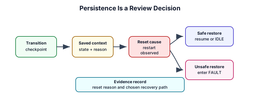
Check questions:
- Which context fields must survive reset?
- Which states are safe to restore directly?
- Which states should resume as
FAULTorIDLEinstead? - What proof shows why the device restarted?
- How often should state be written so persistence does not become a hidden side effect?
Avoid saving state on every loop iteration. Save only at deliberate transition points or check points.
12.13 Add Timeouts and Fault Recovery
Timeouts are events, not hidden waits.
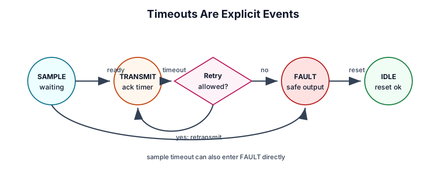
Run it: Operate a concrete ESP32 state machine below to see timeouts and faults as real transitions rather than hidden waits. Start from Clean lab, then inject Weak signal, Wrong password, and AP outage and watch the connection state machine move into retry, backoff, and fault states; open the Timeline and Handler views to see which event fired each transition, and the Power view to see what a Sleepy node costs. Map each fault path you observe onto the required timeout paths in this step’s list.
Required paths:
- Sample timeout: sensor did not produce a usable value before the deadline.
- Acknowledgement timeout with retry allowed: retransmit without taking a new sample.
-
Acknowledgement timeout with retry exhausted: stop communication work and enter
FAULT. - Reset while faulted: return only when the recovery guard permits it.
- Unexpected event: log, ignore, reject, or defer without changing state accidentally.
12.14 Step 8: Test the Transition Matrix
Testing proves the state machine is more than a diagram.
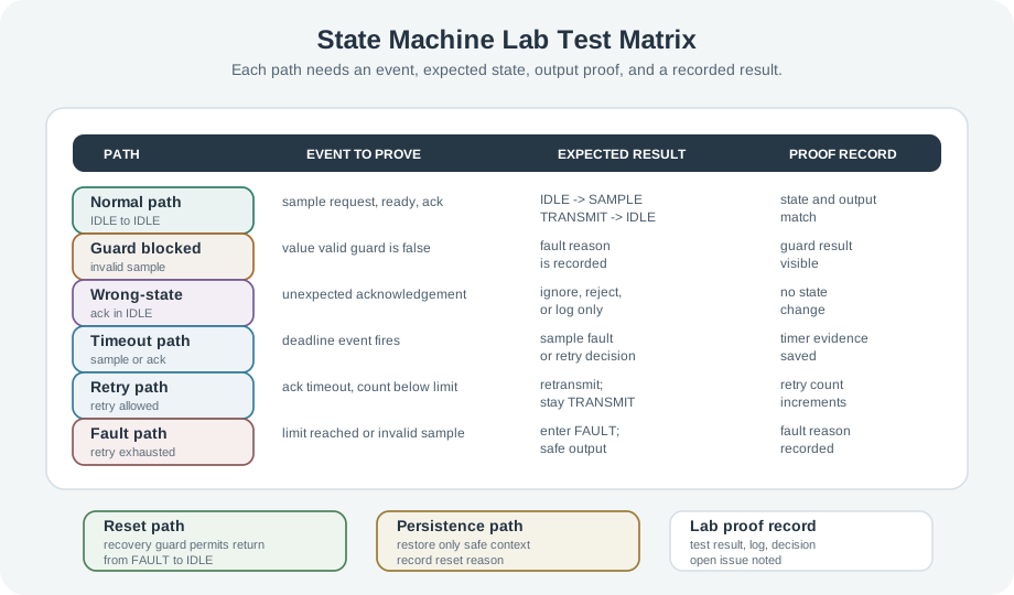
Run it: Rather than only reading the test matrix, run each case through the state-machine simulator below. Select a scenario, then Run and Step to drive the machine through normal, guard-blocked, wrong-state, timeout, retry, and fault paths, watching which transition fires and which is rejected. Use it to confirm each row of your test matrix produces the state and output the transition table promised before you write the proof record.
Test cases:
-
Normal path:
IDLE -> SAMPLE -> TRANSMIT -> IDLEwith expected output proof. -
Invalid sample:
SAMPLE -> FAULTwith the fault reason recorded. - Retry path: acknowledgement timeout increments retry count without taking a new sample.
-
Retry exhausted: communication timeout enters
FAULTand stops communication work. -
Wrong-state event: acknowledgement in
IDLEis rejected or logged without transition. -
Reset path: reset in
FAULTreturns only when recovery is allowed. - Persistence path: reset or restart restores only safe context and records reset reason.
12.15 Lab Proof Record
At the end of the lab, record what you tested.
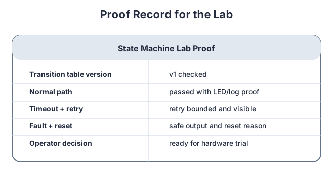
Use a compact record:
Lab: ESP32 state-machine check
Transition table version: v1
Implementation: event queue + dispatch loop
Normal path tested: yes
Invalid sample path tested: yes
Ack timeout retry path tested: yes
Retry exhausted path tested: yes
Wrong-state event handling tested: yes
Reset/persistence policy checked: yes
Open issue: define which restart causes should resume as FAULT
Decision: ready for hardware trial after open issue is closed
12.16 Knowledge Check
12.17 Common Pitfalls
- Starting with code instead of the table: the table is the contract that makes the implementation checkable.
- Doing work in guards: guards should decide; actions should change hardware, context, timers, or proof.
- Ignoring wrong-state events: every important event should be handled, rejected, deferred, or logged deliberately.
- Saving too much state: persistence should restore only safe context and should record reset reason.
- Testing only the happy path: most state-machine bugs appear in timeout, retry, reset, and invalid-event paths.
12.18 Overview: The Lab Proves The Contract
The ESP32 lab is not finished when the firmware compiles or the normal LED sequence works. It is finished when the transition table, implementation, and test record all describe the same behavior. The table says what should happen, the code performs it, and the proof record shows that each important path was exercised.
This matters because state-machine bugs often hide outside the happy path. A button press in the wrong state, a timeout during transmit, a reboot during pending work, or a retry counter that never stops can all pass a simple demonstration while still failing in the field.
In this lab, treat the ESP32 board as a source of explicit events rather than as a bundle of callbacks. Button A publishes EV_SAMPLE_REQUEST, Button B publishes EV_ACK_RECEIVED, a sensor failure publishes EV_SAMPLE_INVALID, and the timer publishes EV_TIMEOUT. The state machine decides what each event means from the current state.
A traceable run should show more than final LED color. It should show the transition row used, the guard result, any context changes such as retry_count, the next state, and the output that proves the state changed. For example, a timeout in TRANSMIT with retries left should increment the retry count and retransmit; the same timeout at the limit should enter FAULT and stop radio work.
The overview test is therefore simple: another person should be able to read the table, run the event sequence, and explain why the device accepted, rejected, or deferred each event. If the behavior depends on a hidden variable or callback side effect, the lab has not proved the contract yet.
The lab should also name what is intentionally out of scope. If radio encryption, cloud delivery, or long-term storage is not part of the state-machine test, keep those details outside the proof record. The record should stay focused on event handling, transitions, outputs, faults, and reset behavior.
12.19 Practitioner: Build The Lab Proof Record
Record proof while the lab runs, not after memory fades. A useful lab record lets another developer reproduce the decision and see which behavior is still unproven.
Start the record from the transition table version and the firmware build identifier. Then add one row for each normal, invalid, timing, retry, reset, and wrong-state behavior that matters to the lab. Each row should name the exact input event, starting state, guard value, action, next state, visible output, and proof source. That keeps the record connected to the design instead of becoming a loose checklist.
Use one row per meaningful behavior, not one row per button press. A normal path row can cite the sequence IDLE + EV_SAMPLE_REQUEST -> SAMPLE, SAMPLE + EV_SAMPLE_READY -> TRANSMIT, and TRANSMIT + EV_ACK_RECEIVED -> IDLE. A fault row should separately cite invalid sample, sample timeout, acknowledgement timeout with retry allowed, acknowledgement timeout at the limit, and reset while recovery is denied.
For hardware runs, pair serial logs with visible output. If an LED indicates FAULT, the log should also name the fault reason and retained context. If a reset returns to IDLE, the record should say whether the reset was manual, watchdog, brownout, or power-cycle, because those reset causes may have different safe restore policies.
The practitioner check is complete when every row has an expected proof source: serial line, LED state, persisted reset reason, retry counter, queued message identifier, or explicit rejected-event log. Rows without proof are design assumptions, not lab results.
Before closing the lab, mark any untested row as an open issue with an owner. A skipped timeout, overflow, or reset path should not be treated as passed just because the normal demo worked.
Transition Proof
For each tested row, record the source state, event, guard result, action, next state, output, and visible log line.
Rejected Event Proof
Record wrong-state events, invalid events, queue overflow, duplicate acknowledgements, and the reason each one was ignored, rejected, or deferred.
Recovery Proof
Record reset cause, restored context, retry count, fault reason, safe output, and the guard that allowed or denied return to normal operation.
A compact serial log is enough if it is structured. For example, TRANSMIT + Timeout + retry_count=2 -> FAULT + radio_off + fault=ack_timeout is a better proof artifact than “timeout tested.”
12.20 Event Queues Change Risk
An event queue protects the state machine from doing heavy work inside callbacks, but it also introduces ordering and capacity risk. Two events can arrive before the main loop dispatches either one. An acknowledgement can arrive after a timeout was already queued. A full queue can silently drop the event that would have moved the device to a safe state.
That is why the lab should test queue order, queue overflow, duplicate events, and stale events explicitly. The state machine should not assume the event stream is clean. It should prove what happens when events arrive late, early, twice, or in the wrong state.
On an ESP32-style system, the queue boundary is also a concurrency boundary. GPIO interrupts, timer callbacks, Wi-Fi or ESP-NOW callbacks, and sensor completion callbacks may occur while the main loop is still processing an older event. The callback should capture only the event type and minimal context, then return quickly. The dispatch loop should own state transitions, context mutation, and hardware actions.
Queue capacity needs a policy. Dropping the newest event may be acceptable for repeated button presses, but it is risky for FAULT or TIMEOUT events. Dropping the oldest event may preserve the latest fault but erase the acknowledgement that would close a pending transmission. The lab should name the policy and include one test where the queue fills.
Event freshness is the other under-the-hood check. An acknowledgement should carry enough context, such as a message id or command age, so the state machine can reject a stale acknowledgement after a timeout transition. Without that check, a late acknowledgement can clear the wrong retry state and make the proof record misleading.
The dispatch loop should also define atomic context updates. If the state changes to FAULT, the fault reason, retry count, pending message id, and output update should be recorded as one transition outcome. Splitting those updates across callbacks can leave the proof log describing a state the device never safely reached.
12.21 Summary
This lab turns an ESP32-style firmware task into a checkable state machine. The transition table defines the behavior before code is written. The event queue keeps asynchronous inputs manageable. Guards, actions, timeouts, persistence, and fault recovery become explicit paths. The final test matrix and proof record show whether the behavior was actually verified.
12.22 Key Takeaway
A state-machine lab should prove behavior under normal events, faults, resets, timing edges, and recovery before the model is trusted.
12.23 See Also
- State Machine Fundamentals for IoT: the core concepts used in this lab.
- State Machines in IoT: applying the pattern across device, gateway, and cloud workflows.
- Microcontroller Programming Essentials: firmware loop and GPIO foundations.
- Production Architecture Management: readiness records and operational handoff.
12.24 What’s Next
Continue to State Machines in IoT to connect the lab pattern to larger IoT workflows, or return to State Machine Fundamentals for IoT if you need to refine the transition table before implementation.