5 Setpoint, Error, and Feedback
5.1 Start With One Feedback Loop
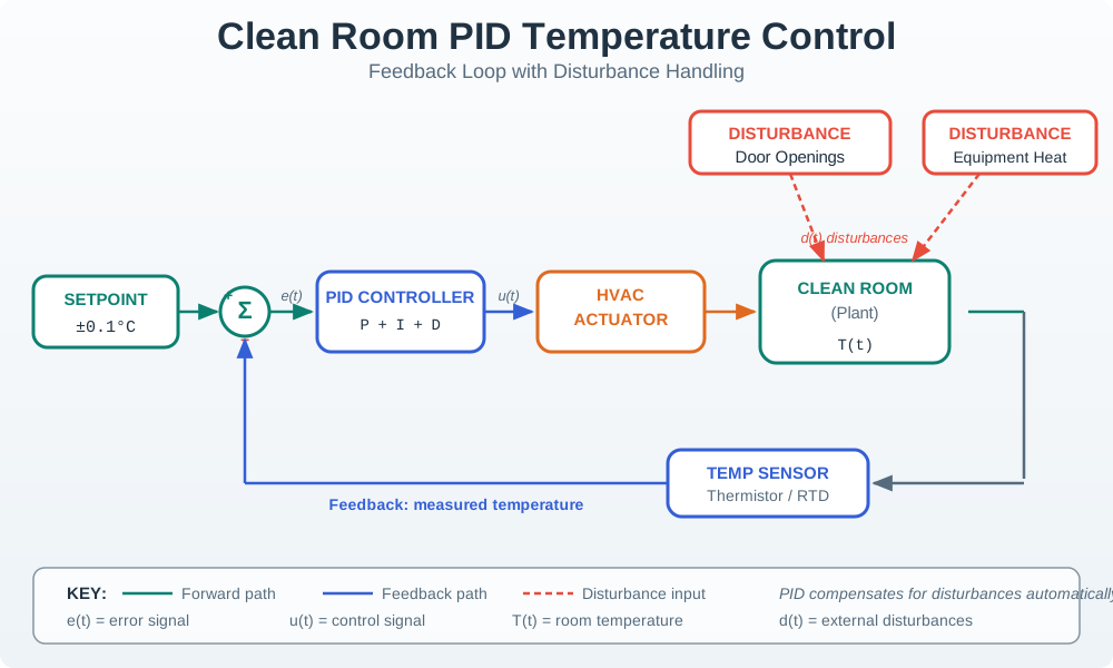
Feedback is the moment a device stops guessing and listens to the result of its own action. A heater turns on, the room warms, the sensor reports the change, and the controller decides whether to keep pushing or back off.
That loop is everywhere in IoT: irrigation valves, fans, chargers, robots, and gateways all need evidence that the last command helped. Start with the setpoint, the measurement, and the error; every feedback pattern in the chapter is a variation on that small loop.
5.2 Learning Objectives
By the end of this chapter, you should be able to:
- Define setpoint, process variable, error signal, controller output, actuator, and disturbance.
- Explain why negative feedback is the standard regulation pattern for PID control.
- Distinguish regulation feedback from positive feedback used for switching or latch behavior.
- Decide whether a feedback loop should run locally, remotely, or as a hybrid with local fallback.
- Build a feedback loop record that names the loop purpose, proof, fallback, and recheck trigger.
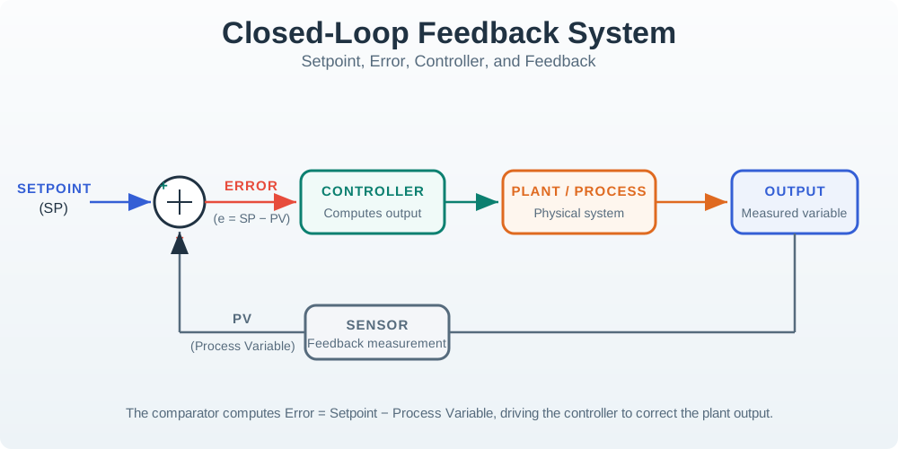
The overview depth layer below carries the feedback loop map that connects target, error, controller action, actuator command, process response, sensor evidence, and fallback proof.
5.3 Where This Chapter Fits
Feedback fundamentals explain the control loop that PID builds on. Later PID chapters can discuss open-loop comparison, proportional action, integral action, derivative action, implementation details, and tuning. This chapter keeps the focus on the loop vocabulary and the proof a team needs before trusting any controller.
Inputs
Controlled variable, target setpoint, sensor measurement, actuator path, disturbance sources, and required fallback behavior.
Outputs
Feedback vocabulary, loop placement decision, negative or positive feedback choice, and a reusable feedback loop record.
Loop-Fit Habit
Ask, “What measured output changes the next command, and what happens if that measurement or command path fails?”
5.4 Feedback Vocabulary
A feedback loop is easier to check when each responsibility has a plain name.
| Term | Meaning | Loop Question |
|---|---|---|
| Setpoint | The target value the loop is trying to maintain or reach. | Who owns the target, and when is it allowed to change? |
| Process variable | The measured output that tells the controller what the system is doing. | Is the sensor measuring the right physical quantity with enough confidence? |
| Error signal | The difference between the setpoint and measured process variable. | Is the error sign, unit, and scaling clearly documented? |
| Actuator output | The command sent to the device that can change the process. | What limits, fail-safe state, and manual override apply? |
| Disturbance | An outside influence that changes the process without being commanded by the controller. | What disturbances must the loop detect and recover from? |
The Essential Equation
For a basic loop check, the feedback question can stay simple:
error = setpoint - measured_process_variable
next_action = controller(error, limits, fallback_state)
The exact controller can be on/off, proportional, PI, PID, or another policy. The feedback requirement is that measured output affects the next action.
5.5 Negative and Positive Feedback
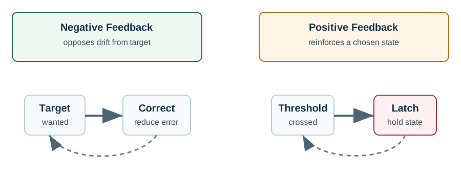
The most important feedback distinction is whether the action reduces or reinforces a change.
| Feedback Type | What It Does | Where It Fits | Main Risk |
|---|---|---|---|
| Negative feedback | Opposes the measured error so the process moves back toward the target. | Temperature, pressure, speed, flow, level, position, and other regulation loops. | Poorly chosen gain, delay, or sensor filtering can still cause oscillation. |
| Positive feedback | Reinforces a state change so the system switches decisively. | Threshold switching, latches, alarms, hysteresis, and state selection. | Used accidentally in a regulation loop, it can run away from the target. |
PID Connection
PID is a negative feedback controller. Proportional, integral, and derivative terms all use the error signal to reduce deviation from the setpoint. If a PID loop appears to amplify error, check sign convention, actuator direction, sensor scaling, and wiring before tuning gains.
5.6 Local and Distributed Feedback
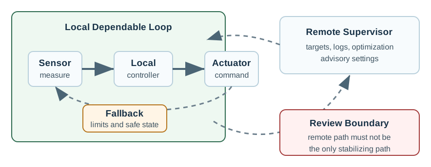
Many IoT systems split measurement, decision-making, and commands across devices and services. That can be useful for supervision and optimization, but it can also make the feedback loop depend on a path that is not always available.
| Placement Pattern | Good Use | Loop Proof |
|---|---|---|
| Local feedback | The process needs dependable response even when the network path is unavailable. | Local sensor path, actuator command path, limits, manual override, and fallback state are documented. |
| Remote coordination | The remote side changes schedules, targets, reports, or optimization settings but does not carry the only safety path. | The local loop keeps operating with last approved settings or a safe fallback. |
| Hybrid feedback | Local control handles direct response while remote logic supervises trends and policy. | Ownership is clear for local limits, remote target changes, stale commands, and recovery after reconnection. |
Fallback Rule
If losing the network path would leave the actuator unable to respond to a harmful or service-breaking condition, the loop needs local fallback. Remote logic can advise, tune, schedule, or report, but the basic stabilizing behavior must remain available where the sensor and actuator are connected.
5.7 Feedback Timing and Trust Addendum
A feedback loop can fail even when the controller equation is correct. The loop record should prove that measurement arrives soon enough, represents the right process variable, and still deserves trust when the system is degraded.
| Loop item | Proof to preserve |
|---|---|
| Loop roles | Target or band, measurement, comparison, correction, actuator path, process response, and verification proof. |
| Timing chain | Sample delay, filtering or network delay, controller decision delay, actuator delay, process response, and verification delay. |
| Placement | Local loop for fast or safety-relevant correction, edge coordination for nearby shared limits, remote supervision for history and approved setpoints. |
| Measurement trust | Sensor placement, calibration, plausibility checks, stuck-value detection, missing samples, filtering delay, and diagnostic proof. |
| Failure modes | Wrong sign, stale proof, actuator limit, noisy signal, network loss, and the fallback state used instead of continuing blindly. |
| Recheck trigger | Sensor move, actuator replacement, process change, repeated alarm, setpoint-policy change, or network-path redesign. |
Use this addendum before tuning. A loop is ready for PID work only after the measured value demonstrably changes the next action and the fallback behavior is bounded when proof is untrustworthy.
5.8 Feedback Loop Record
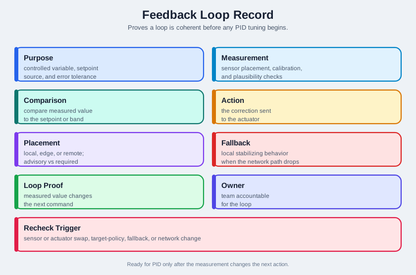
A feedback loop is not ready for PID tuning until the loop record proves that the loop itself is coherent.
Purpose
Name the controlled variable, the setpoint source, and the error tolerance that matters to the system.
Loop Proof
Show that the measured value changes the next command and that the command can actually influence the process.
Placement
Document what runs locally, what runs remotely, what is advisory, and what is required for dependable operation.
Recheck Trigger
Recheck the loop after sensor replacement, actuator replacement, target-policy change, fallback change, or network-path redesign.
5.9 Knowledge Check
5.10 Match Feedback Terms to Loop Proof
5.11 Order a Feedback Decision
5.12 Common Pitfalls
Feedback Without a Real Actuator Path
A dashboard that only displays measurements is monitoring, not closed-loop control. Feedback requires a command path that can influence the process.
Reversed Error Sign
If the actuator moves in the wrong direction, the loop can amplify the problem. Always verify sign convention and actuator direction before tuning.
Remote Logic as the Only Control Path
Remote optimization is useful, but a critical loop should not lose basic regulation just because the network path is unavailable.
Treating Positive Feedback as Regulation
Positive feedback can be valid for switching and hysteresis, but it is not the normal pattern for holding a process near a target.
5.13 Overview: Feedback Needs A Proof Path
A feedback loop is real only when a measured value changes the next action. A dashboard can show temperature, pressure, or speed, but the loop is not closed until that measurement is compared with a setpoint and drives an actuator command that can change the process.
The practical question is simple: if the process drifts right now, where is the measurement, where is the decision, where is the actuator, and what proof shows the action reduced the error instead of making it worse?
Mobile summary: A feedback loop is trustworthy only when the measurement changes a correctly directed actuator command and the fallback state is bounded.
5.14 Feedback Trust Record
Before tuning a controller, write down what the loop is allowed to trust. This record prevents teams from tuning gains around a stale measurement, reversed sign, missing command path, or remote dependency that cannot survive an outage.
| Trust Item | Evidence To Record | Failure If Missing |
|---|---|---|
| Measurement | Sensor placement, units, calibration, plausibility checks, missing-sample behavior, and timestamp. | The controller reacts to a value that may not represent the process. |
| Comparison | Setpoint owner, error sign, scaling, target band, and allowed setpoint changes. | The loop can drive away from the target or chase the wrong target. |
| Action | Actuator path, output limits, fail-safe state, manual override, and command acknowledgement. | The decision may not be able to affect the physical process. |
| Placement | Local fallback, remote advisory role, stale-command rule, and reconnection behavior. | A network outage can silently open the feedback loop. |
5.15 Delay and Sign Set Stability
Negative feedback works because the action opposes error. If the sign is reversed, the same loop becomes positive feedback and pushes the process farther from the target. If delay is too large, even correctly signed action can arrive after the process has moved on.
That is why feedback proof includes timing, not only wiring. The loop has sensor delay, filtering delay, controller decision time, network delay when remote, actuator delay, and process response time. A stable local loop can become unstable if the decision is moved across a slow or unreliable path.
The under-the-hood check is to prove direction and timing before tuning: the actuator must move the process in the correcting direction, and it must do so soon enough for the process being controlled.
5.16 Summary
Feedback is the foundation for PID control. The loop measures a process variable, compares it with a setpoint, computes error, and changes an actuator command. Negative feedback reduces error and is the normal regulation pattern. Positive feedback reinforces state changes and belongs only in deliberate switching behavior. In IoT systems, feedback quality depends not just on the controller equation but also on sensor proof, actuator limits, placement, fallback, ownership, and recheck triggers.
5.17 Key Takeaway
Feedback loops need deployment proof: define the measured variable, setpoint, actuator, delay, disturbance, and safe response before tuning gains.
5.18 See Also
5.19 What’s Next
Continue with Open-Loop and Closed-Loop Systems to compare systems that act from fixed commands with systems that close the loop through measurement and correction.