4 PID Control Theory
4.1 Start With the Error You Can Measure
A PID controller does not begin with three magic constants. It begins with a gap between what you want and what you can measure: temperature below a setpoint, tank level above a limit, or motor speed drifting away from target.
The proportional, integral, and derivative terms are three different answers to that gap. For an IoT device, the useful story is not “use PID” but “measure error, choose the correction, and prove the loop settles safely.” Start with one measured error before tuning anything.
4.2 Learning Objectives
By the end of this chapter, you should be able to:
- Explain the PID control equation without treating it as a black box.
- Describe how proportional, integral, and derivative actions change loop behavior.
- Identify steady-state offset, overshoot, oscillation, windup, and derivative noise sensitivity.
- Choose P, PI, PD, or PID based on response data rather than habit.
- Create a control-loop decision record that connects theory to implementation risk.
The overview depth layer below carries the loop map that connects setpoint, error, PID action, bounded output, sensor feedback, and review evidence.
4.3 Where This Chapter Fits
This chapter focuses on the theory behind the PID controller. Later chapters can tune gains, implement code, and evaluate applications; this one explains what the terms mean and what teams must check before those implementation choices are trusted.
Inputs
Setpoint, measured process variable, actuator limits, sample interval, sensor noise, disturbance behavior, and loop-safety requirements.
Outputs
Term roles, configuration choice, stability cautions, proof questions, and a reusable control-loop decision record.
Loop-Fit Habit
Ask, “Which term is solving which observed loop problem, and what new risk does that term introduce?”
4.4 PID Equation
The continuous-time PID idea can be written in implementation-friendly form:
error = setpoint - process_variable
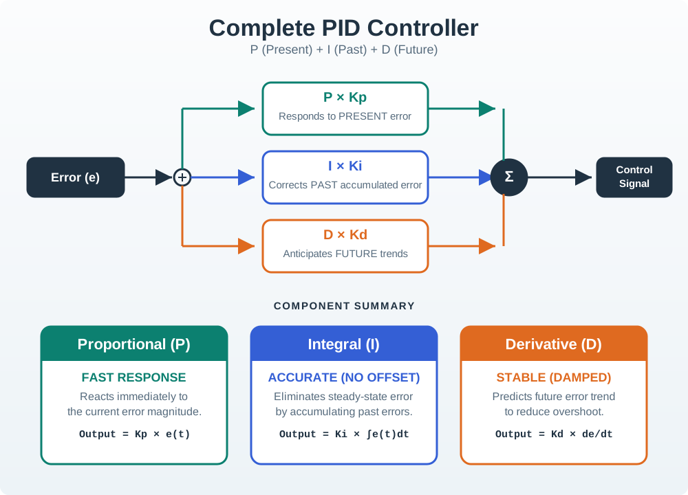
output = Kp * error + Ki * error_sum + Kd * error_rate
In that expression:
Kpscales the instantaneous error.Kiscales the accumulated error.Kdscales the rate of error change.outputdrives an actuator, valve, motor, heater, fan, pump, or other control element.
Theory-to-Implementation Check
The equation is not complete until the loop record also names sample interval, output limits, integral limit, derivative filtering, and what happens when the actuator cannot follow the requested output.
4.5 Term Behavior
The three terms can be understood as three views of the same error signal.
| Term | Responds To | Primary Benefit | Main Risk |
|---|---|---|---|
| Proportional | Instantaneous error magnitude. | Fast correction that moves the process toward the setpoint. | Too much gain can overshoot or oscillate; too little gain can leave offset. |
| Integral | Error that persists over repeated samples. | Removes steady-state offset caused by load, bias, or disturbance. | Can wind up when the actuator saturates or the process cannot respond. |
| Derivative | Error trend or rate of change. | Adds damping and can reduce overshoot. | Amplifies measurement noise unless filtered and sampled carefully. |
4.6 Signal and Term Selection Addendum
Most PID selection mistakes start as signal or term-selection mistakes. Define the loop signals before tuning, then enable only the terms that solve an observed control problem.
| Loop area | Proof to record |
|---|---|
| Signal names | Setpoint or target band, process variable, error sign convention, controller output, manipulated variable, and sample period. |
| Proportional baseline | P-only response, acceptable offset, overshoot or oscillation trace, and actuator output remaining inside limits. |
| Integral decision | Persistent offset, holding-command need, actuator saturation risk, accumulator limit, anti-windup policy, and recovery behavior. |
| Derivative decision | Overshoot or ringing trace, measurement quality, filter choice, setpoint-kick handling, and sample-rate justification. |
| Mode choice | P, PI, PD, or PID selected from observed symptoms rather than from controller feature availability. |
| Loop proof log | P/I/D contributions, saturation state, filtered derivative path, output clamp, outcome trace, owner, and recheck trigger. |
For example, a fan speed loop with a stable P-only response but persistent load offset justifies PI plus an accumulator limit. Derivative action should wait until overshoot or ringing is visible and the measurement can support a useful rate estimate.
4.7 Reading Response Shape
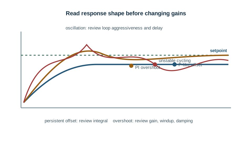
PID theory becomes practical when a team can look at a response shape and connect it to a term decision.
Persistent Offset
If the process settles away from the setpoint, proportional action may not be enough. Integral action can remove the offset, but only if windup is controlled.
Overshoot
If the process crosses the target too aggressively, reduce excessive gain, check integral buildup, or add derivative damping when the measurement is clean enough.
Oscillation
If the process cycles around the target, the loop may be too aggressive, delayed, undersampled, poorly filtered, or limited by actuator behavior.
4.8 Configuration Choice
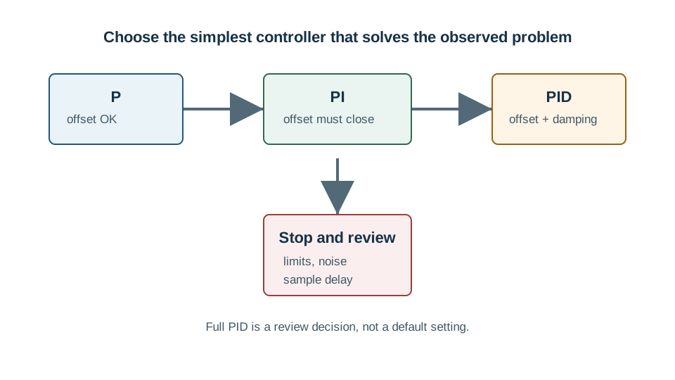
Use the simplest controller that solves the observed loop problem with acceptable risk.
| Configuration | When It Fits | Proof Needed |
|---|---|---|
| P | The process tolerates some offset and needs a simple proportional response. | Stable response, acceptable offset, and actuator output inside limits. |
| PI | Offset must be removed and the process is slow enough that derivative damping is not needed. | Integral limit, anti-windup behavior, and disturbance recovery trace. |
| PD | Overshoot must be damped but persistent offset is acceptable or handled elsewhere. | Filtered derivative path, noise check, and sample-rate justification. |
| PID | Offset, overshoot, and disturbance response all need active control. | Term-by-term tuning record, saturation check, noise filter, and safety bounds. |
4.9 Windup and Derivative Filtering
Two PID theory mistakes show up repeatedly in IoT and process-control reviews.
Integral Windup
When an actuator is already at its limit, the integral term may keep accumulating error. When the process finally responds, the stored integral can drive a large overshoot. Check clamping, conditional integration, or reset behavior.
Derivative Noise
Derivative action magnifies rapid measurement changes. A noisy sensor can make the controller output jitter unless derivative filtering, sensor filtering, and sample timing are checked together.
4.10 Control-Loop Decision Record
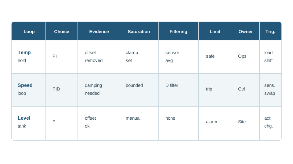
A PID loop record keeps theory, tuning, implementation, and proof connected.
Record Template
- Loop goal: What setpoint and process variable define success?
- Controller choice: P, PI, PD, or PID, with the observed problem it addresses.
- Term proof: What response data justifies each enabled term?
- Limits: Output bounds, integral bounds, actuator saturation, and fail-safe state.
- Filtering: Sensor filtering, derivative filtering, and sample interval.
- Owner and trigger: Who rechecks the loop after sensor, actuator, load, or timing changes?
4.11 Process-System PID Addendum
PID is a system decision before it is a tuning exercise. Keep the process boundary, placement, and output limits visible so the controller does not hide unsupported assumptions inside gain values.
| Loop item | Proof to keep |
|---|---|
| System placement | Local loop, edge coordination, or remote supervision, with proof that required correction is not stranded behind an unreliable path. |
| Loop signals | Setpoint, process variable, error sign, controller output, actuator command, sample period, and measurement validity. |
| Mode selection | P, PI, PD, or PID chosen from observed offset, overshoot, measurement quality, actuator limits, and recovery behavior. |
| Limits and protection | Output clamp, saturation flag, anti-windup rule, derivative filtering, manual mode, and fail-safe state. |
| Tuning proof | Baseline trace, changed term, disturbance check, command range, settling behavior, and the decision to keep, reject, or repeat. |
For a tank-level or ventilation loop, start with the simplest defensible mode. Add integral only when persistent offset matters and anti-windup is defined; add derivative only when damping is needed and the measurement can support a useful rate estimate.
4.12 Knowledge Check
4.13 Match PID Theory to Loop Proof
4.14 Order a PID Theory Decision
4.15 Common Pitfalls
Starting With Full PID
Enabling all three terms before proving which loop problem each term solves makes tuning harder and hides root causes.
Treating the Equation as Enough
The equation does not document sample timing, actuator limits, filter choices, windup behavior, or safety fallback.
Ignoring Saturation
A controller designed as if actuators can follow every requested output may fail badly when real devices hit limits.
Unfiltered Derivative Action
Derivative gain can turn ordinary sensor noise into control chatter when the measurement path is not filtered.
4.16 Overview: PID Terms Are Evidence Claims
A PID setting is not just a number. Each enabled term is a claim about the loop: proportional action claims the current error needs immediate correction, integral action claims persistent offset must be removed, and derivative action claims the trend needs damping.
The useful habit is to connect each term to an observed response shape and to the risk it introduces. A controller that reaches the setpoint once is not fully proved until saturation, noise, disturbance, sampling, and recovery behavior have also been checked.
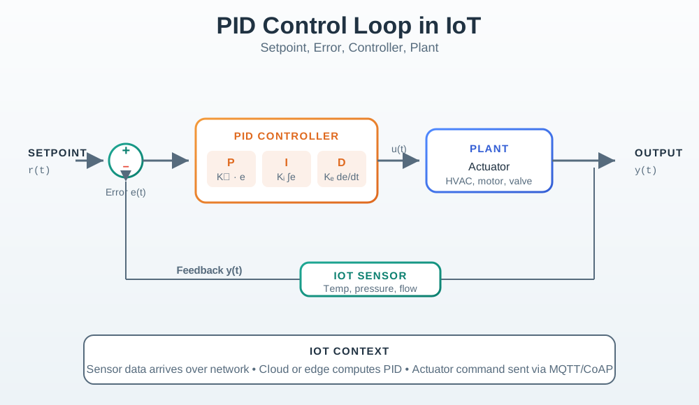
Mobile summary: Keep each PID term only when the response evidence, actuator limits, sensor quality, and recovery behavior support the loop goal.
4.17 Term Proof Record
Before keeping a PID configuration, record what each term is solving and what guardrail keeps that term from causing a new failure.
| Term | Keep It When | Guardrail To Prove |
|---|---|---|
| P | The response moves toward the setpoint without unacceptable overshoot or cycling. | Gain, output clamp, acceptable offset, and response after a small disturbance. |
| I | Persistent offset matters and the actuator has enough authority to correct it. | Accumulator limit, anti-windup behavior, saturation flag, and recovery trace. |
| D | Overshoot or ringing needs damping and the measurement is clean enough. | Derivative filter, sample-rate reason, noise test, and setpoint-kick handling. |
4.18 Sampled and Limited Loops
Real PID controllers run at a sample interval and drive a limited actuator. That means the neat equation hides practical state: the previous error, accumulated error, filtered derivative estimate, output clamp, saturation flag, manual/auto mode, and sensor validity.
Those states explain why a gain set that works in one trace can fail later. A slower sample interval can make derivative action stale. A saturated actuator can make integral action store a command the process cannot follow. A noisy sensor can turn derivative gain into output chatter.
The under-the-hood check is to compare requested control action with what the actuator, sensor, and process can actually support over time.
4.19 Summary
PID control theory explains how feedback action is built from proportional, integral, and derivative terms.
- Proportional action scales instantaneous error.
- Integral action removes persistent offset but needs windup protection.
- Derivative action adds damping but needs noise and sampling review.
- Controller choice should follow observed response shape and loop risk.
- A loop record should connect the equation to proof, limits, filtering, ownership, and recheck triggers.
4.20 Key Takeaway
PID theory becomes useful when proportional, integral, and derivative choices are tied to field behavior, actuator limits, noise, sampling, and recovery proof.
4.21 See Also
4.22 What’s Next
Continue with PID Feedback Fundamentals to connect PID terms back to feedback-loop behavior and loop stability concepts.