12 E1: Link-Layer Encryption
Hop-by-Hop Wireless Protection, Key Scope, and Blast Radius
E1 link-layer encryption, hop-by-hop encryption, link key scope, blast radius, frame counter, replay protection, AES-CCM link security
12.1 Protect One Local Hop, Then Name the Next Reader
E1 is encryption at the link or MAC layer: it protects a single wireless hop between two directly adjacent devices, such as a sensor and a nearby router, a peripheral and a central, or a device and a local gateway. When E1 is enabled, a frame on the air is encrypted and carries an integrity check, so a nearby attacker cannot casually read it and a tampered frame is rejected.
The most important thing to understand about E1 is that it is hop-by-hop, not end-to-end. The next node that receives the frame decrypts it, reads the contents, and then forwards the message onward, often re-protecting it on the next hop with a different key. That node, a router, border router, bridge, or gateway, sees the plaintext. This is expected behaviour, not a bug, but it means E1 by itself does not keep data private once it passes the first trusted receiver.
If you only need the intuition, this layer is enough: E1 protects the local radio hop against nearby eavesdropping and frame tampering, but the node that terminates it reads the plaintext. E1 is good local access control; it is not end-to-end privacy, it is not proof of a specific application identity, and a shared link key can spread one compromise widely.
Think of a relay of couriers, each carrying a locked pouch one stretch of road. Each courier unlocks the pouch at the end of their leg, reads the note, then locks it in a fresh pouch for the next courier. The road is safe between stops, but every courier at a handover sees the message. E1 secures the stretches of road; it does not seal the note from the couriers who relay it.
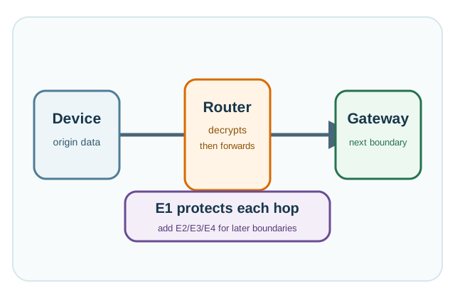
The One-Minute View
Protects the local hop
An encrypted, integrity-checked frame stops nearby eavesdropping and rejects tampered or injected frames on the radio link.
Hop-by-hop, not end-to-end
The node that terminates the link decrypts and reads the data. Name every node that decrypts, and add an upper layer where it must not.
Key scope sets the blast radius
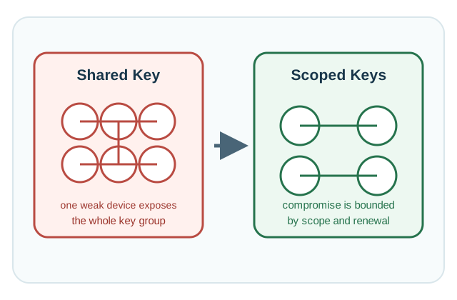
A shared network key lets one extracted device expose the whole group. Scoped, pairwise, or session keys contain a compromise.
Beginner Examples
- A smart-home device on an encrypted local mesh is safe from a neighbour sniffing the air, but the hub that receives its frames reads every value before sending them to the cloud.
- “Link encryption is on” does not say who holds the key. If every sensor in a building shares one network key, one stolen sensor can expose the others’ traffic.
- A captured valid command can be replayed unless the receiver checks a frame counter or packet number and rejects an old frame before acting on it.
Overview Knowledge Check
If you can explain that E1 protects a hop and that the terminating node reads the plaintext, you can stop here. Continue to Practitioner to review key scope, frame evidence, and when to add another layer.
12.2 Review the Hop, Key Scope, and Replay Proof
An E1 review should never stop at “encryption is enabled.” The job is to map which nodes decrypt, name the key scope and the blast radius it creates, capture frame-level evidence, and prove that tampered and replayed frames are rejected. The most common finding is a shared network key that quietly turns one device’s compromise into a group-wide exposure.
Walkthrough: Reviewing an E1 Link
- Map every hop and decryptor. List each local hop and each node, router, bridge, or gateway, that terminates link security and therefore reads plaintext.
- Name the key scope. State whether the key is network-wide, group, pairwise, or session-scoped, and judge whether that scope matches the data’s sensitivity.
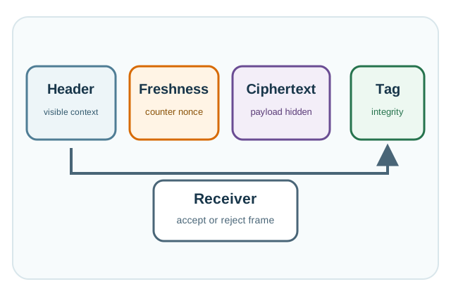
- Capture frame evidence. Record the visible header, the freshness field, the ciphertext, and the integrity tag, using key identifiers and fingerprints, never raw keys.
- Run negative tests. Confirm that a tampered ciphertext, a tampered authenticated header, a wrong-key frame, and a replayed old frame are all rejected before any application action.
- Decide on upper layers. Where a gateway must not read the data, or the blast radius is too large, add E2 per-device keys, E3 object protection, E4 transport, or E5 renewal.
Key Scope and Blast Radius
The central E1 design risk is rarely the cipher; it is key scope. The broader the scope, the more traffic one extracted key exposes. Match the scope to the sensitivity of the data and the resources of the device.
Worked Review: A Warehouse Sensor Mesh
A warehouse runs a low-power mesh of door, motion, and environmental sensors with E1 enabled, and a gateway forwards events to the cloud. The team says “the mesh is encrypted, so we are covered.” The reviewer turns that into findings.
What E1 delivers here
Packet captures show ciphertext and an integrity tag on local frames, and replayed old frames are rejected, so casual eavesdropping and simple replay are handled.
What the review uncovers
The gateway logs decrypted event fields, and many sensors share one network key, so a gateway compromise or one extracted sensor exposes a broad set of traffic.
Conclusion
Keep E1 enabled, but add E2 or E3/E4 protection for sensitive event fields, segment the key scope toward per-device keys, and document the rekey and quarantine process before release.
Practitioner Knowledge Check
If you can map decryptors, judge key scope, and prove replay rejection, you can stop here. Continue to Under the Hood for the frame mechanics, the counter-reset hazard, and what link authenticity does and does not prove.
12.3 Frame Counters Make the Hop Trustworthy
The deeper layer explains how a protected link frame is built, why a freshness counter is a correctness condition rather than a detail, and why E1 authenticity is weaker than application identity. Each is an independent guarantee, and the link cipher’s strength cannot rescue a reset counter or an over-broad key.
How a Protected Link Frame Is Built
Modern link security is authenticated encryption: it pairs encryption of the payload with a message integrity check so a modified frame is rejected. Many IoT link layers use an AEAD construction such as AES-CCM for this. A protected frame typically has four parts: a visible header that must stay readable for routing but is authenticated as associated data so it cannot be changed silently; a freshness value such as a frame counter or packet number; the encrypted payload; and an integrity tag. The receiver recomputes the tag over the header and ciphertext and rejects the frame if it does not match, before passing anything to the application. Protocols including Bluetooth Low Energy, IEEE 802.15.4 meshes, Wi-Fi, and LoRaWAN each define their own profile of these parts.
Freshness, Counters, and the Power-Loss Hazard
That freshness field is what blocks replay, and it doubles as the per-frame nonce for the AEAD. The rule is the same as for any authenticated mode: a counter or nonce must never repeat under the same key. This is where a classic IoT failure appears. If a device loses power, restarts, and resumes counting from a low value while keeping the same link key, it reuses nonces, which can leak the relationship between payloads and undermine the integrity guarantee. Safe designs persist the counter across resets in non-volatile storage, or force a rekey on rejoin so a fresh key starts a fresh counter. A review should test exactly this: capture a baseline frame, confirm the counter advances, then power-cycle and confirm the device does not reuse old values.
What Link Authenticity Does and Does Not Prove
E1 proves that a frame came from a device holding the link key, which is not the same as proving it came from a specific authorized application identity, especially when the key is shared across many nodes. If the receiver needs to know which device or which application sent a command, it needs per-device keys (E2) or an application-layer signature, not just a valid link tag. Two related hazards follow. A temporary join, install, or commissioning secret must not quietly become an indefinite fleet-wide credential; the design should show the transition from join material to scoped operational keys. And visible headers used for routing may still need authentication, because a receiver that trusts unauthenticated metadata can be steered by an attacker who rewrites it.
When E1 Is Enough, and When It Is Not
E1 is a sound local access-control layer: it raises the bar against nearby eavesdroppers and casual frame injection. It is sufficient on its own only for low-sensitivity data on a hop where every terminating node is trusted to read it and the key scope is acceptable. It is not enough when data must stay private past a gateway (add E3 object protection or E4 transport), when sender identity must be specific (add E2 per-device keys), or when a shared key’s blast radius is too large (narrow the scope and add E5 renewal). The architecture decision is always layered against the trust boundaries, not a single switch.
Mechanisms and Failure Modes
Common Pitfalls
- Treating E1 as end-to-end. The terminating node reads plaintext; name every decryptor and add an upper layer where it must not read.
- Counter reset after power loss. Reusing old freshness values under the same key breaks the link AEAD; persist the counter or rekey on rejoin.
- Over-broad key scope. A shared network key spreads one compromise across the group; prefer pairwise or session keys for sensitive traffic.
- Link key as application trust. A valid link tag proves key possession, not a specific sender; use E2 or application signatures when identity matters.
- Commissioning key left in place. A join or install secret must transition to scoped operational keys, not become a permanent fleet credential.
- Unauthenticated metadata. Visible headers that influence the receiver’s decision must be authenticated, not merely transmitted.
Under-the-Hood Knowledge Check
At this depth, E1 is a set of independent guarantees on one local hop: an authenticated frame, a freshness counter that never repeats per key, an authenticated header, a key whose scope bounds the blast radius, and a named map of every node that decrypts. Get those right and E1 is solid local access control, but reserve end-to-end privacy and specific sender identity for the upper layers built on top of it.
12.4 Summary
- E1 is link-layer (MAC-layer) encryption that protects one local wireless hop between adjacent nodes against nearby eavesdropping and frame tampering.
- E1 is hop-by-hop, not end-to-end: the node that terminates the link decrypts and reads the plaintext, which is expected but must be named in the design.
- A protected frame pairs encryption with an integrity tag (often AES-CCM), authenticates the visible header as associated data, and uses a freshness counter as the per-frame nonce.
- The freshness counter blocks replay and must never repeat under one key; a counter reset after power loss reuses nonces and breaks link security.
- Key scope sets the blast radius: a shared network key makes one extraction a group-wide exposure, while pairwise or session keys contain it.
- E1 authenticity proves possession of the link key, not a specific application identity; use E2 per-device keys or signatures when the sender must be identified.
- Add E2, E3/E4, or E5 when data must stay private past a gateway, when sender identity matters, or when the shared-key blast radius is too large.
Link-layer encryption is useful local access control, but it is not end-to-end trust. Name every node that decrypts the hop, keep the freshness counter unique per key across reboots, narrow the key scope to bound the blast radius, and add transport or application protection when data crosses gateways or networks you do not fully control.
12.5 See Also
Encryption Architecture and Levels
See where E1 sits in the full E1-E5 model of trust boundaries and plaintext ownership.
Device-to-Gateway Encryption (E2)
Shrink the shared-key blast radius with per-device keys, message integrity, and replay protection.
Symmetric Encryption
Revisit the AEAD modes and the nonce-uniqueness rule that link-layer security depends on.