3 Classical Control Architectures for Mobile Robots
3.1 Overview: Put Every Controller on Two Axes
Before applying the specification, inspect the real industrial robot installation below: its package, terminals, scale, and installation context are part of the engineering evidence.
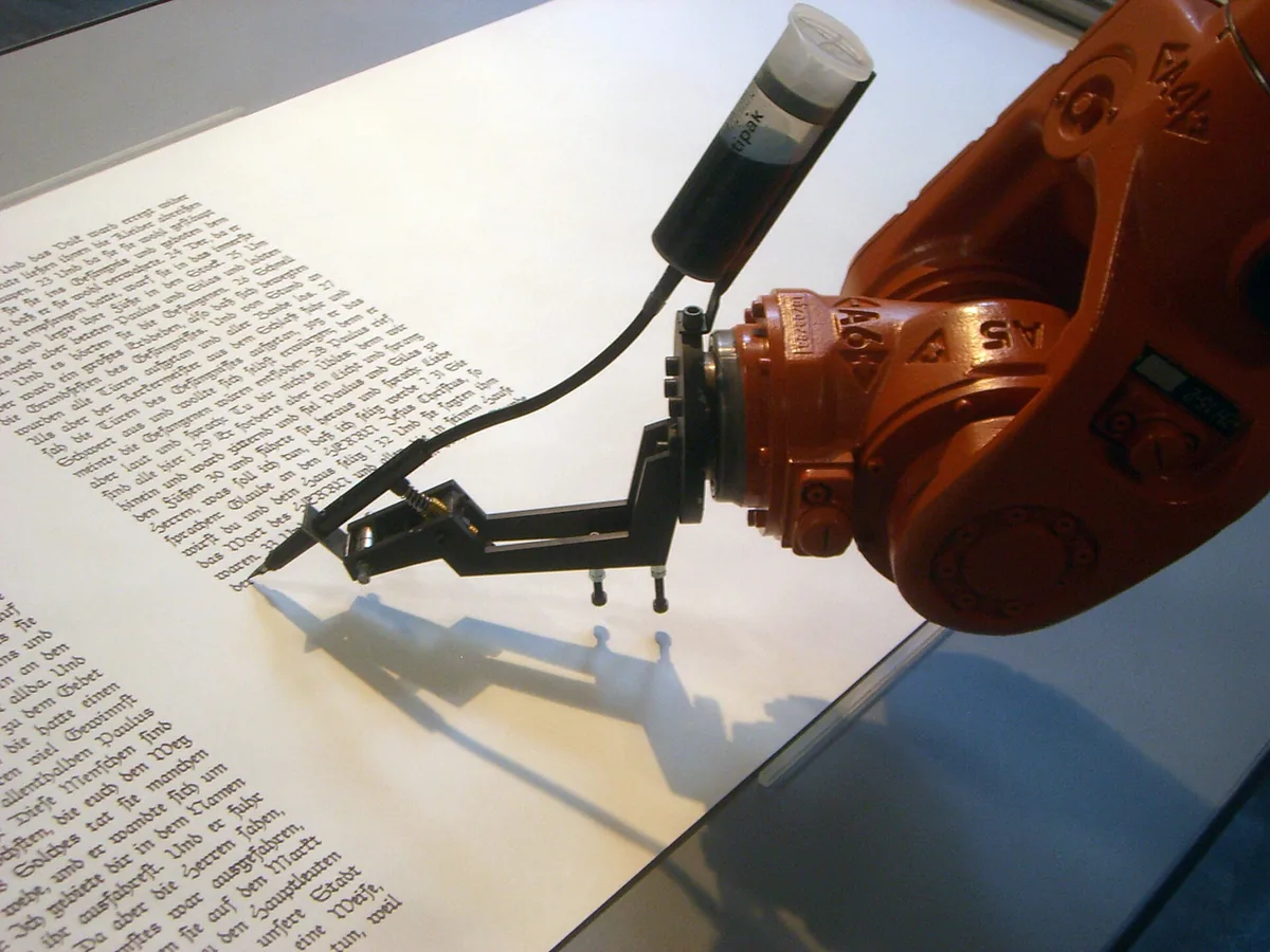
Carry those visible constraints into the surrounding analysis; the abstract symbol or capability name does not capture mounting, wiring, protection, or service access.
You already know one classical robot controller. A Braitenberg vehicle wires sensed intensity to motor response, producing behavior without a map or explicit plan. This chapter does not re-teach that mature treatment. It places Braitenberg’s proximal, reactive design inside a wider architecture map and then compares the paradigms around it.
The source lecture classifies robot control along two axes:
- Sensing distance: proximal versus distal. A proximal controller operates close to sensor input. A distal controller assembles named behavioral blocks such as avoid-obstacle, follow-wall, or move-to-goal.
- Planning horizon: reactive versus deliberative. A reactive controller applies time-invariant rules to its current world estimate. A deliberative controller predicts future states and plans an action sequence that minimizes a metric such as collision risk, energy, or path length.
The axes are independent. “Reactive” does not mean “unstructured,” and “distal” does not automatically mean “deliberative.” A motor-schema controller can combine named behaviors at every cycle without planning minutes ahead.
3.1.1 Architecture Is a Latency and Evidence Decision
-
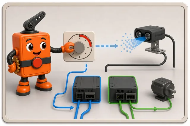
Set the shortest safe delay before choosing the robot control design.
-
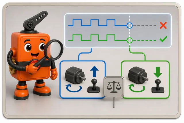
Compare which choices an operator can inspect when actions disagree.
-
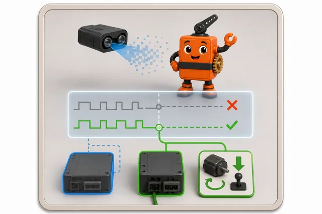
Test a stale sensor and keep only a design that reaches a safe state.
Choose the architecture from the control contract, beginning with the shortest permitted delay between sensing a hazard and changing the motor command. That latency budget determines whether a local reflex must remain in the immediate control path or whether a planner has time to compare future trajectories. Next decide which internal decisions an operator must be able to inspect: named behaviors and explicit arbitration expose different evidence from a compact sensor-to-motor mapping.
Then test disagreement and failure. If avoid-obstacle and move-to-goal request incompatible commands, the design must state whether priority, suppression, vector composition, or a safety supervisor wins. If a range sensor becomes stale or implausible, the same contract must say which commands remain permitted and what brings the robot to a safe state. These questions are more useful than asking which paradigm is “most intelligent.” A controller that misses the stopping-time budget or cannot reveal why an unsafe command won is wrong even if it produces a sophisticated plan.
3.2 Practitioner: Build Behaviors, Then Define Their Arbitration
The simplest inspectable reactive controller is a rule set:
if left proximity sensors are active:  turn right
if right proximity sensors are active: turn left
if no proximity sensors are active:    move forward
The pseudocode hides the most important implementation question: what happens if both left and right sensors are active? Production rules need explicit priority, mutual exclusion, timeouts, and a safe default. Otherwise source order becomes accidental arbitration.
3.2.1 Potential Fields: Add Local Forces
In the potential-field paradigm associated with Khatib (1986), the goal contributes an attractive vector and obstacles contribute repulsive vectors. The command follows their sum:
The method is compact and naturally reactive. Its characteristic failure is a local minimum: forces can cancel at a point that is not the goal. Narrow passages can also make repulsion dominate the useful forward component. A defensible implementation records a stuck detector and an escape policy instead of treating the summed vector as guaranteed progress.
3.2.2 Motor Schemas: Compose Named Behaviors
Motor schemas, associated with Arkin (1989), turn behaviors into modules with explicit meanings. A warehouse robot might combine:
move-to-pickup: points toward the task goal;avoid-obstacle: pushes away from range detections;keep-clearance: maintains aisle-wall distance;stop-on-stale-perception: overrides motion when evidence expires.
Composition can be weighted, gated, or priority based. Whatever the mechanism, the weights and overrides are part of the safety argument. A silent numeric sum is not an operational policy until you can explain which behavior wins and why.
3.2.3 Subsumption: Let Higher Layers Suppress Lower Ones
Subsumption architecture, associated with Brooks (1986), stacks behaviors so a higher layer can suppress or inhibit a lower layer while preserving the lower layer as a working fallback.
Explore
Select new space to visit when lower-level safety and motion remain available.
Avoid obstacles
Suppress forward exploration when clearance evidence crosses the hazard threshold.
Maintain motion safety
Stop or limit actuators when perception is stale, drivers saturate, or a hard limit opens.
The stack makes priority visible. It also creates a test obligation: verify every suppression edge, including recovery when the higher-priority condition clears.
3.3 Lab: Interrupt-To-Actuator Feedback Loop
Build the smallest closed loop that exposes every timing and safety boundary. A digital sensor interrupt records an edge and timestamp. The interrupt handler does not drive the motor; it places a compact event in a bounded handoff slot. The control task consumes the newest valid event, computes a bounded command, updates a motor driver or an LED stand-in, and records the input time, decision time, output time, saturation state, and failsafe reason.
// Interrupt top half: no logging, allocation, delay, or motor command.
void sensor_isr(void) {
  pending_edge = true;
  edge_time_us = monotonic_us();
}

// Control bottom half: one explicit owner of actuator state.
void control_step(void) {
  if (sensor_stale() || watchdog_expired() || driver_fault()) {
    motor_command(0);       // neutral / de-energized safe state
    led_alarm(true);
    record_failsafe();
    return;
  }
  command = clamp(kp * (setpoint - measurement), -MAX_CMD, MAX_CMD);
  motor_command(command);
  record_timing(edge_time_us, monotonic_us(), command);
}
Use the LED first so an incorrect output cannot move hardware. Then connect a current-limited motor driver with an independent enable and emergency stop. Inject a stuck-high sensor, missing sensor events, an overrun, a driver fault, and a reset. Every fault must produce the declared safe state without depending on the dashboard, network, or a future sensor update.
The acceptance record contains the wiring diagram, interrupt source and edge policy, debounce rule, control period, command clamp, motor-driver electrical limits, LED stand-in result, four timing markers, watchdog owner, stale threshold, safe output state, and recovery authority. The lab passes only when normal feedback is observable and every injected fault reaches the same bounded failsafe.
3.4 Under the Hood: From Weighted Neurons to Safe Arbitration
A small neural reactive controller maps sensor inputs into each neuron’s activation:
The source example uses and connects eight sensor inputs to two motor outputs. The architecture is proximal: learned or selected weights operate close to readings. It is reactive when the current input vector alone determines the current output.
The transfer function bounds each neuron output, but it does not by itself bound the physical command. A safe deployment still needs output scaling, rate limits, saturation handling, stale-input behavior, and tests at the corners of the sensor domain.
3.4.1 One Corridor, Four Architectures
Consider a robot moving toward a loading bay while a pallet blocks part of the aisle.
Neural reactive
Range readings pass through weighted connections to left and right motor outputs. Inspect the domain coverage and command bounds.
Rule based
Named sensor conditions select turn or stop actions. Inspect overlap, priority, and hysteresis.
Potential field
Goal attraction and pallet repulsion produce a direction vector. Inspect local minima and narrow-passage behavior.
Subsumption
Obstacle avoidance suppresses goal seeking while the hazard exists. Inspect suppression, release, and fallback transitions.
The scenario has not changed; only the controller’s representation and arbitration have. That makes cross-architecture tests possible: run the same sensor traces and physical limits through each design, then compare stopping distance, command continuity, recoverability, and evidence clarity.
3.4.2 Failure Contracts by Architecture
| Architecture | Evidence to log | Characteristic failure to test | Safe response |
|---|---|---|---|
| Neural reactive | normalized inputs, output activation, saturation flags | unseen or extreme input combinations | clamp command and fall back to a bounded behavior |
| Rule based | matched rules and winning priority | overlapping or uncovered conditions | deterministic safe default |
| Potential field | component vectors and summed magnitude | local minimum or oscillation | stuck detector and escape mode |
| Motor schema | behavior outputs, weights, gates | unsafe weight interaction | safety schema override |
| Subsumption | active layer and suppression edges | layer that never releases or suppresses incorrectly | timeout, explicit reset, lower-layer fallback |
Architecture selection is therefore an observability decision too. If an incident review cannot reconstruct why the controller issued a command, the system lacks a usable control record even when the motion looked correct.
3.5 Summary
Classify a controller in two passes: first locate its distance from raw sensing, then identify how far it reasons into the future. That separation prevents a named behavior from being mistaken for a plan and keeps the engineering review focused on the path from evidence to motor command. The comparison also exposes the real trade: fast local response, inspectable composition, predictive capability, and safe arbitration must fit the same physical timing envelope.
- Proximal versus distal describes distance from raw sensing; reactive versus deliberative describes planning horizon.
- Neural and Braitenberg controllers can create fast proximal reactions, while rules and motor schemas expose named behaviors.
- Potential fields compose attractive and repulsive vectors but can become trapped in local minima.
- Subsumption makes behavioral priority explicit through suppression and inhibition between layers.
- Every architecture needs a physical command envelope, observable arbitration, and tested failure recovery.
3.6 Key Takeaway
The best control architecture is the one whose latency, arbitration, and failure behavior you can state and test. Name how sensing becomes action, how conflicts are resolved, and what takes control when the evidence is unsafe.
3.7 See Also
Continue according to the boundary you need to examine. Revisit kinematics when the issue is whether a requested command is physically feasible, and use the Braitenberg material when the sensor-to-motor transfer itself needs inspection. PID control supplies the actuator-level feedback beneath an architecture, while the multi-robot chapter extends arbitration and evidence flow beyond one platform. Together, these links move outward from individual signals to mechanisms, controllers, and coordinated teams.
- Mobile Robot Kinematics and the Perception-Action Loop — the motion and feedback contract these architectures control.
- Braitenberg Vehicles — a mature proximal/reactive controller with hands-on examples.
- Braitenberg Transfer Functions — how sensor-to-motor mappings change emergent behavior.
- PID Control Theory — classical closed-loop feedback at the actuator/process level.
- Multi-Robot Systems: Taxonomy, Estimation, and Coordination — the next chapter extends control from one robot to a networked team.