3 Processes and Systems Thinking
3.1 Start With the System Boundary
A process only becomes controllable when its boundary is clear. Before choosing a sensor, dashboard, or controller, ask what enters the system, what leaves it, what state changes inside it, and who is responsible when the change crosses an edge.
That plain boundary view is the starting point for everyday IoT work: pumps, heaters, conveyors, alerts, and gateways all fail in confusing ways when the team cannot say where the process ends. Start with one input, one output, and one state change, then build the system model around that proof.
3.2 Learning Objectives
By the end of this chapter, you will be able to:
- Distinguish systems, processes, boundaries, interfaces, inputs, and outputs.
- Draw input-process-output block diagrams for IoT devices and services.
- Decompose an IoT solution into device, network, edge, and remote service responsibilities.
- Place feedback and control choices in context without treating them as the whole design.
- Build a process-and-system decision record that supports later debugging, upgrades, and chapter routing.
3.3 Overview: Start With the Boundary
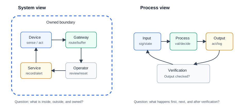
If you only need the intuition, this layer is enough: a system is the owned boundary, and a process is the ordered change inside or across that boundary. IoT design becomes easier to inspect when the team can say what enters, what changes, what leaves, and who owns each crossing.
System question
What components, services, people, and responsibilities are inside the design boundary?
Process question
What sequence turns inputs into outputs, state changes, alerts, actions, or records?
Interface question
What signal, command, data, power, material, or human handoff crosses the boundary?
Evidence question
What observation proves that the output happened and that fallback behavior is owned?
For a cold-room monitor, the system boundary includes the door sensor, temperature measurement, local controller, message path, dashboard, and alert owner. The process is the ordered path from a door-open input to validation, alarm decision, message delivery, maintenance action, and proof that the door returned to normal.
That distinction keeps a team from treating a dashboard message as the whole system. A door reed switch, thermistor or RTD, ESP32 or PLC input, gateway, MQTT message, dashboard alarm, and staff acknowledgement can all be part of one system. The process record explains which step validates the reading, which step starts the open-door timer, which step sends the alert, and which step proves someone acted.
The boundary should also name what is outside the design. If building power, a cloud notification service, or a human response team is a dependency rather than an owned block, the record should say so. That makes fallback decisions visible before a late outage or staffing change exposes them.
When the boundary is explicit, later chapters have a stable starting point: feedback discusses correction, networking discusses delivery, and operations discusses response without changing the original promise.
3.4 Practitioner: Build the Decision Record
A process-and-system record should be small enough to keep current, but specific enough that another engineer can replay the decision. Start with one operating promise, then write down the boundary and the outputs that prove the promise.
1. Name the promise
Example: warn staff when a cold-room door remains open long enough to threaten product quality.
2. Draw the owned boundary
Include the sensor, controller, local alarm, gateway path, dashboard, recipient, and maintenance record.
3. Trace the process
Show reading, validation, timer, alarm rule, message send, acknowledgement, service action, and close-out record.
4. Define fallback
State what happens when the network, dashboard, alert recipient, power source, or sensor reading is unavailable.
Reject records that only say “use an IoT gateway” or “send data to the cloud.” Those labels do not prove input trust, process ownership, output verification, or degraded behavior.
A useful record reads like a replayable incident trace. For the cold-room example, it can say that door_open=true starts a timer only after the input passes freshness and range checks, that a local alarm sounds after the allowed duration, that the gateway buffers an MQTT event if the WAN is down, and that the dashboard state is not accepted as resolved until a maintenance note or acknowledgement closes the loop.
Keep the record short, but make each field testable. The boundary field should list owned blocks and excluded responsibilities. The interface field should name signal, power, data, mechanical, service, and human handoffs. The fallback field should say whether the system continues locally, queues records, enters a safe state, or asks for manual intervention.
Review it after each meaningful change. A different sensor position, alarm threshold, gateway firmware, notification service, or staffing model can change the process even when the block diagram still looks familiar. The record should make that comparison routine rather than political.
3.5 Why Boundary Failures Spread
The deeper layer explains why process-and-system thinking prevents late-stage surprises. Most IoT failures are not isolated to one component. A wrong sensor assumption can create a bad control decision, a missing gateway buffer can erase evidence, and an unclear alert owner can turn a correct measurement into an unresolved incident.
- Input trust: a sensor value needs calibration, freshness, range, and validity checks before a process can rely on it.
- State ownership: timers, retries, buffers, manual overrides, and fallback states must belong to a named block.
- Output proof: a message sent by a device is not the same as an action completed by an operator, actuator, or service.
- Change impact: moving a sensor, gateway, placement boundary, target threshold, or alert workflow can invalidate the original record.
Boundary failures spread because neighboring blocks often make assumptions without owning the evidence. If a gateway assumes the controller already filtered stale readings, it may forward bad data as a valid incident. If the dashboard assumes an alert means staff responded, it may hide an unresolved local problem. If the controller assumes the gateway will always be reachable, it may skip the local alarm path exactly when connectivity fails.
Use small checks to expose those assumptions. Test the sensor input with missing, stale, noisy, and moved-sensor cases. Test the timer and alarm rule without the dashboard. Test the gateway buffer with WAN loss and recovery. Test the close-out record with a real acknowledgement path. The integrated process should then prove the same ownership chain in order.
This is also why decomposition matters. A block that owns validation should not also silently own operator response. A block that owns delivery should not rewrite the business meaning of the alert. Keeping those responsibilities separate makes defects local enough to diagnose.
Core concept: A system names what is inside the boundary. A process names what happens over time to transform inputs into outputs.
Why it matters: Most IoT failures are boundary failures: the wrong input is trusted, an interface is unclear, an output is not verified, a process depends on a missing service, or nobody owns the fallback state.
Key takeaway: Start with a block diagram and a decision record. Then choose sensors, actuators, communication paths, feedback loops, and controller details from the measured process need.
3.6 Prerequisites
Before this chapter, revisit:
- IoT Reference Models: layered responsibility models and architecture vocabulary.
- Feedback Mechanisms: how measurement becomes correction.
- Open vs Closed Loop: when feedback is needed.
- Process Control and PID: how process behavior leads into controller selection.
3.7 System, Process, Boundary, and Interface
A system view answers “what is included?” A process view answers “what happens next?” Both are needed because the same IoT product can be described as physical equipment, firmware, messages, services, support workflow, or a control loop.
System
A bounded collection of components, people, services, and interfaces that work together for a purpose.
Process
An ordered transformation of material, energy, information, state, or commands into an intended result.
Boundary
The line that separates what the design owns from its environment, dependencies, operators, and external services.
Interface
The contract where signals, power, data, physical movement, messages, or responsibilities cross a boundary.
3.8 Input-Process-Output Thinking
A useful first diagram names the inputs, the process that transforms them, and the outputs that should be produced or verified. Inputs can be physical, electrical, informational, or human. Outputs can be actions, data, alerts, material movement, state changes, or records.
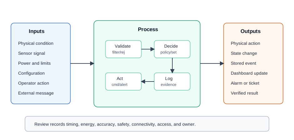
- Inputs: sensor readings, commands, configuration, power, materials, environmental conditions, and operator actions.
- Process: filtering, validation, decision logic, communication, actuation, logging, escalation, and fallback behavior.
- Outputs: physical action, stored data, messages, dashboard state, alarms, reports, and records that the result was checked.
- Constraints: timing, energy, memory, safety, connectivity, accuracy, maintenance access, and ownership boundaries.
3.9 Block Diagrams
Block diagrams are useful because they hide implementation detail while preserving responsibility and flow. The goal is not to draw every wire. The goal is to make the important boundaries, interfaces, and dependencies visible enough for a decision.
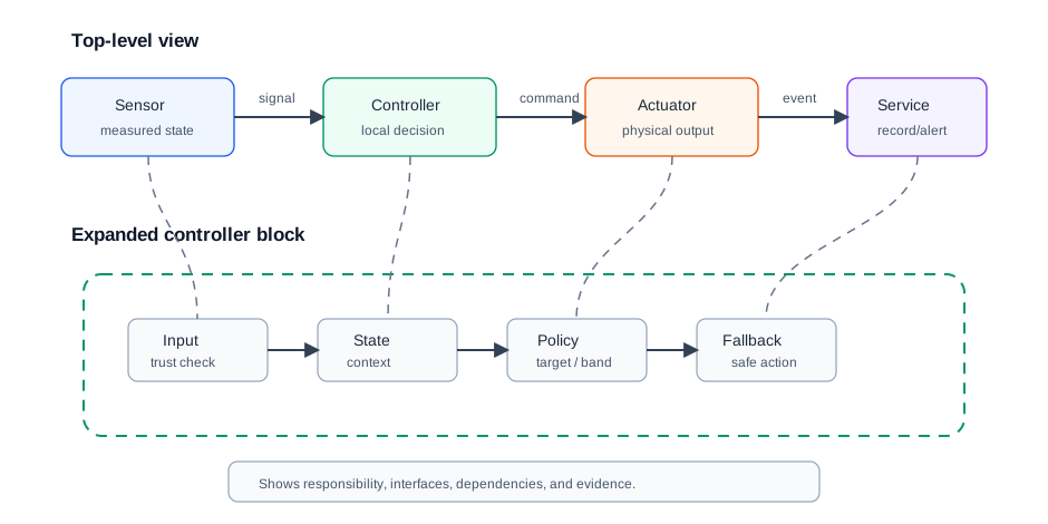
Good block diagrams answer these questions:
- What does each block own?
- What crosses each interface?
- Which input is trusted, filtered, or rejected?
- Which output is verified?
- Which dependency can stop the process?
- Where does the design enter fallback or manual intervention?
3.10 Decomposing an IoT System
Hierarchical decomposition helps teams discuss a system at the right level. A device engineer, network engineer, service owner, operations team, and learner may all need different views of the same design.
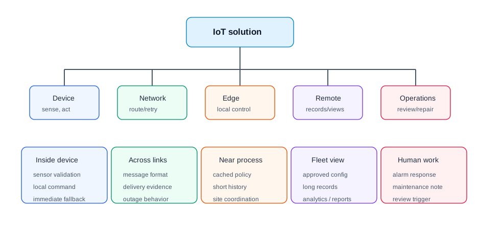
Device responsibility
Sensing, local validation, actuation, power state, local logs, and immediate fallback behavior.
Network responsibility
Connectivity, protocol translation, retries, buffering, routing, and message-delivery records.
Edge responsibility
Local coordination, cached policy, short-term history, nearby equipment limits, and outage-tolerant decisions.
Remote responsibility
Long-term records, dashboards, fleet comparison, approved configuration, alerts, analytics, and reporting.
3.11 Where Feedback Fits
Feedback is one process pattern inside a larger system. A feedback loop measures an output, compares it with a target or band, and corrects the next action. The system still needs boundaries, interfaces, trust checks, and fallback behavior.
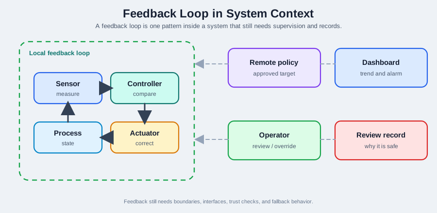
Feedback context should identify:
- The controlled variable and where it is measured.
- The target, band, or policy that defines the intended state.
- The actuator and whether it has enough authority to correct the process.
- The loop timing from measurement to verified response.
- The safe behavior when measurement, actuation, or communication is unreliable.
3.12 Decision Records
Process-and-system decision records make design choices reusable. They also help the next maintainer understand why a block diagram, interface, placement choice, or fallback rule was accepted.
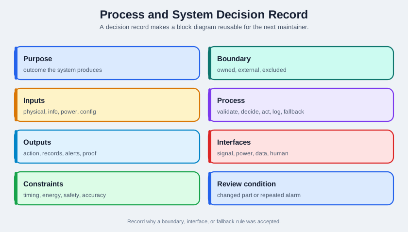
Process-and-system decision
Purpose: what outcome the system exists to produce
Boundary: owned components, outside dependencies, and excluded responsibilities
Inputs: physical, informational, power, configuration, and operator inputs
Process: validation, decision, communication, actuation, logging, fallback
Outputs: physical action, messages, records, alerts, and verification proof
Interfaces: signal, power, data, mechanical, service, and human handoff points
Constraints: timing, energy, safety, accuracy, connectivity, support, maintenance
Review condition: changed sensor, actuator, process, placement, target, or repeated alarm
3.13 Learning Route
This chapter orients the series. Use the route below to choose the next chapter based on the question you are trying to answer.
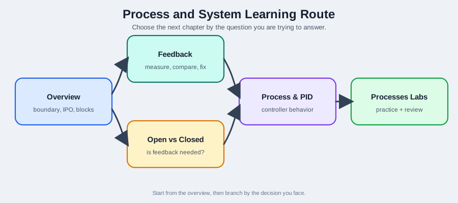
Need loop vocabulary?
Use Feedback Mechanisms to study measurement, comparison, correction, and verification.
Choosing open or closed loop?
Use Open vs Closed Loop to decide whether feedback is needed.
Choosing controller behavior?
Use Process Control and PID before moving into detailed controller chapters.
Need practice?
Use Processes Labs after the system boundary and loop proof are clear.
3.14 Fundamentals Route Addendum
Use the overview as the entry point for a stable decision sequence. Keep system vocabulary separate from process vocabulary and control vocabulary so later feedback and PID choices have a clear basis.
| Decision step | Record to capture |
|---|---|
| Core definitions | Purpose, boundary, environment, inputs, transformation, outputs, retained state, constraints, interfaces, assumptions, and review conditions. |
| Input-process-output | What enters, what changes, what leaves, what state is retained, and which constraints shape acceptable behavior. |
| Block diagram | Responsibility of each block, meaning of each interface, trusted inputs, verified outputs, dependencies, and fallback points. |
| Decomposition | Device, communication, site or edge, remote service, and operator workflow responsibilities. |
| Feedback need | Whether the system must measure the result before choosing the next action. |
| Control complexity | Open-loop, on/off feedback, proportional-family, or PID choice made only after measurement trust, actuator authority, timing, and fallback are clear. |
This route prevents premature labels. A design is not closed-loop because it has a sensor, and it is not PID because it has a variable output. The record should show the measurement, comparison, command, output limit, and fallback behavior before the control label is accepted.
3.15 Cold-Room Door Monitoring
A cold-room monitoring system reports door state, temperature trend, and equipment alarms. A process-and-system overview does not start by choosing a controller. It starts by naming boundaries and flows.
System boundary: door sensor, room-temperature measurement, local controller, power supply, message path, remote dashboard, alert recipient, and maintenance record.
Process: sense the door state, validate the reading, compare against allowed open duration, record the event, alert if the condition persists, and verify that the door returned to normal.
Interfaces: sensor wiring or radio link, controller input, local storage, gateway or network path, alert channel, and maintenance handoff.
Fallback: if remote connectivity is unavailable, the local controller should keep recording events and use the local alarm path if the condition remains unresolved.
The same system can later be inspected as a feedback loop, an alerting workflow, a networked gateway pattern, or an operations record. The overview diagram keeps those later views grounded.
3.16 Knowledge Check
3.17 Match the Overview Concepts
3.18 Order a Process-and-System Decision
Key Concepts
- System: A bounded collection of components, services, people, and responsibilities that work together for a purpose.
- Process: An ordered transformation of inputs into outputs, state changes, records, alerts, or physical action.
- Boundary: The line that defines what the design owns and what remains external.
- Interface: The point where signals, power, data, motion, messages, or responsibility cross a boundary.
- Block diagram: A simplified representation of responsibility, flow, and dependency without unnecessary implementation detail.
- Decomposition: Breaking a system into smaller responsible blocks so each interface and failure mode can be checked.
- Decision record: The proof that preserves why a system boundary, process, interface, or fallback decision was accepted.
Common Pitfalls
Starting with code instead of boundaries
Implementation becomes hard to check when nobody knows what the system owns or which process each block supports.
Drawing every wire too early
A block diagram should expose responsibilities and flows first. Low-level wiring belongs in a later implementation view.
Ignoring output verification
An output is not trustworthy until the design says how it is checked, logged, or escalated.
Hiding dependencies
External services, human actions, network paths, and maintenance records are still part of the system behavior.
Confusing feedback with the whole system
Feedback is one process pattern. The system also needs interfaces, ownership, constraints, and fallback behavior.
Leaving no review condition
Sensor moves, actuator changes, new targets, placement changes, and repeated alarms can invalidate the original diagram.
3.19 Summary
Process-and-system thinking gives IoT design a stable starting point. Define the system boundary, list inputs and outputs, trace the process, draw block diagrams at the right abstraction level, decompose responsibilities, and record constraints and fallback behavior. Feedback, open-loop choices, and controller design become clearer once the system view and process flow are explicit.
3.20 See Also
- Feedback Mechanisms: measurement, comparison, correction, and verification.
- Open vs Closed Loop: when feedback is required.
- Process Control and PID: controller choice from process behavior.
- Processes Labs: practicing process decisions with verification records.
- Edge and Fog Computing: placing responsibilities near the physical process.
3.21 What’s Next
Continue with Feedback Mechanisms if you need loop vocabulary, or use Open vs Closed Loop to decide whether a process should be scheduled, feedback-based, or hybrid.