This appendix is a quick-reference companion for IoT terminology, protocol comparisons, sensor specifications, ESP32 pin assignments, common unit conversions, engineering formulas, and standards links. Use it when you already understand the topic and need to recall a fact quickly. Return to the detailed chapters when you need design reasoning, implementation guidance, or troubleshooting context.
Start with the section heading that matches the fact you need.
Use the tables for quick comparison, not as a substitute for full design trade-off analysis.
Check the formulas and calculators when you need a first-pass estimate.
Follow standards links when exact protocol behavior or compliance language matters.
Treat examples here as reference patterns that still need adaptation for your hardware and project constraints.
8.2 Start With The Evidence Note
Use the appendix like a bench card, not like an answer key. A table can remind you that a pin is input-only, a protocol uses a certain transport, or a battery formula needs current and time. The project still needs an evidence note that says where the value came from, which design decision depends on it, and what check would catch a wrong assumption.
For example, a range row becomes useful only after you attach band, antenna, enclosure, mounting, walls, interference, and field RSSI or SNR. A sensor row becomes useful only after you attach calibration, warm-up, mounting, airflow, supply voltage, and drift. A formula becomes useful only after you write the units and compare the estimate with a measurement.
Start every lookup with three short lines: reference, requirement, evidence. That habit keeps quick facts from turning into hidden design risks.
8.3 Learning Objectives
By using this appendix, you will be able to:
Locate definitions for acronyms and technical terms used throughout the curriculum.
Compare reference tables to assess trade-offs among different IoT technologies.
Interpret common sensor parameters while justifying design decisions.
Apply networking, electronics, and battery-life formulas to first-pass engineering estimates.
Trace IEEE, IETF, and industry specifications when authoritative protocol documentation is needed.
8.4 References Are Not Requirements
The appendix is a bench reference, not a decision engine. A table can remind you that IEEE 802.11 normally gives higher throughput than IEEE 802.15.4, that MQTT uses publish/subscribe over TCP, that CoAP is specified by IETF RFC 7252, or that ESP32 GPIO 34-39 are input-only on common boards. Those facts are useful because they shorten recall. They are unsafe when they are copied into a design without the condition that made the fact true.
Use every lookup as the first line of an evidence note. A wireless range row needs frequency band, transmit power, antenna gain, enclosure, installation height, walls, interference, duty-cycle rules, and field RSSI or SNR. A sensor accuracy row needs operating range, calibration, mounting, airflow, self-heating, supply voltage, and drift. A protocol row needs the exact specification version, packet behavior, security profile, broker or server configuration, and failure mode that the project will tolerate.
The safest mental model is reference, requirement, evidence. The reference gives a value or definition. The requirement says how your project depends on it. The evidence proves the dependency with a datasheet revision, standard clause, packet capture, bench measurement, calculator input, or field test. Without all three, a lookup can sound precise while hiding the real engineering assumption.
Lookup Type
What It Can Tell You
What It Cannot Prove Alone
Evidence To Attach
Protocol row
Transport, message pattern, QoS, overhead, and common use
That the chosen device, broker, gateway, or network handles the failure case
Treat appendix values as entries in a reference ledger: fact, dependency, evidence, and the next check that would falsify the assumption.
8.5 Convert Lookup Into Evidence
When you use this appendix during a build, convert the lookup into a short evidence card before the value enters a capstone report, firmware constant, schematic, or dashboard. Start with the exact fact and its source location. Then name the project dependency: battery sizing, link margin, storage retention, sensor threshold, broker behavior, pin assignment, regulatory channel plan, or maintenance workflow. Finally, write the next check that would catch a wrong assumption.
For protocols, attach the specific standard or implementation behavior. MQTT may mean OASIS MQTT 3.1.1 or MQTT 5.0; QoS 1 still allows duplicates, so a telemetry pipeline needs message identifiers, timestamps, or idempotent writes. CoAP comes from RFC 7252, but retransmission timers, confirmable messages, DTLS, OSCORE, proxy behavior, and UDP loss still need project-level review. 6LoWPAN relies on adaptation over IEEE 802.15.4, so MTU, fragmentation, route repair, and border-router behavior belong next to the table row.
For hardware, attach the exact device and board context. ESP32 pin references are only safe after the board schematic, boot strapping pins, input-only pins, ADC limitations, I2C pull-ups, and peripheral conflicts are checked. A BME280 or SHT31 row should lead to interface wiring, address setting, enclosure airflow, sampling interval, self-heating, and calibration expectations. A PMS5003 particulate sensor row should lead to airflow, warm-up, cleaning, and replacement planning rather than a single accuracy claim.
For formulas, keep inputs and units visible. A link-budget estimate should name transmit power, antenna gain, receiver sensitivity, path-loss model, installation height, cable loss, regional limit, and field RSSI/SNR target. A battery estimate should include active current, sleep current, wake interval, radio burst length, regulator quiescent current, battery chemistry, temperature, self-discharge, and end-of-life margin. The formula is the traceable arithmetic; the evidence card is the engineering argument.
A good appendix note is short enough to write during lab work: “Reference fact, project dependency, source revision, measured or calculated proof, unresolved risk, owner, date.” That format lets another teammate repeat the lookup and challenge the design without rereading the whole module.
8.6 Specifications Leave Implementation Gaps
Under the hood, many appendix facts come from standards or datasheets that deliberately stop at an interface boundary. IEEE 802.11 and IEEE 802.15.4 define radio and MAC behavior, but they do not decide antenna placement, enclosure losses, channel congestion, power policy, or application recovery. IETF RFCs such as RFC 7252 for CoAP, RFC 6550 for RPL, RFC 4944 and RFC 6282 for 6LoWPAN define protocol mechanisms, but a product still chooses timers, buffer sizes, routing policy, security credentials, and observability.
Datasheets draw similar boundaries. A microcontroller technical reference manual can describe ADC resolution, touch channels, UARTs, SPI controllers, I2C controllers, boot pins, and absolute maximum ratings. It cannot prove that a particular dev board exposes the pin safely, that a sensor cable has enough pull-up strength, that a relay module will not drag a boot strap pin, or that Wi-Fi activity will not disturb an analog measurement. A sensor datasheet may quote accuracy under controlled calibration conditions while your enclosure creates heat, dust, condensation, vibration, or airflow constraints.
Formula references also leave gaps. Free-space path loss assumes a simplified propagation model; indoor multipath, body absorption, metal cabinets, antenna orientation, and duty-cycle restrictions change the result. Ohm’s law and voltage dividers are exact circuit relationships, but resistor tolerance, ADC input impedance, noise, leakage, and temperature drift determine whether the measurement is usable. Battery-life math is arithmetic; chemistry, temperature, peak current, regulator efficiency, self-discharge, and aging determine whether the deployed device lasts.
The deep skill is to write down where the reference guarantee stops. A standard may guarantee packet structure but not deployment reliability. A datasheet may guarantee a limit under specified conditions but not your enclosure. A table may compare protocols but not choose one for your threat model or power budget. A formula may be correct while the inputs are fantasy. The appendix becomes dependable when every lookup carries that stop sign and a plan to close the gap with measurement, source revision, or a design review.
How To Use This Appendix
Use this page like a bench reference during project work. It is best for lookup, comparison, and recall; it is not the primary place to learn a new concept from scratch.
8.7 Deep Dive: Reference Facts Need Engineering Context
A quick reference helps when you already know the concept and need a fast lookup. It should not turn a table value into a design decision by itself. A LoRaWAN range figure, ESP32 pin note, DHT22 accuracy value, MQTT QoS label, or battery-life formula becomes useful only after the project context is named.
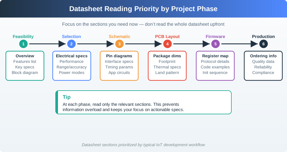
Figure 8.1: A reference value is useful only when the project phase and decision boundary are clear.
Use each reference item as a starting point for a short check: what unit is used, what condition makes it true, what assumption your project is making, and what source would settle an exact requirement. A protocol table can narrow choices, but the final design may need the IEEE 802.15.4 specification, IETF RFC, LoRa Alliance documentation, ESP32 datasheet, sensor datasheet, or vendor errata.
The figure shows the habit to use throughout this appendix. During feasibility, overview claims and key specifications may be enough to reject an unsuitable part. During component selection, electrical limits, range, accuracy, and power modes matter. During schematic, PCB, firmware, and production work, the same part needs pin diagrams, timing limits, package dimensions, register maps, initialization sequences, ordering codes, and reliability notes. A table row is therefore not a permanent truth; it is a cue to ask which decision is being made now.
Keep that boundary explicit when you use the protocol, sensor, ESP32, unit-conversion, and formula sections below. A BLE range row may support a first shortlist, but it cannot replace an on-site RSSI check. A BME280 current value may start a battery estimate, but it must be combined with sampling interval, regulator quiescent current, radio transmit current, and sleep leakage. A formula result should keep its units, assumptions, and rounding visible so another teammate can repeat it.
Boundary
Use It For
Lookup
Recall, comparison, and first-pass estimates.
Design
Full chapter, datasheet, standard, or bench measurement review when the value controls cost, safety, power, range, or compatibility.
Project
Unit, tolerance, operating condition, and failure consequence record before a value is reused.
8.7.1 Convert a Table Entry Into a Checkable Assumption
For project work, write the reference fact as an assumption that another teammate could verify. “BLE range is 10-100 m” is too broad. “This indoor beacon prototype assumes BLE advertisement packets remain readable at 8 m through one drywall wall, measured with RSSI above the app threshold on the chosen phone” is checkable. The reference table suggested the technology; the project assumption names the environment, device, metric, and test.
The same pattern applies across the appendix. ESP32 GPIO 34-39 are input-only, so a wiring plan should mark them as sensor inputs rather than relay outputs. A BME280 current value belongs in a duty-cycle calculation with sensor warm-up and sleep current. MQTT QoS 1 belongs with idempotent command handling because duplicates can occur. A link-budget formula belongs with antenna gain, receiver sensitivity, path loss model, installation height, and measured RSSI/SNR.
Use a compact assumption record before the value enters the capstone report: fact, source, unit or valid range, dependency, next check, owner, and review date. For an ESP32 pin choice, that record may say GPIO 34 is input-only and therefore can read an analog sensor but cannot drive a relay; GPIO 0, 2, 12, and 15 need boot-strap review before external circuits pull them. For an SHT31, DS18B20, or PMS5003 selection, it may record accuracy, interface, warm-up, airflow, enclosure, and replacement risk. For an SX1276 or RFM95 LoRa design, it may record regional channel plan, antenna gain, spreading factor, duty-cycle limit, RSSI/SNR target, and the field test that will validate the link budget.
The point is not to slow down every lookup. The point is to stop unreviewed reference facts from becoming hidden design commitments. A quick table value can be copied into the notebook in seconds, but the project should mark whether it is a rough estimate, a datasheet limit, a standard requirement, a library default, or a measured result from the actual build.
Copy the exact fact. Include the unit, row label, and section that supplied it.
Name the dependency. Explain which hardware, firmware, protocol, power, or user requirement depends on it.
Name the next check. Use a datasheet lookup, bench test, packet capture, calculator, or field measurement before treating the assumption as stable.
8.7.2 Reference Tables Compress Many Conditions
Compact tables hide the conditions that make a value true. Wireless range depends on frequency, transmit power, antenna gain, receiver sensitivity, path loss, walls, interference, installation height, and duty-cycle limits. Sensor accuracy depends on calibration, temperature range, supply voltage, self-heating, drift, sampling interval, and mounting. Current draw depends on active state, sleep state, radio burst length, regulator quiescent current, and firmware timing.
Standards links and datasheets matter because they define exact behavior. MQTT QoS uses packet exchanges such as PUBLISH, PUBACK, PUBREC, PUBREL, and PUBCOMP. CoAP confirmable messages use ACK and retransmission timers over UDP. I2C depends on pull-up resistors, bus capacitance, address conflicts, and clock speed. ESP32 boot pins can affect startup if external circuitry pulls them to the wrong state.
Every compressed value also has a revision problem. Vendor breakout boards may differ from the underlying chip datasheet because of regulator choice, level shifting, pull-up values, address jumpers, or board-layout limits. Library defaults may differ from a protocol specification because a driver chooses a timeout, retry count, payload size, keep-alive interval, or power mode. Regional rules may change what looks like a simple wireless comparison: LoRaWAN channel plans, transmit power, dwell time, and duty-cycle behavior are not the same in every region.
For that reason, a final capstone evidence packet should cite the exact reference revision and the observed project value when a number matters. Good records distinguish IEEE or IETF normative behavior from a vendor application note, a forum example, a library default, and a measurement from the team’s device. They also preserve the packet trace, oscilloscope capture, current profile, field RSSI/SNR reading, or calculator inputs that made the reference fact safe to reuse. That separation lets a future maintainer update one layer without guessing which assumptions were inherited from a table.
State
What Must Stay Visible
Specification
Protocol fields, timing, electrical limits, operating ranges, and conformance language.
The measured value, observed packet trace, or repeatable calculation that confirms the reference fact in the project context.
8.7.3 Try It: Check One Reference Fact
Before copying a value from a table into a capstone design, write one quick reference check:
Fact reused: the exact protocol limit, sensor range, formula, pin assignment, or conversion you plan to use.
Source location: the appendix section and, when exact behavior matters, the external standard or data sheet you will verify against.
Units and boundary: the unit, valid range, rounding rule, and any condition that changes the value.
Project assumption: the way your project depends on the value, such as battery sizing, enclosure choice, alert threshold, or network capacity.
Acceptance test: the bench test, calculation, or review step that proves the value is safe to use in your design.
Accept the reference only when the units, boundary conditions, and project dependency are explicit enough for another team member to repeat the check.
8.8 Key Concepts
Reference architecture: A validated system design template that documents components, data flows, and technology choices for an IoT deployment pattern.
Bill of materials (BOM): A structured list of hardware components, quantities, and costs used for procurement planning and project budgeting.
Protocol comparison matrix: A side-by-side comparison of communication protocols across range, data rate, power, topology, and typical use cases.
Worked example: A solved problem that shows inputs, method, intermediate steps, and final answer so the reasoning is visible.
Quick reference card: A compact summary of commonly needed facts such as pin assignments, units, ranges, and formulas.
Standards reference: A pointer to IEEE, IETF, alliance, or vendor documents that should be checked for exact protocol requirements.
Index: An organized cross-reference that maps terms to the chapters and sections where they are introduced and applied.
8.9 For Beginners: Appendix
An appendix is like a reference guide at the back of a textbook. You do not need to read it cover-to-cover. Use it when you need to remember a term, formula, sensor interface, pin assignment, or standards document while working on a project.
8.10 A. Glossary of IoT Terms
Term
Definition
6LoWPAN
IPv6 over Low-Power Wireless Personal Area Networks - Adaptation layer enabling IPv6 on IEEE 802.15.4 networks
ADC
Analog-to-Digital Converter - Hardware that converts continuous analog signals to discrete digital values
html`<div style="background: var(--bs-light, #f8f9fa); padding: 1rem; border-radius: 8px; border-left: 4px solid #16A085; margin-top: 0.5rem;"><p><strong>Average Current:</strong> ${battery_calc.avg_current.toFixed(3)} mA</p><p><strong>Battery Life:</strong> ${battery_calc.life_hours.toFixed(1)} hours (${battery_calc.life_days.toFixed(1)} days)</p>${battery_calc.life_years>=1?`<p><strong>Or:</strong> ${battery_calc.life_years.toFixed(2)} years</p>`:''}<p style="margin-top:0.5rem; font-size:0.9em; color:#666;">Example: A 2000mAh battery powering a device that draws 50mA when active and 0.05mA when sleeping, with 1% duty cycle (99% sleep time), will last approximately ${battery_calc.life_days.toFixed(0)} days.</p></div>`
8.16 G. References and Further Reading
MVU: IoT Standards Landscape
Core Concept: IoT standards come from different organizations - IEEE for physical/MAC layers (802.11, 802.15.4), IETF for internet protocols (CoAP, 6LoWPAN, RPL), and industry alliances for application-specific specs (LoRaWAN, Zigbee, Matter).
Why It Matters: Knowing which organization owns a standard tells you where to find official documentation, certification requirements, and future roadmaps for the technology you are using.
Key Takeaway: When researching a protocol, start with the standards body that owns it - IEEE for wireless PHY/MAC, IETF for IP-based protocols, and alliance websites for ecosystem-specific features.
Connectivity Standards Alliance (CSA): csa-iot.org - Zigbee and Matter standards
Bluetooth SIG: bluetooth.com - Bluetooth specifications
8.16.2 Key RFCs and Standards
Document
Title
RFC 7252
CoAP - Constrained Application Protocol
RFC 6550
RPL - Routing Protocol for LLNs
RFC 4944
IPv6 over 802.15.4 (6LoWPAN)
RFC 6282
6LoWPAN Header Compression
IEEE 802.15.4
Low-Rate Wireless PANs
IEEE 802.11
Wireless LAN (Wi-Fi)
8.17 Visual Reference Gallery
IoT Protocol Ecosystem
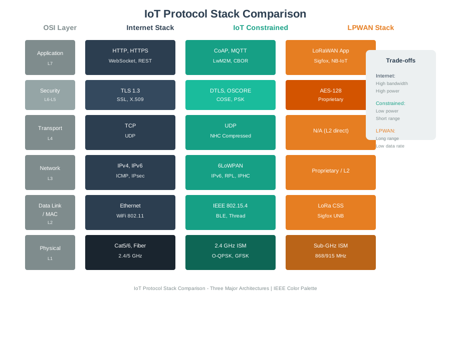
IoT Protocol Stack
The IoT protocol ecosystem spans multiple layers, each with specialized protocols optimized for constrained devices and networks.
ESP32 Architecture Overview
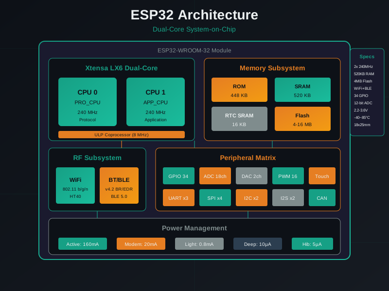
ESP32 Architecture
The ESP32 combines dual-core processing with integrated wireless connectivity, making it a popular choice for IoT prototyping and production.
Worked Example: Using the Appendix to Resolve a Missing I2C Device
Scenario: Your capstone project has a BME280 temperature, humidity, and pressure sensor plus a BH1750 light sensor, both using I2C. After wiring, only one sensor responds. You consult the appendix before rewriting code.
Appendix lookup (Section C: Common Sensor Specifications): - BME280: I2C address 0x76 or 0x77 (configurable via SDO pin) - BH1750: I2C address 0x23 or 0x5C (configurable via ADDR pin)
Problem identified: The possible addresses are different, so an address conflict is unlikely. The next check is wiring and bus assignment.
I2C debug:
$ i2cdetect -y 10 1 2 3 4 5 6 7 8 9 a b c d e f00:--------------------------70:------------ 76 --
Only one device (0x76) appears. BH1750 missing.
Solution: Check Section D (ESP32 Pin Reference): - Default I2C: SDA=GPIO 21, SCL=GPIO 22 - Verify wiring: BH1750 SDA connected to GPIO 19, which is SPI MISO rather than the default I2C SDA pin.
Fix: Move BH1750 SDA to GPIO 21. Both sensors now work.
Key insight: The appendix helped separate an addressing theory from a wiring fault. Quick lookups save time during prototyping when they are used with a clear diagnostic sequence.
Decision Framework: When to Use Appendix vs. Detailed Chapters
Situation
Best First Stop
Why
“What is the I2C address of BME280?”
Appendix
Quick lookup for a specific hardware fact
“How do I implement MQTT reconnection?”
Detailed chapter
Requires an algorithm, state handling, and error strategy
“What is the formula for link budget?”
Appendix
Quick formula reference
“Should I use CoAP or MQTT?”
Detailed chapter
Requires decision guidance and project context
“What is the MTU for 6LoWPAN?”
Appendix
Quick protocol specification lookup
Appendix strengths:
Pin assignments during wiring
Unit conversions during calculations
Protocol quick comparison
Formula lookups
Appendix limitations:
No design guidance (go to chapters)
No tutorials (go to chapters)
No troubleshooting (go to chapters)
Key insight: Use the appendix as a quick reference during hands-on work. Return to chapters for understanding why and how things work.
Common Mistake: Using Appendix as Primary Learning Resource
The mistake: A learner tries to learn IoT exclusively from the appendix, using the glossary, pin references, and formulas without reading the detailed chapters. The result is memorized definitions without enough context for design decisions.
Why It Happens: Appendix is concise and feels efficient. “I can learn IoT in 20 pages!”
Example of insufficient understanding:
Appendix: “MQTT is publish/subscribe, CoAP is request/response”
Missing context: When to use each? QoS implications? Power consumption differences?
Result: Chooses MQTT for battery device because “it’s popular” (wrong - CoAP would be better)
The Fix: Use the appendix for recall, not learning:
Read the detailed chapter (e.g., MQTT fundamentals)
Practice with examples
Use appendix as quick reference during design/coding
Return to chapter when deeper understanding is needed
Key insight: The appendix is a map, not a guidebook. It helps you navigate once you know the terrain; it does not teach the underlying engineering by itself.
Match the Protocol to Its Layer
Order the IoT Data Path
Common Pitfalls
1. Treating the appendix as primary learning material
The appendix is reference material, not a structured learning path. Reading it linearly without the conceptual grounding from main chapters produces memorization without understanding. Use appendix sections as deep-dives after the relevant main chapter concepts are understood, not as standalone introductions.
2. Not cross-referencing appendix material with main chapters
Appendix content is only valuable when connected to the problems it solves. When using a formula from the appendix, trace it back to the chapter where it was applied in context. The mathematical derivation alone without the application context rarely produces actionable understanding.
3. Copying appendix code examples without adapting to your hardware
Code examples in reference appendices are illustrative, not deployment-ready. They typically use placeholder device IDs, hardcoded credentials, and simplified error handling. Always adapt examples to your specific hardware, add proper error handling, and validate against your target environment before relying on them in production.
Label the Diagram
Code Challenge
8.18 Summary
This appendix serves as a quick reference companion to the main textbook:
Glossary: 45+ IoT terms with concise definitions
Protocol Comparisons: Side-by-side tables for wireless, LPWAN, and application protocols
Sensor Specifications: Common temperature, motion, and distance sensors with specs
ESP32 Pin Reference: GPIO capabilities and common pin assignments
Engineering Formulas: Essential calculations for link budgets, battery life, and electronics
8.19 Knowledge Check
Auto-Gradable Quick Check
Concept Relationships
Appendix serves as the connective tissue between modules: Each table, formula, or pin reference draws from concepts explained in detail elsewhere: 6LoWPAN in networking, MQTT in application protocols, BME280 specifications in sensors, and ESP32 GPIO in prototyping. The appendix does not introduce new concepts; it consolidates them for quick reference.
Standards organizations map to technology layers: IEEE owns physical/MAC layers such as 802.11 and 802.15.4, IETF owns IP-based protocols such as CoAP, 6LoWPAN, and RPL, and industry alliances such as the LoRa Alliance and CSA own ecosystem specifications. Understanding this mapping helps you find authoritative documentation.
Protocol comparison tables reveal design trade-offs: The short-range table shows the relationship between data rate and power, such as Wi-Fi being higher rate and higher power while Zigbee is lower rate and lower power. The LPWAN table shows licensed vs. unlicensed spectrum trade-offs, such as NB-IoT using licensed spectrum and LoRaWAN using unlicensed spectrum. These tables do not make design decisions for you; they help you ask the right questions before consulting detailed chapters.
Formulas connect hardware to behavior: Link budget calculations tie transmit power to receiver sensitivity through path loss. Battery-life calculations connect current consumption to duty cycle. The appendix does not teach when to apply these formulas; it assumes you have already learned the underlying principles.
Pin reference prevents hardware mistakes: ESP32 GPIO tables show which pins have ADC, DAC, and touch capabilities, default I2C/SPI assignments, and boot-mode restrictions. This reference does not teach you how I2C works; it helps you avoid wiring mistakes after you have learned the protocol.