Trace an I²C address and missing acknowledge
Distinguish I2C addressing and diagnose a missing ACK by matching scanner results to SDA on the ninth SCL pulse.

Use the I2C Protocol route to diagnose a missing ACK: identify the 7-bit address, inspect the write address byte, and check the ninth clock before changing sensor code.
Predict the reading, then compare it with the measurement.
Wokwi ESP32
Third party ToolDistinguish I2C addressing and diagnose a missing ACK by matching scanner results to SDA on the ninth SCL pulse.
Open the ESP32 editor, paste diagram.json, then paste sketch.ino.
Open Wokwi to paste in the files (new tab)Get the files
Use both prepared files. This is a paste-in setup; saving a project requires a Wokwi account.
sketch.ino
- Use the launch button above to open the ESP32 editor in Wokwi.
- Select the editor’s diagram.json tab and replace all its text with the supplied diagram.json.
- Select the sketch.ino tab, replace all its text with the supplied sketch.ino, then click Start Simulation.
Steps
Step 1
- Do
- In the Wokwi editor, read the chapter's inline I2C scanner exercise, then paste this diagram and sketch and inspect the MPU6050 and analyzer wiring.
- You will see
- Input: loaded one MPU6050, one ESP32, and a two-channel logic analyzer in the public Wokwi editor. Observed: SDA goes to GPIO21 and analyzer D1; SCL goes to GPIO22 and analyzer D0. Observed: the committed starting diagram connects MPU6050 AD0 to ground. Observed: the stopped Simulation panel showed no analyzer samples yet.
- Why it matters
- The chapter's inline scanner explains the basic bus probe. This separate lab adds analyzer evidence for address and acknowledge behavior. Grounding AD0 selects the first simulated address. The stopped editor is a wiring baseline, not proof of an ACK.
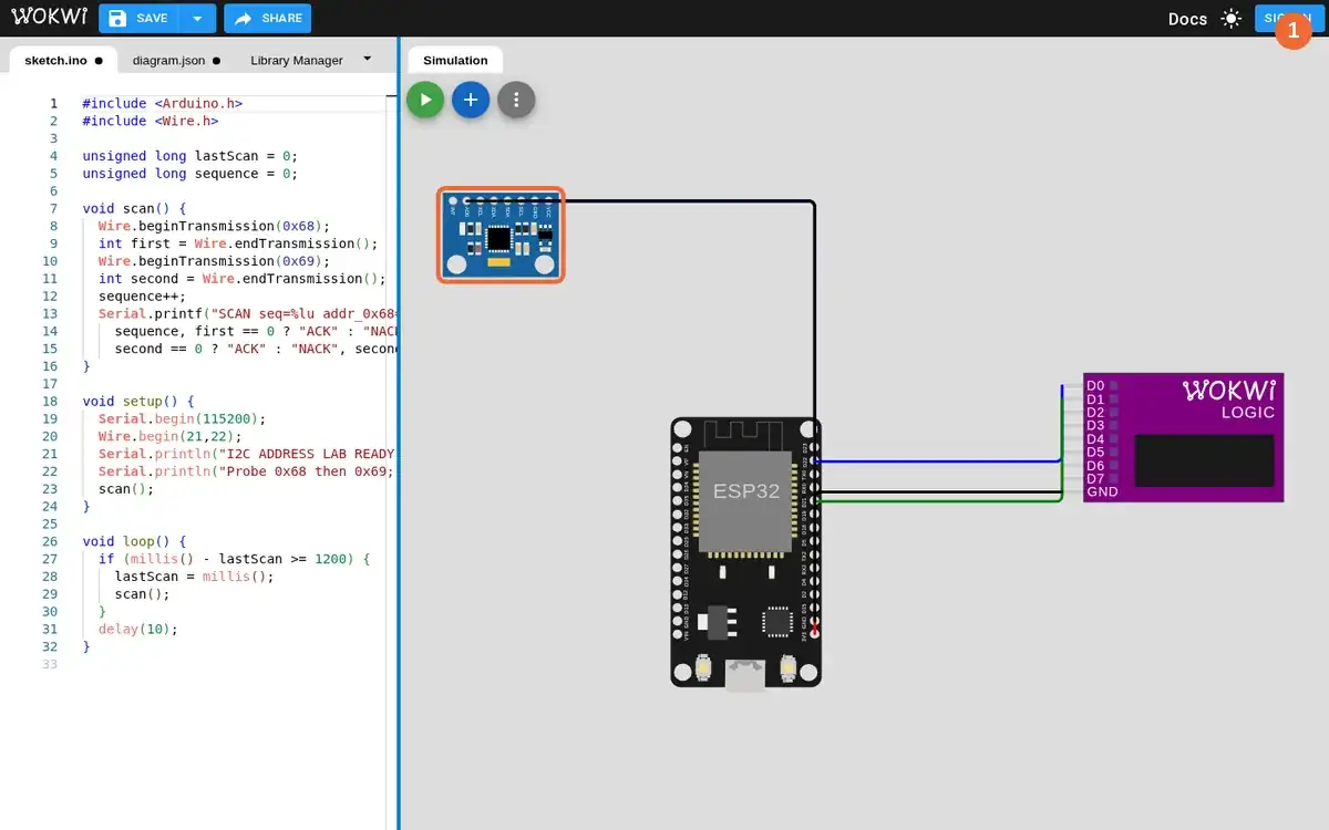
Step 1 · Wokwi ESP32; numbered callout added to a real capture. Enlarge screenshot (new tab) Step 2
- Do
- In the Simulation panel, start Wokwi and read the first address scan in Serial Monitor.
- You will see
- Input: started the committed AD0-to-ground circuit. Observed: `SCAN seq=1 addr_0x68=ACK(0) addr_0x69=NACK(2) t_ms=533`. Observed: later `SCAN seq=2 addr_0x68=ACK(0) addr_0x69=NACK(2) t_ms=1203`. Observed: the logic analyzer sample counter advanced while the scan ran.
- Why it matters
- The same sensor responds at 0x68 in this wiring state. Wire status 0 reports an acknowledged address. Wire status 2 reports an unacknowledged address. Repeating the scan separates a stable configured address from a one-off boot message.
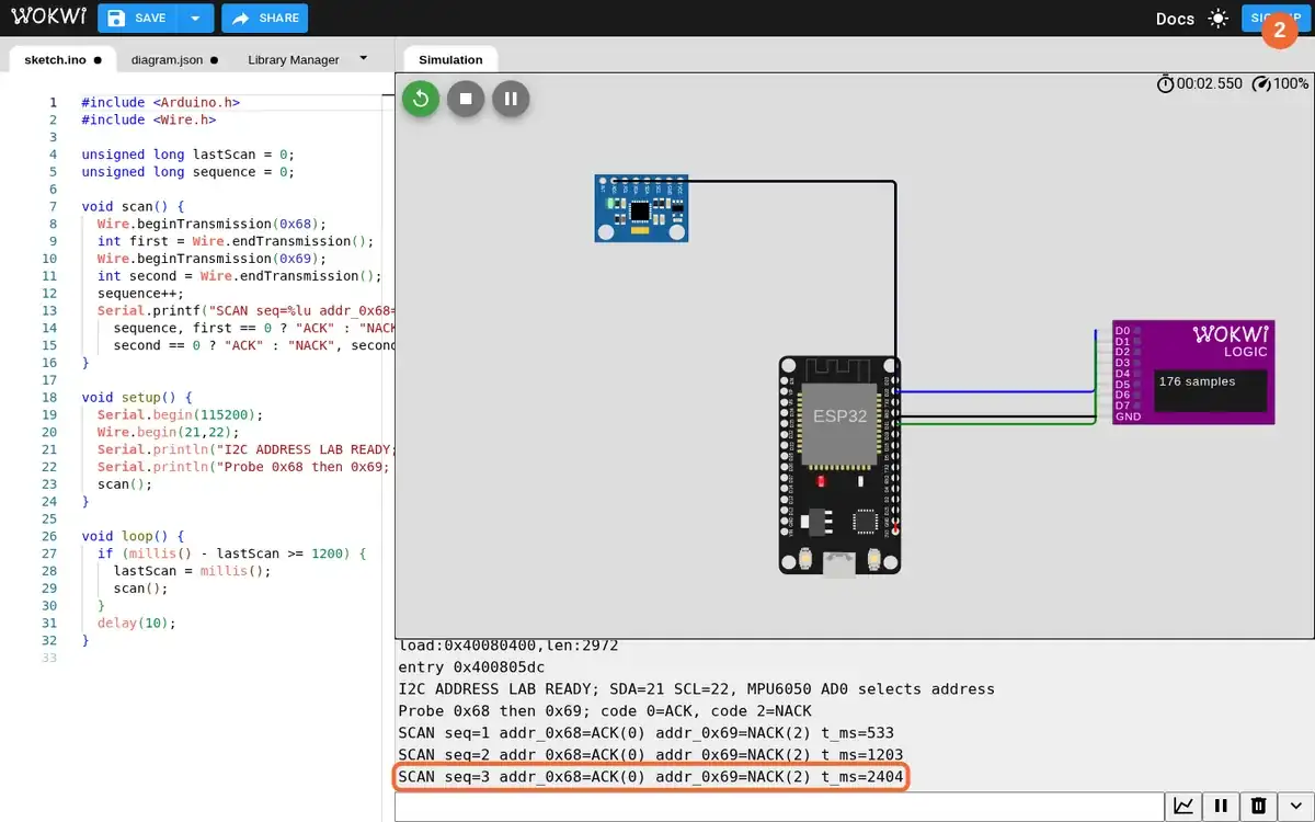
Step 2 · Wokwi ESP32; numbered callout added to a real capture. Enlarge screenshot (new tab) Step 3
- Do
- In the Wokwi Simulation panel, watch the logic analyzer sample counter and inspect the exported SCL/SDA frame for the grounded AD0 state.
- You will see
- Input: left AD0 grounded while another scan completed. Observed: the analyzer showed 234 captured samples in the running editor. Observed VCD at 532.825 ms: address byte 0xD0 had ninth-clock SDA LOW, an ACK. Observed VCD at 533.091 ms: address byte 0xD2 had ninth-clock SDA HIGH, a NACK.
- Why it matters
- 0xD0 and 0xD2 are the write address bytes for 7-bit addresses 0x68 and 0x69. SDA LOW on the ninth clock is an acknowledge from the selected device. SDA HIGH on that clock leaves the unconfigured address unacknowledged. The VCD was recorded by the real Wokwi analyzer, not drawn from the serial text.
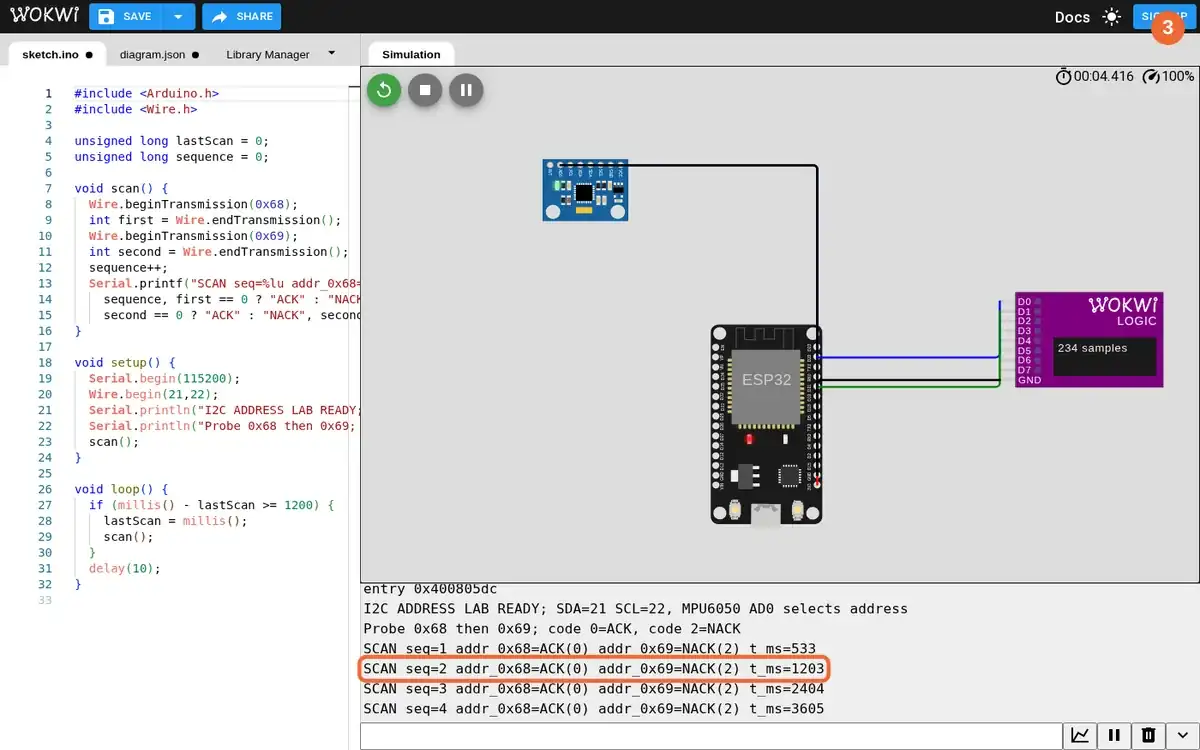
Step 3 · Wokwi ESP32; numbered callout added to a real capture. Enlarge screenshot (new tab) Step 4
- Do
- In Wokwi's diagram.json editor, stop simulation, change only MPU6050 AD0 from GND to 3V3, then start the same scanner sketch again.
- You will see
- Input: changed the real editor connection from `sensor:AD0` to ESP32 ground into `sensor:AD0` to ESP32 3V3. Observed: the sketch rebuilt and ran with the changed diagram. Observed: `SCAN seq=1 addr_0x68=NACK(2) addr_0x69=ACK(0) t_ms=533`. Observed: the 0x68 and 0x69 results reversed without a scanner-code change.
- Why it matters
- The modified Wokwi device address follows AD0 high. The old address now lacks a responding device. The new address gets the sensor's acknowledge. Holding the sketch constant makes wiring the controlled variable.
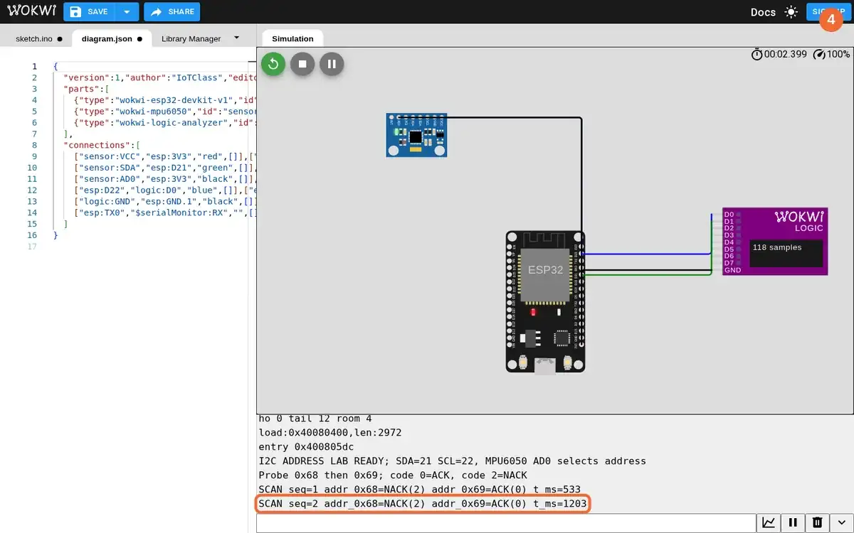
Step 4 · Wokwi ESP32; numbered callout added to a real capture. Enlarge screenshot (new tab) Step 5
- Do
- In the Wokwi Serial Monitor and the exported analyzer view, compare both address frames after AD0 is high.
- You will see
- Input: left AD0 connected to 3V3 for a second scan. Observed: `SCAN seq=2 addr_0x68=NACK(2) addr_0x69=ACK(0) t_ms=1203`. Observed VCD at 532.825 ms: 0xD0 had ninth-clock SDA HIGH, a NACK. Observed VCD at 533.080 ms: 0xD2 had ninth-clock SDA LOW, an ACK.
- Why it matters
- The address bytes remained the same across the two runs. Only which address received an acknowledge changed. The ninth clock in the analyzer agrees with the scanner's Wire status. The distinction is bus response, not a renamed serial label.
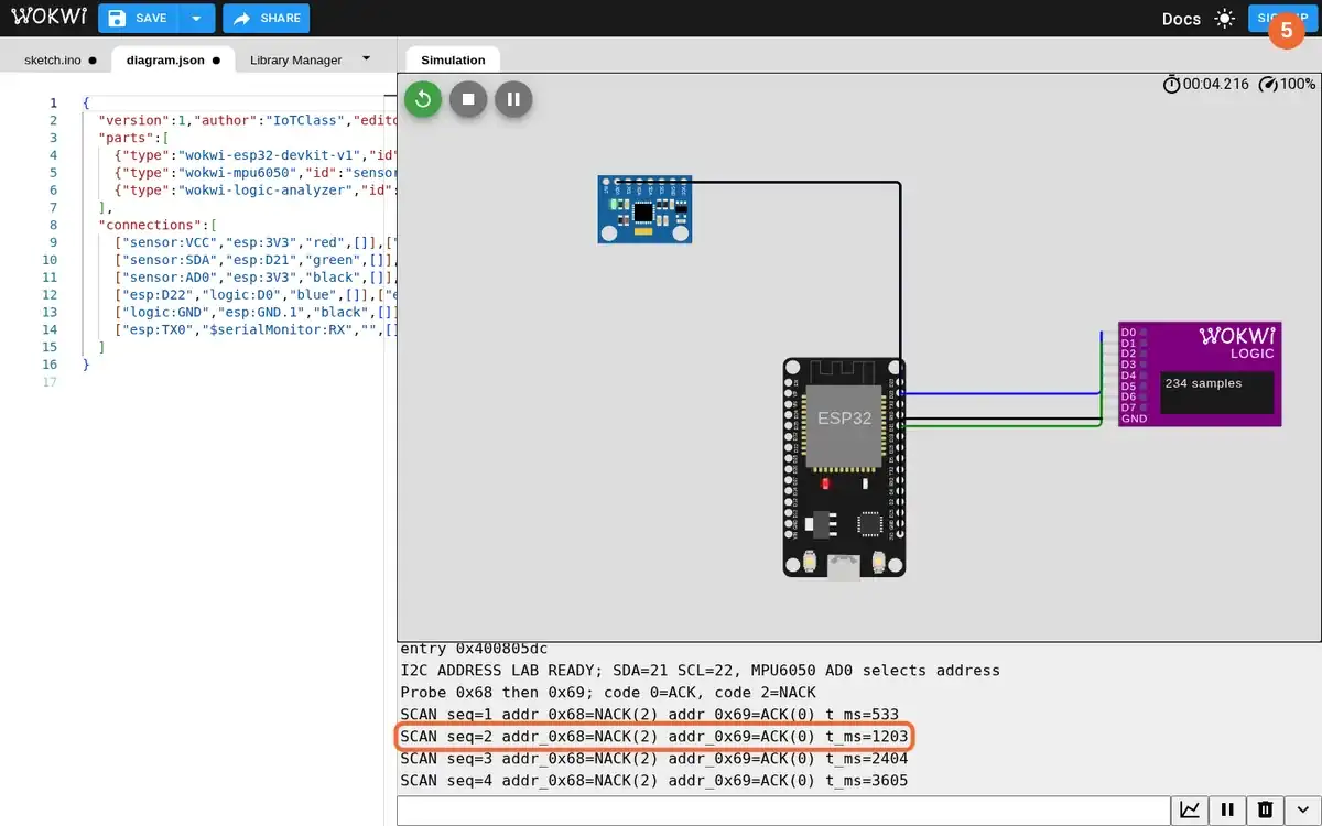
Step 5 · Wokwi ESP32; numbered callout added to a real capture. Enlarge screenshot (new tab) Step 6
- Do
- In the Wokwi Simulation panel, capture the final circuit, analyzer count, and repeated scan line, then stop to export the second VCD.
- You will see
- Input: continued the AD0-high run and stopped the real simulator after the capture. Observed: `SCAN seq=3 addr_0x68=NACK(2) addr_0x69=ACK(0) t_ms=2404`. Observed: the analyzer sample counter reached 350 in the running screenshot. Observed: Wokwi downloaded both AD0-ground and AD0-high VCD files for the comparison.
- Why it matters
- The repeated scan confirms the selected address in the high state. The analyzer proves SCL and SDA activity while the ESP32 scans. The saved VCDs preserve the ninth-clock evidence for both address configurations. This simulated bus run does not establish electrical rise time or physical wiring quality.
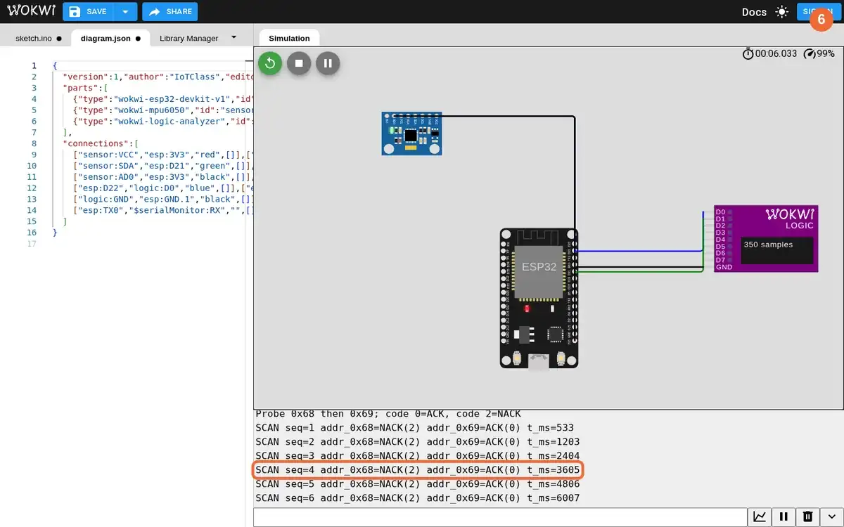
Step 6 · Wokwi ESP32; numbered callout added to a real capture. Enlarge screenshot (new tab)
Chapter checks
These questions refer to the chapter’s examples. Use the return links to review their answers.
Two sensors work separately but fail when connected together with the same I2C address; what should be checked first?
Return to the chapter’s knowledge checkWhy does a shared I2C bus need pull-up resistors on SDA and SCL?
Return to the chapter’s knowledge check