← Back to the chapter · Previous detail
Technical detail · Hardware Prototyping Case Studies
Review electrical proof before PCB release
Inspect Figure 14.7 and ask which missing record should stop a prototype from advancing to PCB layout.
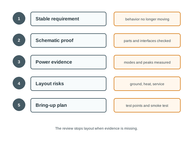
In Figure 14.7, the ESP32’s 3.3 V rail falls to 2.6 V during the approximately 300–500 mA Wi-Fi transmit surge. The trace crosses the dashed threshold at approximately 2.7 V, and reset coincides with the dip. The red FAIL result marks failed electrical proof: the rail falls about 0.1 V below the trip point. The lower panel lists four PCB-release checks: stable behavior, stable interfaces, electrical proof, and a bring-up plan. This failed rail test alone stops layout release. Revise the power path and repeat the measurement; release still requires mature evidence across all four checks.
PCB readiness evidence:
Stable behavior. The required sensing, actuation, communication, sleep, reset, and safe-output behavior are proven.
Stable interfaces. Pin map, bus addresses, connector plan, voltage levels, placement, and service access are not still changing.
Electrical proof. Power modes, peak loads, reset behavior, timing signals, and noise-sensitive readings are measured.
Bring-up plan. The first board has test points, programming access, inspection steps, smoke tests, and rollback steps.
Decision: If those records are missing, the next revision should be an integration prototype or schematic review, not layout release.