NB-IoT Modem Bring-Up
NB-IoT Modem Bring-Up
Lab Bench Setup
Start with a bench that can expose faults early. A reliable NB-IoT lab is more than a USB cable and a terminal window.
Step 1: Record the physical bench boundary on your own hardware
- At the bench, label the board supply, modem rail, UART voltage, antenna port, SIM profile, and whole-board current measurement point.
- In the terminal, capture boot time and firmware identity before issuing network commands; a stable
ATreply alone does not prove current margin. - Confirm that supply voltage stays within the module’s limits during a burst and that the UART logic level matches the board.
- Save the antenna and enclosure arrangement so later field readings can be compared with the same RF path.
- No physical NB-IoT board or instrument was attached here; these checks require your own hardware and are not implied by the local dry run.
Use a supply that can tolerate modem current bursts, plus a measurement point for whole-board current. Do not infer battery life from modem-only current.
Use the correct logic voltage, a stable baud rate, and a way to capture timestamped terminal logs.
Record SIM or eSIM identity, subscription status, intended operator profile, roaming policy, and any private APN requirement.
Use the correct antenna for the deployment bands and avoid testing in a location where coverage is unknown but not being measured.
Prepare a minimal endpoint that records payload time, device identity, transport path, and application-layer acknowledgement.
Bring-Up Workflow
Step 2: Complete the six bring-up gates in order on your own hardware
- In the terminal, log the Power safely and Prove modem access gates with supply readings, boot time,
ATresponse, and firmware identity. - Add Prove subscription and Prove network records with SIM readiness, registration, cell, signal, and attach time.
- For Prove application, send a payload ID and find the same ID in the endpoint receipt rather than accepting a socket
OKalone. - For Prove recovery, interrupt the modem and record whether the host reconnects and sends queued work once.
- The six gates below are the checklist; no modem, subscription, endpoint, or electrical measurement was run for this example.
Generic AT Checkpoints
Use short command checkpoints and record the response. Avoid turning the lab into a copy-paste script that hides judgment.
Step 4: Query each AT checkpoint on your own modem
- In the terminal, send
ATrepeatedly after boot and save its timestamped response; an intermittent reply points back to power, UART, or reset behavior. - Send
AT+CPIN?and record SIM readiness or the exact provisioning failure before attempting attach. - Send
AT+CEREG?,AT+CSQ, and your vendor’s cell-statistics command; pair the registration state with cell and signal context. - Read
AT+CGDCONT?and compare the APN or profile with the subscription requirement before a data send. - These are generic checkpoints from the chapter, not a claimed transcript. No modem AT commands were issued for this example; use your module’s command manual for syntax and timeouts.
AT
Expected evidence: the modem returns a valid response repeatedly after power-up and does not reset under load.
AT+CPIN?
Expected evidence: the identity is ready for registration, or the lab records the exact provisioning problem.
AT+CEREG?
Expected evidence: the device reaches an acceptable EPS registration state and the log includes the time needed to get there.
AT+CSQ plus vendor-specific radio statistics
Expected evidence: the lab records enough signal and cell information to explain retries, coverage class, and attach delay.
AT+CGDCONT?
Expected evidence: the APN or data profile matches the operator, private-network, or platform requirement for the pilot.
Connection and data commands can take far longer than simple status commands, especially in weak coverage. Your firmware should use command-specific timeouts and state-machine logging, not one universal timeout.
Data Path Validation
The first payload test should be deliberately small. Inspect Figure 1 to see which six records must describe the same transaction; the goal is to prove the path and logging, not to stress throughput.
Step 5: Match one payload across the path on your own hardware
- In the modem terminal, send a short payload with a unique ID and log the request, response, timestamp, and registration state.
- In the cloud endpoint, find the same ID and server timestamp; a modem
OKwithout this receipt is incomplete. - Mark boot, registration, send, active window, and sleep on the whole-board current trace for that transaction.
- Record the requested and granted power timers beside the trace, then check whether a retry would duplicate the application side effect.
- This example did not send a cellular payload or receive a cloud acknowledgement; the local UDP CoAP test elsewhere in this lab set is separate evidence.
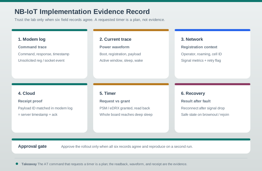
Read Figure 1 from the modem command trace and current waveform to registration context and cloud receipt proof. Then compare requested timers with the values the network actually granted and finish with the recovery result. A payload ID and timestamps tie these records together. This evidence packet connects bring-up to approval: a successful command without server receipt, measured energy, grant readback, or reproducible recovery remains an incomplete result.
Command trace
Save the command, response, timestamp, and any unsolicited registration or socket event.
Current waveform
Mark boot, registration, payload send, active window, sleep entry, wake, and recovery on the current trace.
Registration context
Record operator profile, roaming state, cell identity, signal metrics, and any coverage-enhancement or retry indicator available.
Receipt proof
Match the payload ID in the modem log to a server-side timestamp and acknowledgement.
Power-Mode Verification
Power-mode implementation has two separate questions:
Step 6: Compare the browser power model with granted timers
- In the NB-IoT Power Saving Mode Animation below, choose Water meter and press Step. This browser workbench was run here.
- Its displayed model read
Reachable for 2 min/day,0.85 mAh/day, andEvidence: verify granted values; none is a measured network grant or current waveform. - On your own modem, request PSM or eDRX and save both the request and the granted timer readback from its documented command or URC.
- Compare the actual whole-board current waveform with the active, paging, and sleep windows, including host and regulator current.
- Test a downlink attempt during sleep, record the delivery delay, and reject the mode if it misses the product’s reachability target.
Run it: Before filling the request-versus-grant rows below, drive the power-timeline animation. Load a preset such as Water meter, choose Power strategy PSM after active timer, and set the T3324 active time, eDRX cycle, and Report interval you intend to request. Press Play and read the 24-Hour Reachability Timeline and Current Draw Model to see whether the whole board returns to the deep-sleep current, then switch Power strategy to eDRX reachable sleep and set a Downlink attempt to test the reachability window. Record what the device requested, what the timeline treats as granted behavior, whether the whole cycle reaches low power, and whether the reachability window is tolerable.
Record the requested PSM or eDRX configuration, the firmware version, and why the application needs that reachability behavior.
Read back the granted behavior and confirm it appears in both the modem log and current trace.
Confirm the MCU, sensors, level shifters, regulators, and modem all enter the intended low-power state.
If the cloud needs quick downlink, validate that the active window or eDRX paging behavior is sufficient.
The command that requests PSM or eDRX is not deployment evidence. Approval needs readback, network grant, current waveform, and an application test showing the device wakes and communicates as expected.
Recovery Tests
Recovery is where many prototypes fail. Add these tests before a field pilot:
Step 7: Fault the recovery path on your own hardware
- Queue a payload with a unique ID, reset the modem, and log whether the host detects loss and reinitializes it.
- Repeat with controlled coverage loss and a blocked cloud endpoint; record backoff, retry ceiling, and whole-board current during failure.
- On recovery, compare the delivered payload ID with the queue record and prove that duplicate processing is suppressed.
- Repeat near the board’s specified minimum voltage and watch for attach loops that keep the device awake.
- No reset, attenuation, cloud outage, or battery test was performed here; the four fault cards below define the on-hardware observations.
Modem reset
Reset the modem while the host stays awake. Confirm the host detects loss, reinitializes the modem, and resends any queued payload once safe.
Coverage loss
Move to a known poor-coverage condition or controlled attenuation. Confirm retry limits, backoff, and battery protection.
Cloud unavailable
Block the endpoint or reject the application request. Confirm payload queueing, duplicate suppression, and observability.
Low-battery restart
Restart near the minimum operating voltage and confirm the firmware avoids attach loops that drain the remaining battery.
Field Pilot Gate
A bench pass is not field readiness. Before rollout, record a field gate that proves the selected module, antenna, enclosure, operator profile, and firmware policy work together at representative sites.
Step 8: Review the field pilot evidence on your own hardware
- At each representative site, attach the final enclosed board and record its antenna orientation, cell, signal, and registration time.
- Match one payload ID per site across modem log and cloud receipt, with retry and acknowledgement timestamps.
- Record the granted timers, whole-board sleep current, wake-and-send result, and recovery after a controlled reset.
- Use the gate table below to mark proceed, revise, or reject with the exact missing record and responsible owner.
- The worked gate is an example only; no site, enclosure, operator, or field pilot was tested for this example.
| Gate | Pass evidence | Reject or rework signal |
|---|---|---|
| Installation | Final enclosure, antenna orientation, and mounting notes match the pilot plan | A smartphone signal check is the only coverage evidence |
| Registration | Attach and registration logs succeed at normal and hard locations | The device succeeds on the bench but fails in the installed position |
| Application | Payload IDs match cloud receipt, acknowledgement, retry, and duplicate-suppression logs | Network attach works but the application path fails silently |
| Power recovery | Current trace shows return to the expected sleep state after normal, weak-coverage, and reset cases | Retry loops or maintenance windows leave the device awake |
| Rollout support | Firmware version, profile ID, operator ticket path, and next-action owner are recorded | Failures cannot be assigned to hardware, subscription, network, or cloud evidence |
Technical boundaries. The browser power model is not a measured network grant or current waveform. No modem, subscription, endpoint, electrical measurement, or field pilot was tested for this example.