22 Power Accuracy and Field Hardening
Self-Heating, Settling, and Adaptive Sampling
self-heating, sensor settling, power budget, adaptive sampling, ESP32 deep sleep, field hardening
22.1 Start With the Measurement Story
A field sensor has to be accurate after vibration, moisture, temperature swings, and low battery states. The design starts by naming the threats and deciding which protection, calibration, and evidence checks keep the reading usable.

Phoebe’s Why
This chapter’s own pitfall list warns that “battery voltage drops nonlinearly with state-of-charge and temperature” without saying why, and it is actually two separate effects stacked together. One is the instantaneous kind: internal resistance sags the terminal voltage under load, and it recovers as soon as the load is removed. The other is permanent: the cell’s open-circuit voltage itself droops as the chemistry depletes, chemistry-dependent in shape and not recoverable by resting. Either one matters on its own, but they matter together for this chapter’s self-heating story if the thermistor’s excitation current is drawn straight from the battery rail through a fixed resistor rather than a regulated current source: as the battery droops for either reason, the excitation current droops with it, and because self-heating error scales with current squared, a tired battery can silently swing a design from “over-heating fresh” toward “under-signal old” – without a single line of firmware changing.
The Derivation
Terminal voltage sags from the load-dependent internal-resistance term, on top of the chemistry’s own state-of-charge droop:
\[V_{term} = V_{oc}(\mathrm{SoC}) - I\,R_{int}\]
For excitation drawn through a fixed series resistor rather than a regulated current source, the sense current tracks the battery rail directly, so this chapter’s own self-heating relationship inherits that dependence:
\[I \propto V_{batt} \quad\Rightarrow\quad P = I^2R \propto V_{batt}^2 \quad\Rightarrow\quad \Delta T = \frac{P}{\delta} \propto V_{batt}^2\]
Worked Numbers: This Chapter’s Own Self-Heating Example
Reusing this chapter’s own dissipation constant \(\delta=2\) mW/°C and \(\Delta T_{fresh}=0.10\)°C at \(P=0.2\) mW, against a catalog-typical lithium-primary droop from \(3.6\) V fresh to a \(3.0\) V near-end-of-life rail:
- Excitation-current ratio: for a fixed series resistor, current scales with \(V_{batt}\), so the power ratio is \((3.0/3.6)^2=0.694\).
- Self-heating at end of life: \(\Delta T_{depleted}=0.10\times0.694=0.0694\)°C – smaller self-heating error than the fresh-battery case this chapter already worked out.
- The catch: the excitation signal itself shrank by the same \(3.0/3.6=83.3\%\), so the ADC counts carrying the reading lost proportional resolution exactly when the sensor also needed to work harder against a possibly colder, harsher field environment. A field log that only tracks self-heating error would show the reading getting more accurate near end of life while the actual signal-to-noise ratio was getting worse.
- Why this belongs beside the “assuming linear discharge” pitfall above: a regulated current source removes this coupling entirely, because \(I\) stops depending on \(V_{batt}\) – which is exactly the kind of design evidence this chapter’s field-hardening checklist should record, not assume.
22.2 Learning Objectives
After this page, you should be able to:
- Explain how self-heating and settling delay can make low-power readings inaccurate.
- Calculate when excitation current violates a temperature sensor’s self-heating error budget.
- Configure wake-source and adaptive-sampling patterns without hiding recovery costs.
- Build a field-hardening checklist for radio bursts, peripherals, wake latency, and battery behavior.
22.3 Why This Follows the Main Power Chapter
Low-Power Sensor Networks builds the normal wake-read-transmit-sleep cycle. This page tests the cycle against the failure modes that appear after deployment: the sensor warms itself, conversion timing changes the reading, firmware sleeps without a recovery path, or adaptive sampling saves energy while losing important events.
22.4 Saving Power Can Corrupt the Measurement
Low-power sensor nodes live by duty-cycling: sleep, wake, read, sleep again. But two power-related effects sit directly between “save energy” and “get a correct reading,” and both are easy to miss because the data still looks plausible.
The first is self-heating: the very current you push through a resistive sensor to read it dissipates power and warms the element, biasing a temperature reading upward. The second is warm-up and settling: a sensor that was just powered on after sleep has not yet stabilised, so an eager reading taken too soon is wrong. Both are trade-offs of energy against accuracy.
A practical power plan therefore starts with a measurement-quality budget, not just a battery-life target. For a thermistor node, for example, the designer chooses the excitation current, the on-time, the settling delay, and the radio schedule together. Reducing current may improve battery life but lower ADC signal-to-noise ratio; increasing current may clean up the code but heat the sensing element; shortening the delay may save milliseconds but sample a filter that is still moving.
The field symptom is subtle: the node seems reliable because it wakes on schedule and uploads data, yet its readings shift with sample rate, enclosure airflow, or firmware changes. When changing a power setting changes the measured value, the measurement chain is part of the power design. Treat each wake cycle as a small experiment: energise the sensor, wait for the documented condition, convert, verify the result is within range, transmit only when needed, and then sleep. If the number changes after only the sleep interval changes, investigate timing before recalibrating the sensor.
Intuition: a thermistor is a tiny heater as well as a thermometer. Read it gently and briefly and it reports the world; read it hard and continuously and it partly reports itself.
Overview Knowledge Check
22.5 Self-Heating Math and Excitation Budget
The temperature error from self-heating is the dissipated power divided by the sensor’s dissipation constant (a datasheet figure in milliwatts per degree):
Power dissipated:  P = I^2 × R
Self-heat error:   ΔT = P / δ
  δ = dissipation constant (mW per °C), from the datasheet
Worked example: why doubling the current is not free
Thermistor, dissipation constant δ = 2 mW/°C (still air).

Read with sense power P = 0.2 mW:
  ΔT = 0.2 / 2 = 0.10 °C error   (small, tolerable)

Push 2x the current for a bigger signal. Because
P = I^2 R, power rises 4x to 0.8 mW:
  ΔT = 0.8 / 2 = 0.40 °C error

Push 4x the current -> 16x power = 3.2 mW:
  ΔT = 3.2 / 2 = 1.6 °C error
Signal grows with current, but self-heating error grows with current squared. That is the crux of the trade-off: cranking up excitation to improve SNR quietly poisons accuracy far faster than it helps.
Use the equation as a gate before firmware is considered done. If the error budget allows only 0.25 °C of self-heating and the dissipation constant is 2 mW/°C, the excitation budget is 0.5 mW. A 10 kΩ thermistor at that limit can carry only about 0.22 mA, because I = sqrt(P/R) = sqrt(0.0005 W / 10000 Ω). A convenient 1 mA test current would dissipate 10 mW and create about 5 °C of self-heating in the same condition.
That arithmetic explains why production firmware often pulses a divider or sensor rail through a MOSFET, discards the first sample after wake, averages only inside a bounded measurement window, and stores the actual excitation time with the reading. The goal is not the lowest instantaneous current; it is a repeatable energy packet whose thermal error, ADC noise, and settling time are all known.
The low-power win: pulse the excitation. Power the sensor only during the brief moment of measurement, so the average dissipation — and thus the steady self-heat rise — stays tiny while the instantaneous signal is strong.
Practitioner Knowledge Check
22.6 Warm-Up, Airflow, Accuracy
Duty-cycling introduces its own errors on top of self-heating, and they interact in ways that shape the whole power budget.
Settling after wake
A freshly powered sensor and its filter network need time to stabilise. Electrically, a filtered node settles over several RC time constants; many sensors also quote a start-up or stabilisation time that must elapse before the reading is valid.
Thermal mass lags
A temperature sensor has physical mass, so it follows the environment with a lag. Sample too soon after a change, or too soon after wake, and you read where the world was, not where it is.
Airflow changes self-heating
The dissipation constant is smaller in still air than in moving air or liquid, so the same sense power causes a larger self-heat rise in still air. The identical sensor can read differently just because the breeze changed.
Settling dominates the energy bill
For slow sensors, the time spent waiting to settle can use more energy than the conversion itself. That creates real tension: wait longer for accuracy, or sleep sooner to save charge.
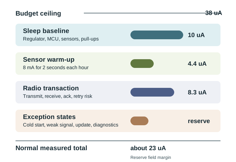
The ledger view also changes how failures are budgeted. A node that normally sleeps for 99% of the hour may still need a reserve for cold starts, low-battery retries, cloud outages, or a stuck sensor that forces extra reads. If the normal cycle already consumes the whole budget, exception paths drain the battery first and accuracy degrades next as firmware starts cutting settle time to recover.
The design that wins treats accuracy and energy as one coupled problem: pulse the excitation to limit self-heating, allow just enough settling time for the required accuracy, measure the radio burst separately from the sensor warm-up, and pick a sensor whose thermal and electrical time constants fit the duty cycle. Optimising energy while ignoring settling gives a node that lasts for years and reports numbers that were never quite right.
Under-the-Hood Knowledge Check
22.7 ESP32 Deep-Sleep Wake Sources
The ESP32 offers multiple wake sources for deep sleep mode (see also Common Power Pitfalls for what happens when you forget to configure one):
- Timer wake –
esp_sleep_enable_timer_wakeup(microseconds)– Most common for periodic sensing - GPIO wake (EXT0) – Wake on single RTC GPIO pin state change (e.g., button press, PIR sensor)
- GPIO wake (EXT1) – Wake when multiple RTC GPIOs match condition (AND/OR logic)
- Touchpad wake – Wake on capacitive touch sensor activity (ESP32 has 10 touch-capable pins)
- ULP coprocessor – Ultra-low-power coprocessor can monitor sensors and wake main CPU only when thresholds are exceeded
ESP32 power mode comparison:
| Mode | Current | What Stays On |
|---|---|---|
| Active (CPU + Wi-Fi) | 160-240 mA | Everything |
| Modem sleep | 20-40 mA | CPU active, Wi-Fi wakes at DTIM intervals |
| Light sleep | 0.8 mA typical | CPU paused, Wi-Fi suspended, RAM retained |
| Deep sleep | 10-150 uA | RTC controller + RTC memory only |
| Hibernation | 2.5-5 uA | RTC timer only (no RTC memory) |
22.8 Concept Check: Deep Sleep Wake Sources
22.9 Basic Deep Sleep
Goal: Make ESP32 read a sensor, send data, then sleep for 10 minutes.
Code structure:
#include <esp_sleep.h>

void setup() {
    // Read sensor
    float temp = readTemperature();

    // Send data (Wi-Fi or LoRa)
    sendDataToCloud(temp);

    // Configure wake timer
    esp_sleep_enable_timer_wakeup(10 * 60 * 1000000ULL); // 10 minutes in µs

    // Enter deep sleep
    esp_deep_sleep_start();
}
void loop() { /* Never runs */ }
Expected result: Current drops from 80mA active to 10µA sleep
22.10 Power-Aware Sensor Fusion
Goal: Combine GPS + accelerometer + barometer, but only wake GPS when movement detected.
Strategy:
- Accelerometer runs continuously (low power)
- GPS off unless accelerometer detects motion
- Barometer updates every minute
- Transmit fused data every 5 minutes
Power savings: GPS uses 40-60mA. Only running when moving saves 80%+ energy.
22.11 Variance-Based Adaptive Sampling
Goal: Sample faster when sensor values change rapidly, slower when stable.
Algorithm:
- Calculate rolling standard deviation of last 10 readings
- If stddev > threshold: sample every 10s
- If stddev < threshold: sample every 60s
- Transmit only when value changes by >5%
Challenge: Implement this for temperature sensor with automatic adaptation
22.12 Try It: Adaptive Sampling Power Savings
22.13 Concept Relationships
| Core Concept | Related Concepts | Why It Matters |
|---|---|---|
| Deep Sleep | Wake Sources, RTC, ULP Coprocessor | Reduces current from mA to µA range |
| Transmission Buffering | Data Aggregation, Batch Updates | Wi-Fi/LoRa dominates power budget |
| Duty Cycling | Active %, Sleep Time, Average Power | Extends battery life proportionally |
| Sensor Fusion | Complementary Filter, Kalman Filter | Combines multiple sensors for accuracy |
Common Pitfalls
Wireless transmission (Wi-Fi, LoRa, BLE advertising) is often 10–1000x more power-hungry than the microcontroller. Profile transmit current separately and minimize transmission frequency and payload size.
Voltage regulators, pull-up resistors, and always-on LEDs all draw continuous current. Switch off peripherals using power gating transistors and remove unnecessary pull-ups on unused pins.
Some sensors require a warm-up or stabilisation period after power-on before they produce accurate readings. Factor this into duty-cycle calculations or keep critical sensors powered continuously.
Battery voltage drops nonlinearly with state-of-charge and temperature. Lithium cells lose capacity at low temperatures; alkaline cells have a steeper voltage drop curve. Test your system at expected operating temperature extremes.
22.14 Release Checklist
Before accepting a low-power sensing design, capture this evidence:
- Measured sleep, sensor-warm-up, conversion, and radio currents as separate ledger entries.
- A self-heating estimate for the highest excitation current used in firmware.
- A settling-time check showing when the first valid post-wake reading is allowed.
- A configured wake source plus a development fail-safe wake path.
- Adaptive-sampling thresholds with proof that rapid events are not skipped.
- Cold-temperature, low-battery, retry, and network-outage behavior.
22.15 See Also
- Low-Power Sensor Networks - main power-management workflow
- Sensor Data Processing - filtering and event detection before transmission
- Sensor Calibration Techniques - accuracy evidence over time
22.16 What’s Next
Return to Low-Power Sensor Networks for the module path, or continue to Common Sensor Mistakes to audit broader measurement failures.