Pull resistor and floating logic node
Study Floating Input and Pull Resistor Contracts from the Electronics module guide by comparing the node voltage and resistor current with open and closed switches.
Trace a DC path from the node to a rail before interpreting any numeric voltage.
Predict the reading, then compare it with the measurement.
Falstad CircuitJS
Third party ToolStudy Floating Input and Pull Resistor Contracts from the Electronics module guide by comparing the node voltage and resistor current with open and closed switches.
Open the prepared circuit.
Open this circuit in Falstad (new tab)Steps
Step 1
- Do
- Open the circuit with no pull resistor on the Falstad canvas and inspect the undriven node wire.
- You will see
- Input: synthetic fixed-seed circuit set, seed 27. Supply: 5 V DC, disconnected from the node. Switch: open. Wire readout: I = 0 A; V = 0 V. Voltmeter readout: Vd = 0 V.
- Why it matters
- The node has no DC path to either rail. This numerical zero is the simulator solution, not a defined digital LOW or a GPIO noise measurement.
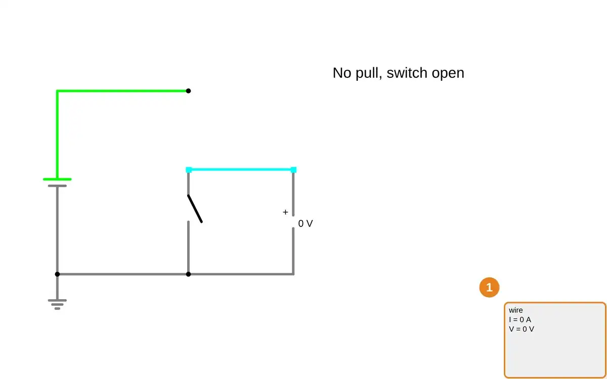
Step 1 · Falstad CircuitJS; numbered callout added to a real capture. Enlarge screenshot (new tab) Step 2
- Do
- Open the 10 kΩ pull-up circuit on the canvas and inspect the node wire with the switch open.
- You will see
- Supply: 5 V DC. Pull-up resistor: R = 10 kΩ. Switch: open. Node wire: V = 5 V. Pull-up resistor: I = 0 A.
- Why it matters
- The resistor creates a defined idle HIGH path while the open switch leaves no ground current path.
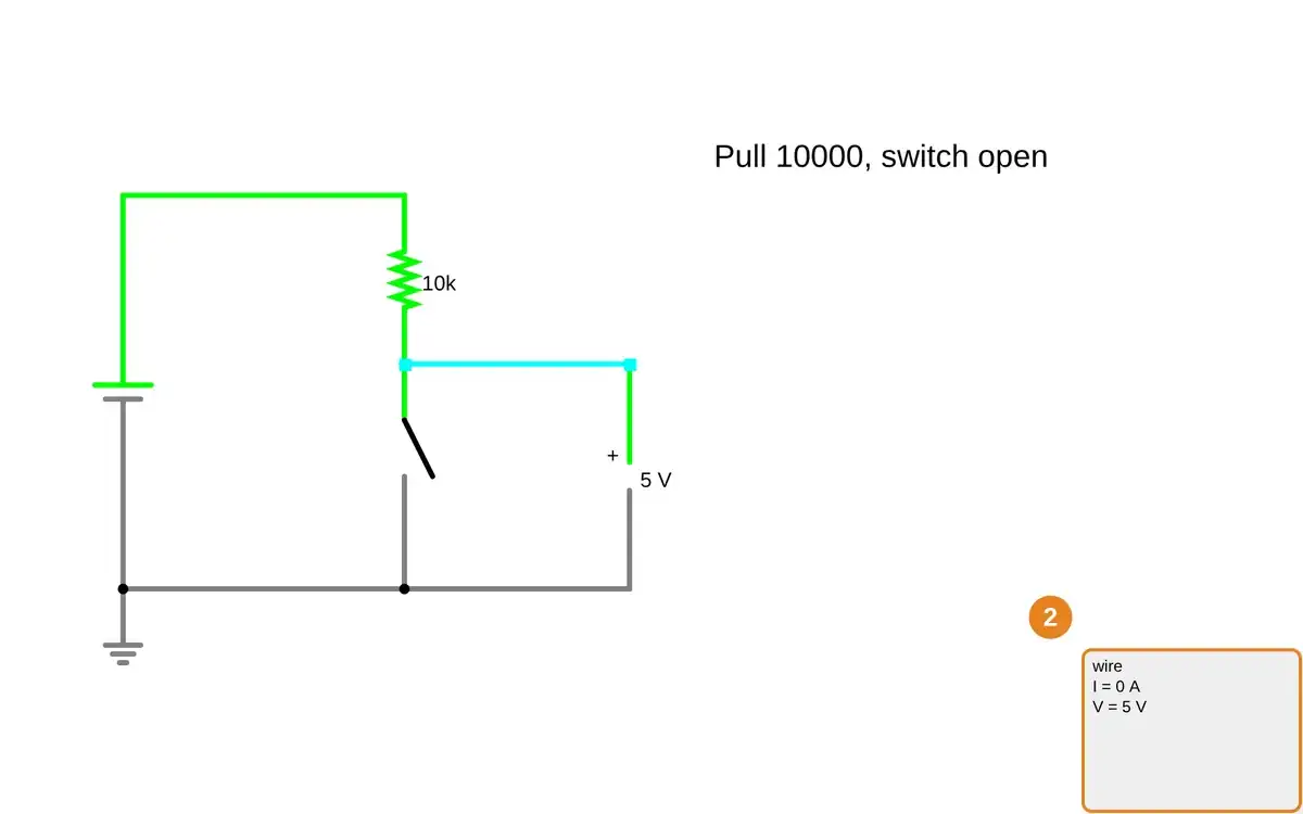
Step 2 · Falstad CircuitJS; numbered callout added to a real capture. Enlarge screenshot (new tab) Step 3
- Do
- Open the 10 kΩ pull-up circuit with the switch closed and point to the resistor on the canvas.
- You will see
- Supply: 5 V DC. Node wire: V = 0 V. Pull-up resistor: R = 10 kΩ. Pull-up resistor: I = 500 μA. Pull-up resistor: Vd = 5 V.
- Why it matters
- Closing the switch pulls the node LOW and makes 5 V / 10 kΩ = 500 μA flow through the pull path.
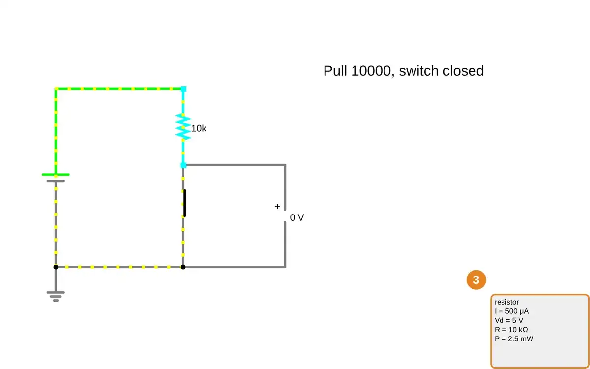
Step 3 · Falstad CircuitJS; numbered callout added to a real capture. Enlarge screenshot (new tab) Step 4
- Do
- Open the 100 kΩ pull-up circuit on the canvas and inspect its resistor with the switch closed.
- You will see
- Supply: 5 V DC. Node wire: V = 0 V. Pull-up resistor: R = 100 kΩ. Pull-up resistor: I = 50 μA. Pull-up resistor: Vd = 5 V.
- Why it matters
- Increasing pull resistance tenfold reduces steady closed-switch current tenfold in this idealized model.
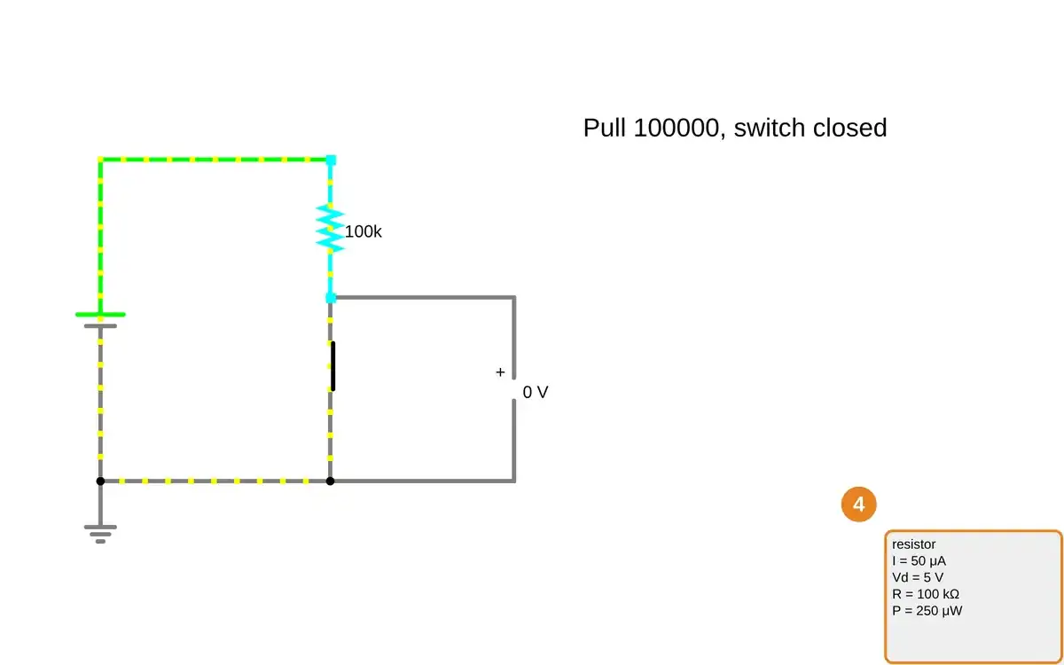
Step 4 · Falstad CircuitJS; numbered callout added to a real capture. Enlarge screenshot (new tab) Step 5
- Do
- Remove the pull resistor by reopening the no-pull circuit on the canvas and inspect the node wire again.
- You will see
- Pull resistor: absent. Switch: open. Wire: I = 0 A. Wire: V = 0 V in CircuitJS. There is still no physical DC pull path.
- Why it matters
- The tool displays a numerical voltage for its floating node, but that value cannot specify a real CMOS input state.
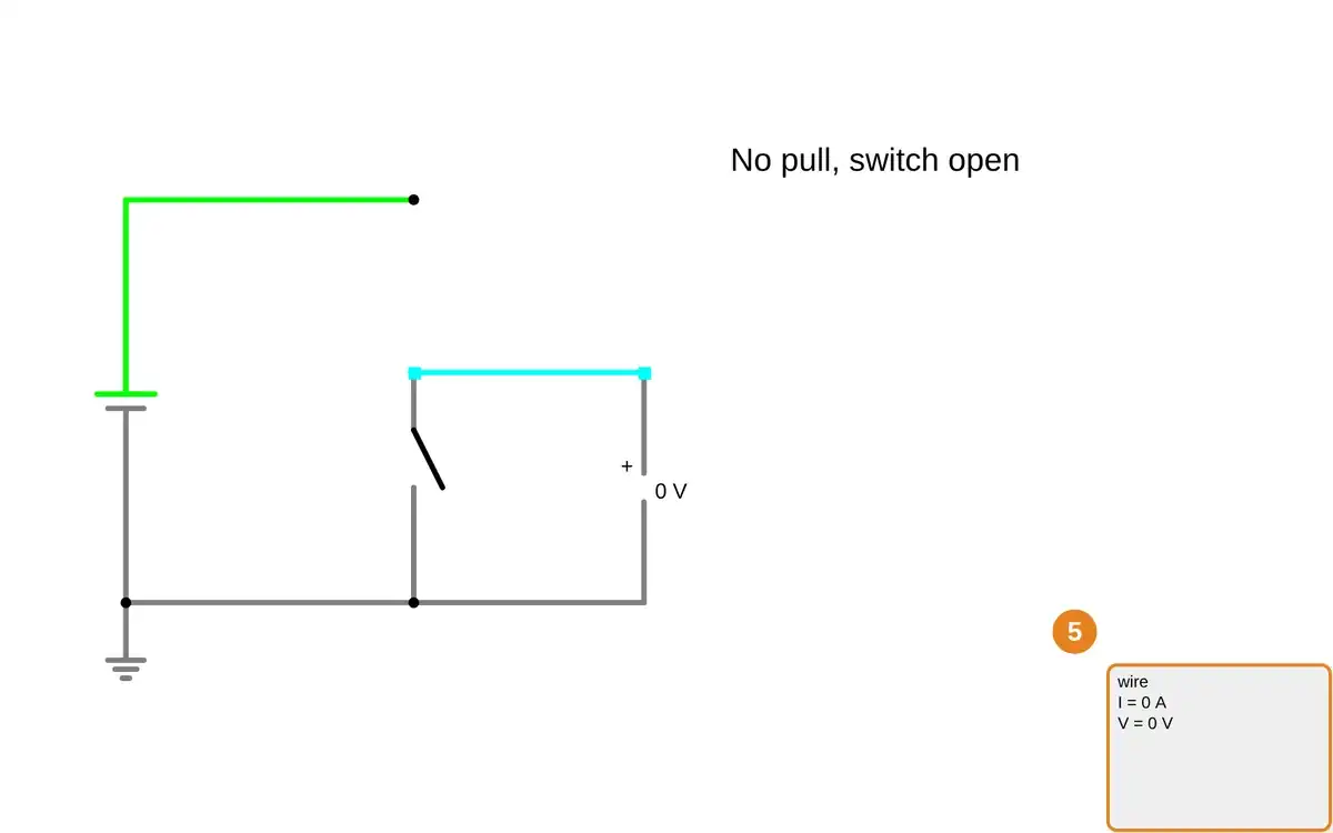
Step 5 · Falstad CircuitJS; numbered callout added to a real capture. Enlarge screenshot (new tab) Step 6
- Do
- Restore the 10 kΩ pull-up circuit on the canvas and inspect the open-switch node readout.
- You will see
- Supply: 5 V DC. Pull-up resistor: R = 10 kΩ. Switch: open. Node wire: V = 5 V. Resistor current: I = 0 A.
- Why it matters
- The real simulator comparison shows which topology defines idle HIGH; it does not establish actual GPIO leakage, noise, or thresholds.
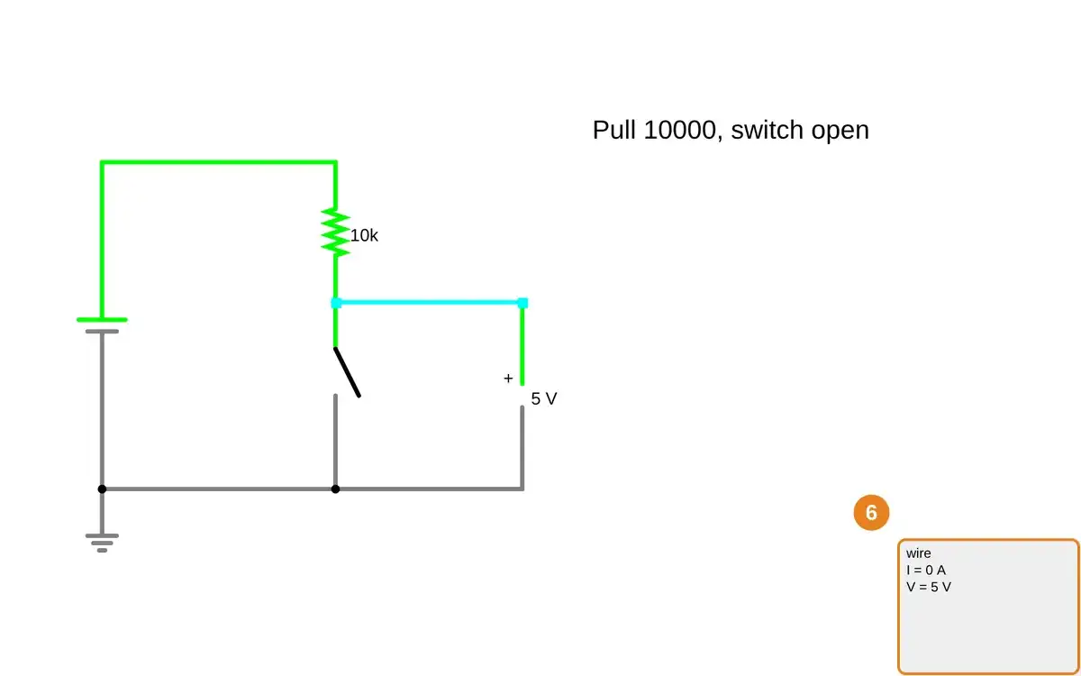
Step 6 · Falstad CircuitJS; numbered callout added to a real capture. Enlarge screenshot (new tab)
Chapter checks
These questions refer to the chapter’s examples. Use the return links to review their answers.
Why does an unused or button-driven CMOS logic input usually need a pull-up or pull-down resistor?
Return to the chapter’s knowledge checkChoosing a pull-up resistor, what is the core trade-off between a strong (small) and a weak (large) value?
Return to the chapter’s knowledge check
Return to Components in Systems: Passive and Active Contracts · Browse Labs