Control a smart-home fan with temperature rules
Inspect two 8 °C automation rules, observe the fan follow the sensor, and safely test a temporary manual override.

Packet Pete
Predict the reading, then compare it with the measurement.
Cisco Packet Tracer
Desktop labInspect two 8 °C automation rules, observe the fan follow the sensor, and safely test a temporary manual override.
Install the tool; build from the steps. No file yet.
Download the Packet Tracer fileSteps
Step 1
- Do
- Packet Tracer Logical workspace: open lab.pkt. Locate Home Gateway0 at the left. Find the wired PC0 below it. Find Temp-Monitor and Fan-Actuator on the right.
- You will see
- The workspace contains one home gateway. PC0 has a wired link to the gateway. A temperature monitor is visible. A fan actuator is visible.
- Why it matters
- The gateway hosts the control rules. PC0 gives you a browser control surface. The monitor supplies the measured input. The fan is the output to check.
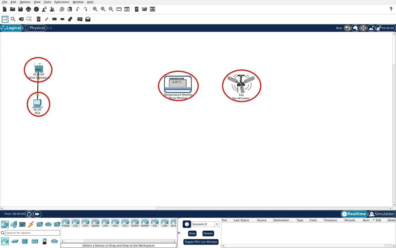
Step 1 · Cisco Packet Tracer; numbered callout added to a real capture. Enlarge screenshot (new tab) Step 2
- Do
- Temp-Monitor Config → Wireless0: open the monitor. Confirm Port Status is On. Read the SSID field. Read its DHCP address if your run shows one.
- You will see
- The captured Wireless0 port is On. The SSID reads HomeGateway. The DHCP selection is active. The captured address is 192.168.25.102.
- Why it matters
- The wireless endpoint must reach the gateway. The SSID identifies the joined network. DHCP supplies a local address. This connection alone does not prove a rule fired.
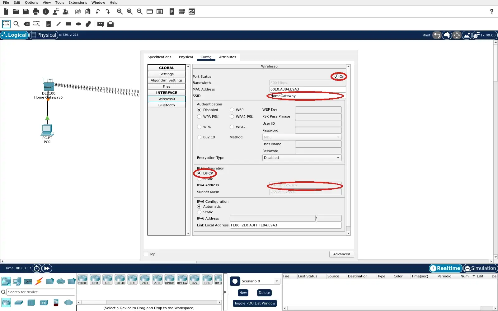
Step 2 · Cisco Packet Tracer; numbered callout added to a real capture. Enlarge screenshot (new tab) Step 3
- Do
- PC0 Desktop → Web Browser: open 192.168.25.1. Sign in if the saved session requires it. Open the gateway Home device view. Expand the monitor and fan rows.
- You will see
- The captured monitor reads 2.4 °C. The fan Status row offers Off, Low and High. Off is selected in the cool capture. The browser is served from 192.168.25.1.
- Why it matters
- The browser shows input and output together. A low reading gives a baseline. The selected button reports fan state. Keep this state for comparison with warm air.
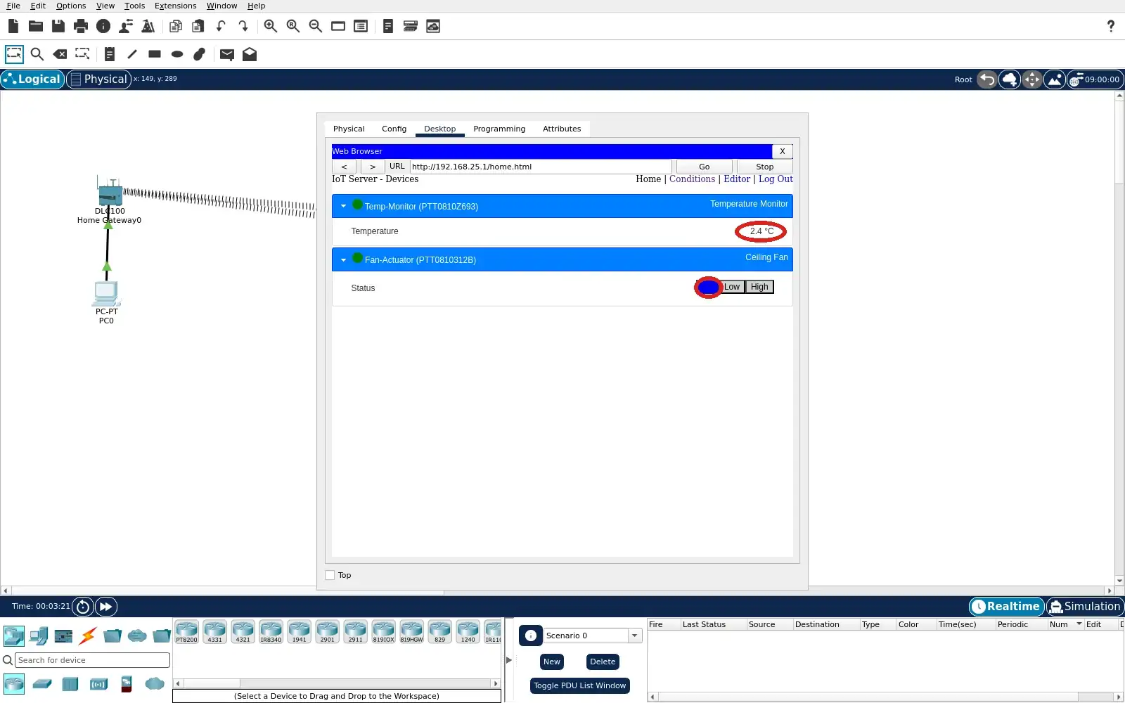
Step 3 · Cisco Packet Tracer; numbered callout added to a real capture. Enlarge screenshot (new tab) Step 4
- Do
- PC0 Desktop → Web Browser → Conditions: open the rule list. Read the Warm air starts fan row. Read the Cool air stops fan row. Check that both Enabled cells say Yes.
- You will see
- Warm air uses Temperature > 8.0 °C. Its action sets Fan-Actuator High. Cool air uses Temperature <= 8.0 °C. Its action sets the fan Off; both are enabled.
- Why it matters
- The two inequalities cover either side of 8 °C. The actions define the intended fan state. Enabled confirms the rules are active. The rule list is the control logic evidence.
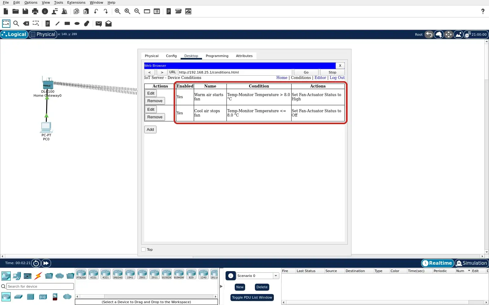
Step 4 · Cisco Packet Tracer; numbered callout added to a real capture. Enlarge screenshot (new tab) Step 5
- Do
- Packet Tracer Environment editor: open Main Wiring Closet. Expand Temperature in the variable list. Find the Ambient Temperature row. Inspect the initial value and graph controls.
- You will see
- Ambient Temperature is shown in the editor. The captured initial value is 20 °C. Interpolation and Show are checked. A separate PT graph can display its curve.
- Why it matters
- Environment variables drive the simulator. An initial value is configuration evidence. The graph alone does not prove a rule fired. Use the browser state to check the actual result.
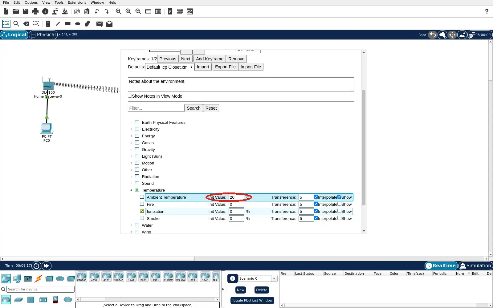
Step 5 · Cisco Packet Tracer; numbered callout added to a real capture. Enlarge screenshot (new tab) Step 6
- Do
- PC0 Desktop → Web Browser → Home: keep both rules enabled. Allow the environment clock to advance. Watch the Temp-Monitor reading. Check the fan button as air passes 8 °C.
- You will see
- The captured warm reading is 10.9 °C. High is selected for Fan-Actuator. A prior capture in this run showed 3.8 °C and Off. The same rule pair remained enabled.
- Why it matters
- The measured input has crossed the threshold. High matches the warm rule action. The paired cool state supports the cycle check. A browser result is stronger than a rule definition alone.
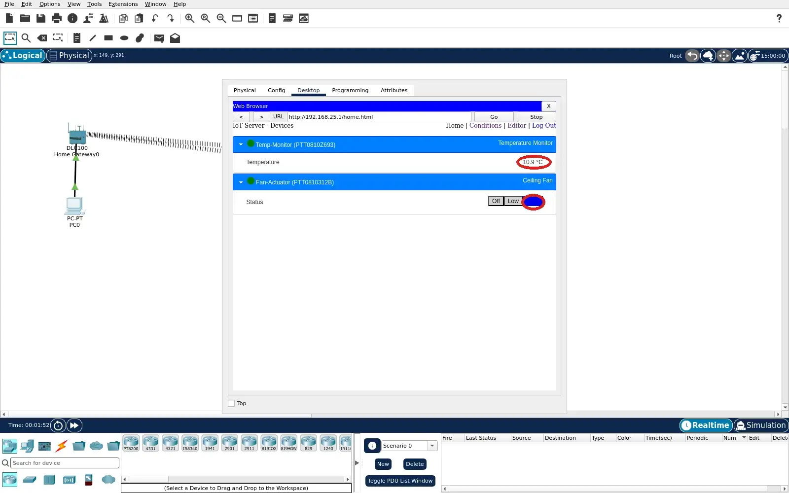
Step 6 · Cisco Packet Tracer; numbered callout added to a real capture. Enlarge screenshot (new tab) Step 7
- Do
- PC0 Desktop → Web Browser → Conditions: edit the cool rule. Temporarily set Cool air stops fan to Disabled. Return to the Conditions list. Confirm only its Enabled cell says No.
- You will see
- Warm air starts fan remains Yes. Cool air stops fan reads No. The cool condition still reads <= 8.0 °C. Its action is still written as Off.
- Why it matters
- Pausing the stop rule permits a manual override. It avoids immediate automatic correction. The warm rule stays available. Restore the stop rule after the experiment.
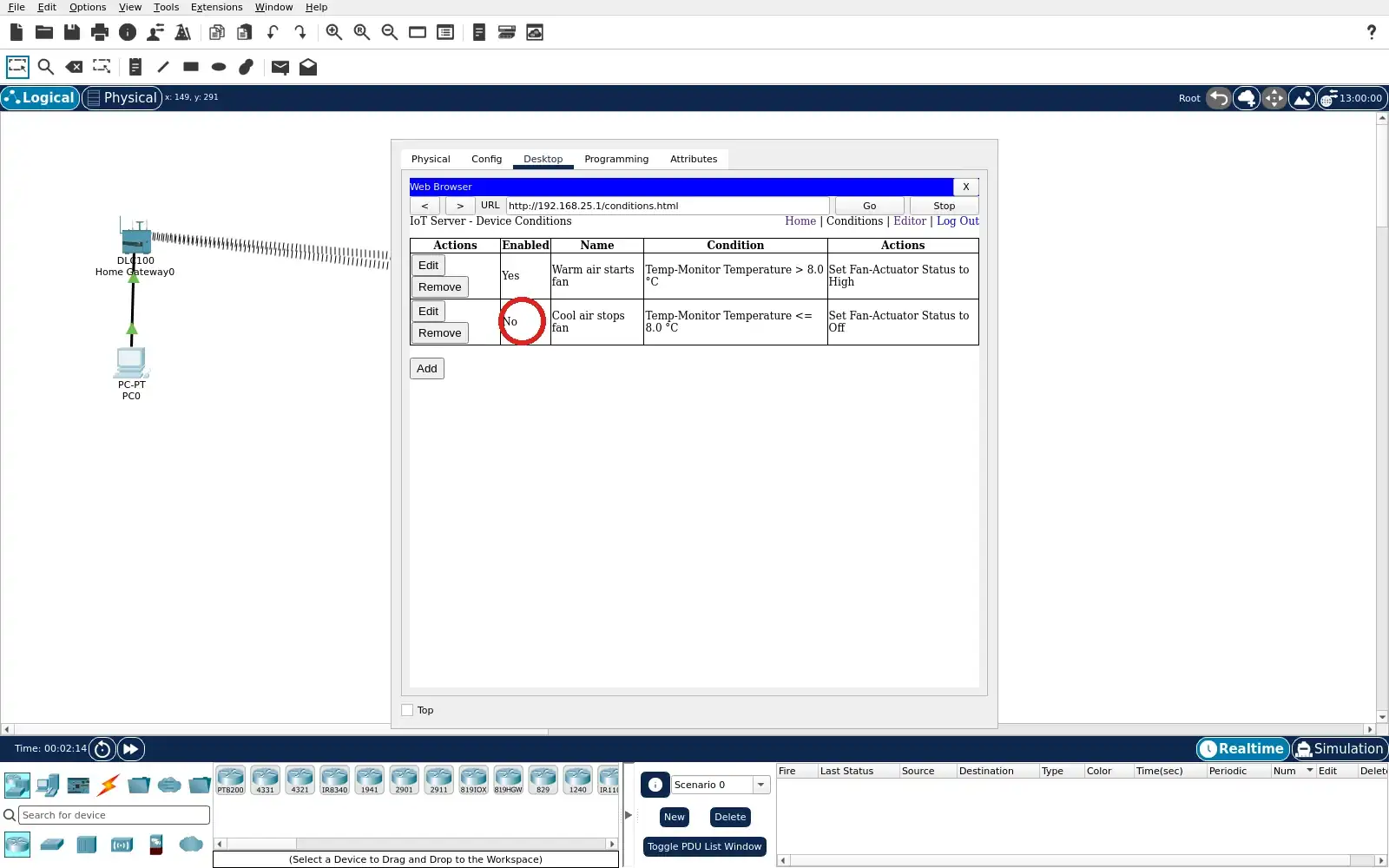
Step 7 · Cisco Packet Tracer; numbered callout added to a real capture. Enlarge screenshot (new tab) Step 8
- Do
- PC0 Desktop → Web Browser → Home: wait below 8 °C. Expand the Fan-Actuator row in the browser. Click the High button while the cool rule is paused. Read the resulting temperature and Status.
- You will see
- The captured temperature is 4.0 °C. High is selected after the manual click. The cool stop rule was disabled before this action. This is a deliberate manual override.
- Why it matters
- Manual control demonstrates authority at the browser. The cool reading makes the override visible. The rule pause prevents an immediate Off action. The setting is temporary for this exercise.
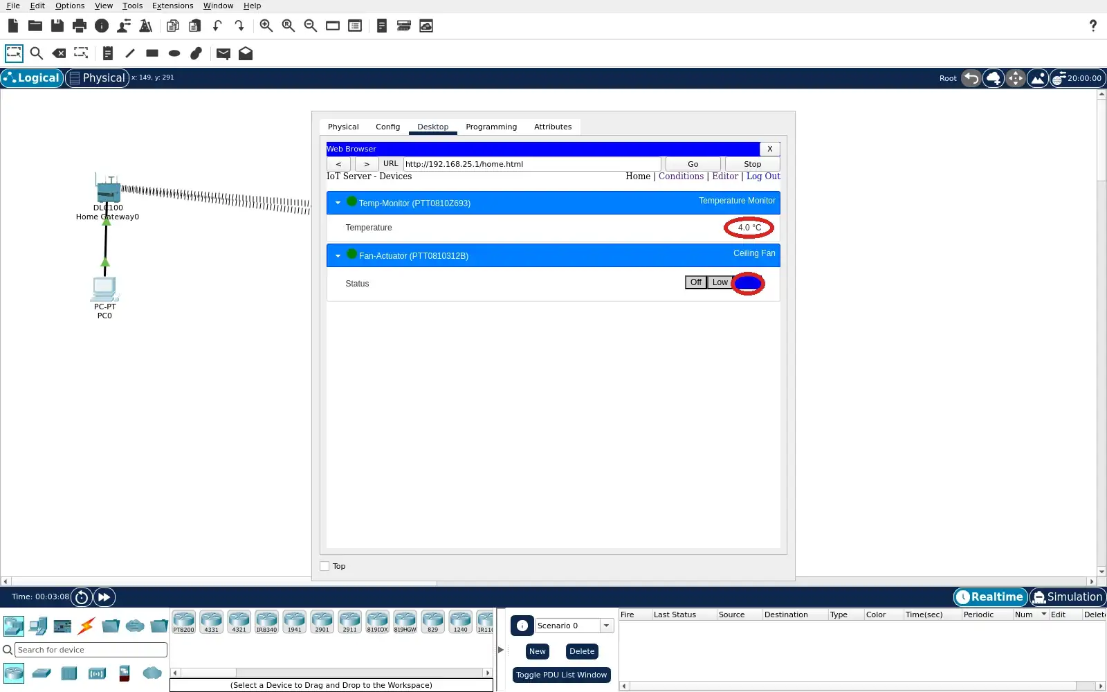
Step 8 · Cisco Packet Tracer; numbered callout added to a real capture. Enlarge screenshot (new tab) Step 9
- Do
- PC0 Desktop → Web Browser → Conditions: reopen the cool rule. Set its Enabled field back to Yes. Verify both rows in the Conditions list. Save the Packet Tracer project.
- You will see
- Both Enabled cells read Yes in the capture. The warm rule still uses > 8.0 °C. The cool rule still uses <= 8.0 °C. The saved learner file retains this rule pair.
- Why it matters
- Restoring the rule ends the override. The next cool reading can turn the fan Off. Saving preserves the safe exercise baseline. Reopen the file before reusing it.
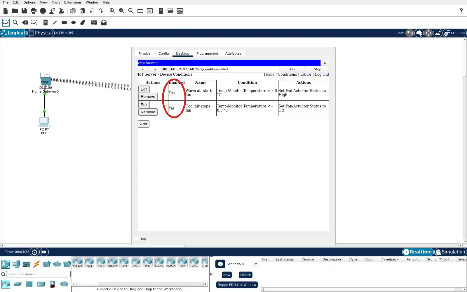
Step 9 · Cisco Packet Tracer; numbered callout added to a real capture. Enlarge screenshot (new tab)
Chapter checks
These questions refer to the chapter’s examples. Use the return links to review their answers.
A home’s app becomes unavailable while a guest needs the lights. Which design best meets the chapter’s livability principle?
Return to the chapter’s knowledge checkTwo home controllers can issue commands to the same device. What should the design record make explicit?
Return to the chapter’s knowledge check
Return to Smart Home: Needs, Protocols, and Boundaries · Browse Labs