Smart Cities: Parking and Governance
Trigger one simulated bay signal, verify its local indicator and gateway view, then observe how a disconnected operator path makes that view stale or unavailable.

Packet Pete
Predict the reading, then compare it with the measurement.
Cisco Packet Tracer
Desktop labTrigger one simulated bay signal, verify its local indicator and gateway view, then observe how a disconnected operator path makes that view stale or unavailable.
Install the tool; build from the steps. No file yet.
Download the Packet Tracer fileSteps
Step 1
- Do
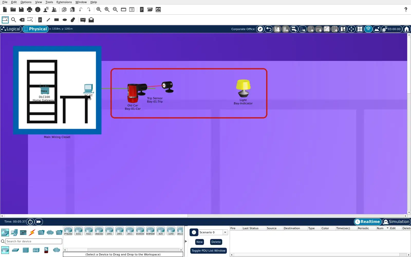
- Open lab.pkt in Packet Tracer and choose the Physical tab. Locate Home City, then the Corporate Office location. Find Bay-01-Car, Bay-01-Trip and Bay-Indicator together. Use Logical to inspect their network connections afterward.
- You will see
- The Physical view shows the car beside the Trip Sensor. Bay-Indicator is to their right in the same location. Home Gateway0 and PC0 appear in the wiring closet. The location bar reads Corporate Office.
- Why it matters
- These three objects define one simulated observation bay. The car icon gives context but does not actuate the sensor. The gateway and PC identify the reporting consumer path. One bay state must not be described as a citywide count.
Step 1 · Cisco Packet Tracer; numbered callout added to a real capture. Enlarge screenshot (new tab) Step 2
- Do
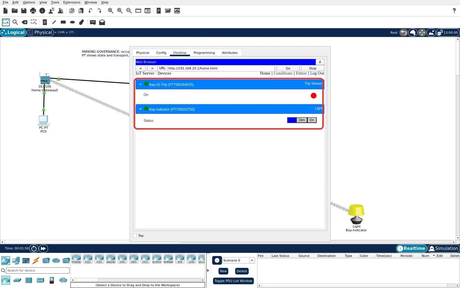
- On PC0, open the Desktop tab and Web Browser. Visit http://192.168.25.1 and sign in with admin/admin. Open the gateway Devices page with the beam clear. Record the Trip Sensor and indicator baseline.
- You will see
- The gateway page lists Bay-01-Trip and Bay-Indicator. The Trip Sensor status dot is red in the clear state. The indicator's Off selection is blue. Both readings appear in the operator browser.
- Why it matters
- A baseline makes the later change interpretable. The remote page is a simulated operator view. The sensor and light should agree before fault injection. A displayed state also needs a freshness check.
Step 2 · Cisco Packet Tracer; numbered callout added to a real capture. Enlarge screenshot (new tab) Step 3
- Do
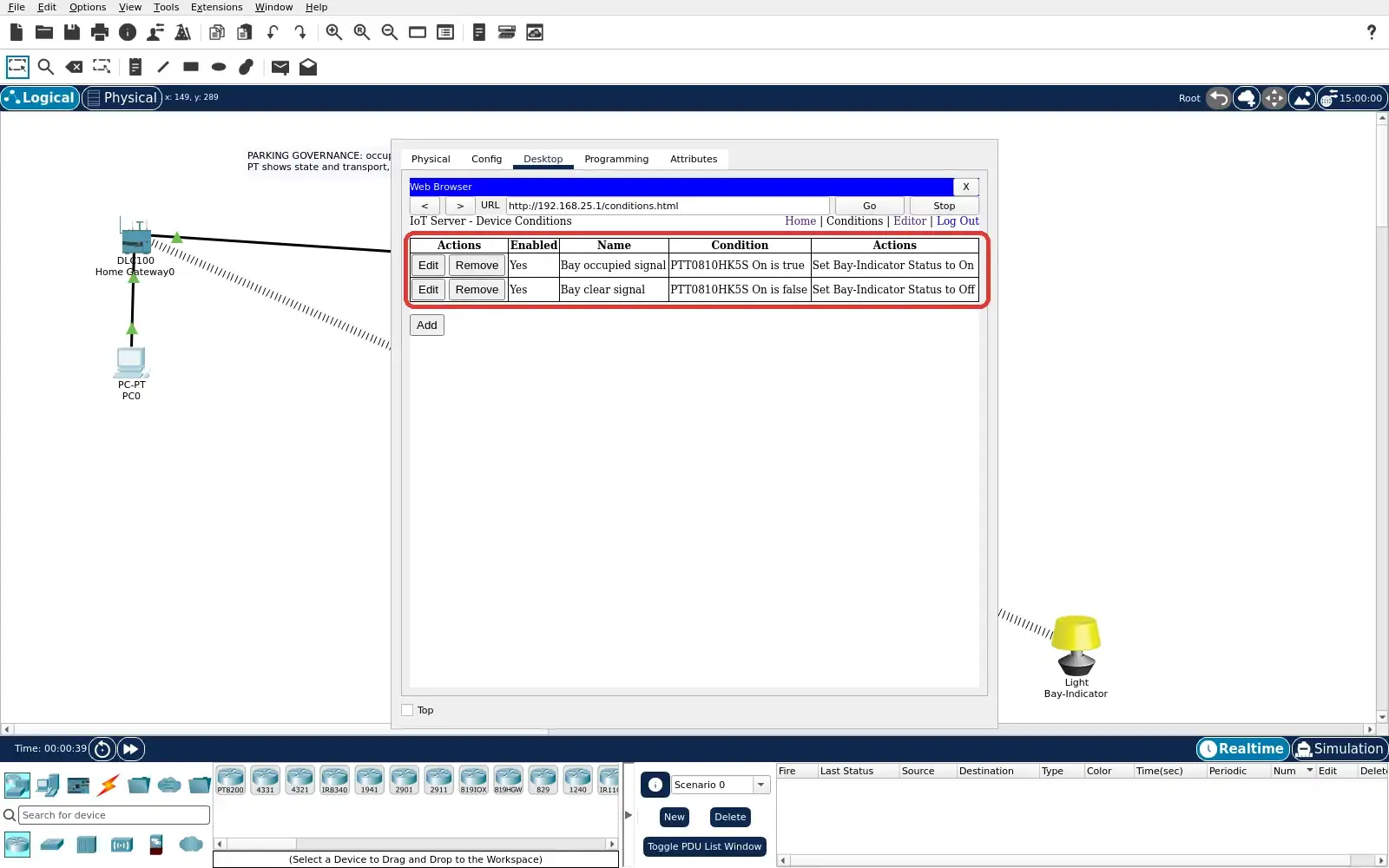
- In the gateway browser, open the Conditions tab. Find the Bay occupied signal rule. Find the Bay clear signal rule below it. Read both the Trip Sensor test and light action.
- You will see
- Bay occupied signal tests Bay-01-Trip On is true. Its action sets Bay-Indicator Status to On. Bay clear signal tests Bay-01-Trip On is false. Its action sets Bay-Indicator Status to Off.
- Why it matters
- The light is driven by explicit gateway logic. The two rules map one binary signal to two states. This is a local simulator rule, not a city policy. The operator can audit the mapping before trusting a display.
Step 3 · Cisco Packet Tracer; numbered callout added to a real capture. Enlarge screenshot (new tab) Step 4
- Do
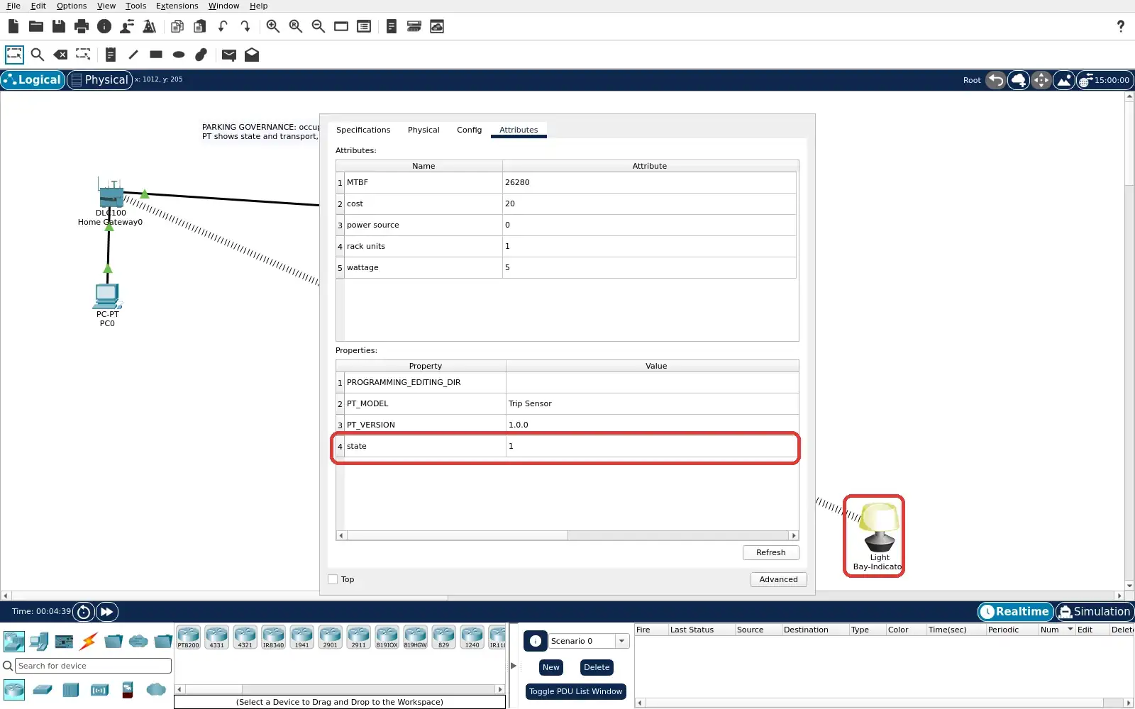
- Return to Logical and open Bay-01-Trip. Choose the Attributes tab to read its state. Hold Alt and move the pointer across the sensor beam. Watch the Trip Sensor dot and state field change.
- You will see
- The Trip Sensor Attributes state reads 1. A lit dot appears on the sensor after the beam event. Bay-Indicator is visibly lit in the canvas. The car remains a separate visual object.
- Why it matters
- The state field proves the simulated event source. The rule converts that source into a local indication. Alt-pointer motion is PT's supported Trip Sensor input. Moving the car graphic alone did not provide this evidence.
Step 4 · Cisco Packet Tracer; numbered callout added to a real capture. Enlarge screenshot (new tab) Step 5
- Do
- On PC0, return to the gateway Devices list. Refresh it after the beam event if necessary. Compare Bay-01-Trip with Bay-Indicator. Record the operator's occupied state before any fault.
- You will see
- Bay-01-Trip has a green status indicator. Bay-Indicator's rightmost On selection is blue. The local indicator graphic is lit on the canvas. The browser and local signal agree at this moment.
- Why it matters
- The operator sees the mapped event through the gateway. Agreement shows the reporting path works while connected. The browser is a consumer, not the source of the event. Its cached contents can later outlive the connection.
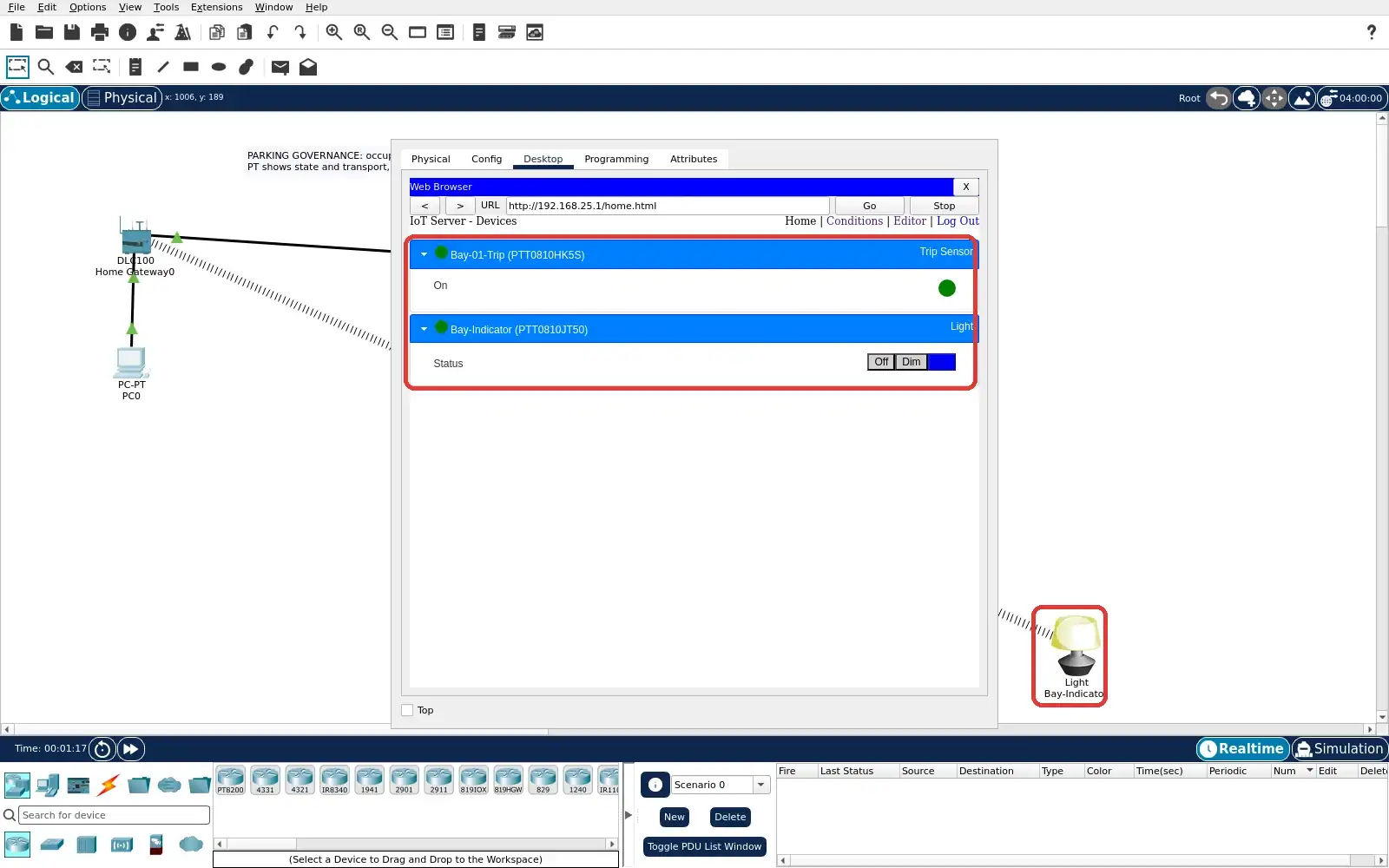
Step 5 · Cisco Packet Tracer; numbered callout added to a real capture. Enlarge screenshot (new tab) Step 6
- Do
- Open the PC0 Config tab and select FastEthernet0. Turn Port Status Off to break the operator path. Confirm the PC-to-gateway cable markers turn red. Keep the sensor and indicator locally active.
- You will see
- PC0 FastEthernet0 Port Status is unchecked. The wired path to Home Gateway0 shows red markers. The Trip Sensor and indicator remain on the canvas. Only the PC reporting path has been disabled.
- Why it matters
- This is a specific, repeatable network fault. It isolates the operator from a still local rule. A failed browser connection does not prove sensor failure. The precise fault matters when interpreting stale data.
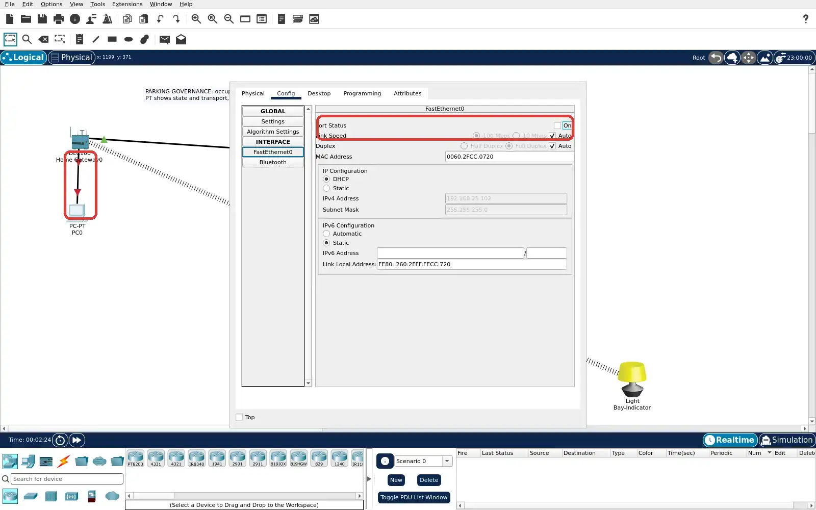
Step 6 · Cisco Packet Tracer; numbered callout added to a real capture. Enlarge screenshot (new tab) Step 7
- Do
- With PC0 disconnected, Alt-move across the beam again. Observe the local Bay-Indicator change. Return to the already open gateway browser tab. Compare its cached state with the physical light.
- You will see
- The local bay indicator is lit after the beam event. The disconnected browser still shows Trip Sensor red. Its cached Bay-Indicator selection remains Off. The PC-to-gateway link marker is red.
- Why it matters
- The local rule continues to react to the sensor. The disconnected operator page has an older state. Without a freshness cue, Off could mislead a user. This is observed staleness, not a live occupancy count.
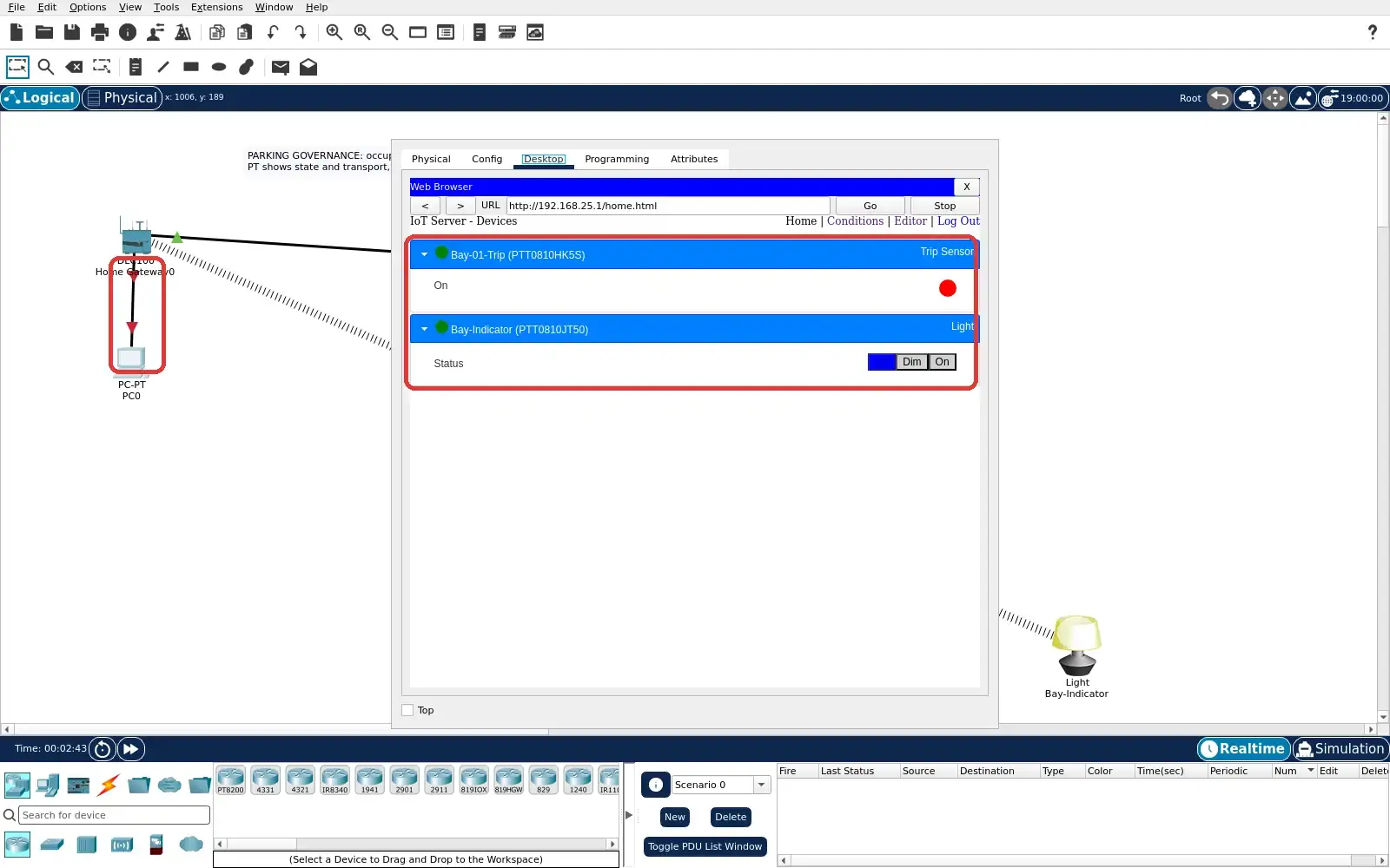
Step 7 · Cisco Packet Tracer; numbered callout added to a real capture. Enlarge screenshot (new tab) Step 8
- Do
- Keep PC0 FastEthernet0 Off. Refresh the gateway page in its Web Browser tab. Wait for Packet Tracer's response. Record the error rather than inferring a new bay state.
- You will see
- The PT browser URL remains http://192.168.25.1. The content area says Request Timeout. The PC-to-gateway cable markers remain red. No current bay value is delivered to this browser.
- Why it matters
- A timeout is evidence of missing remote data. It is not evidence that the bay became clear. Operators should flag the view as unavailable or stale. The local controller may still hold a valid state.
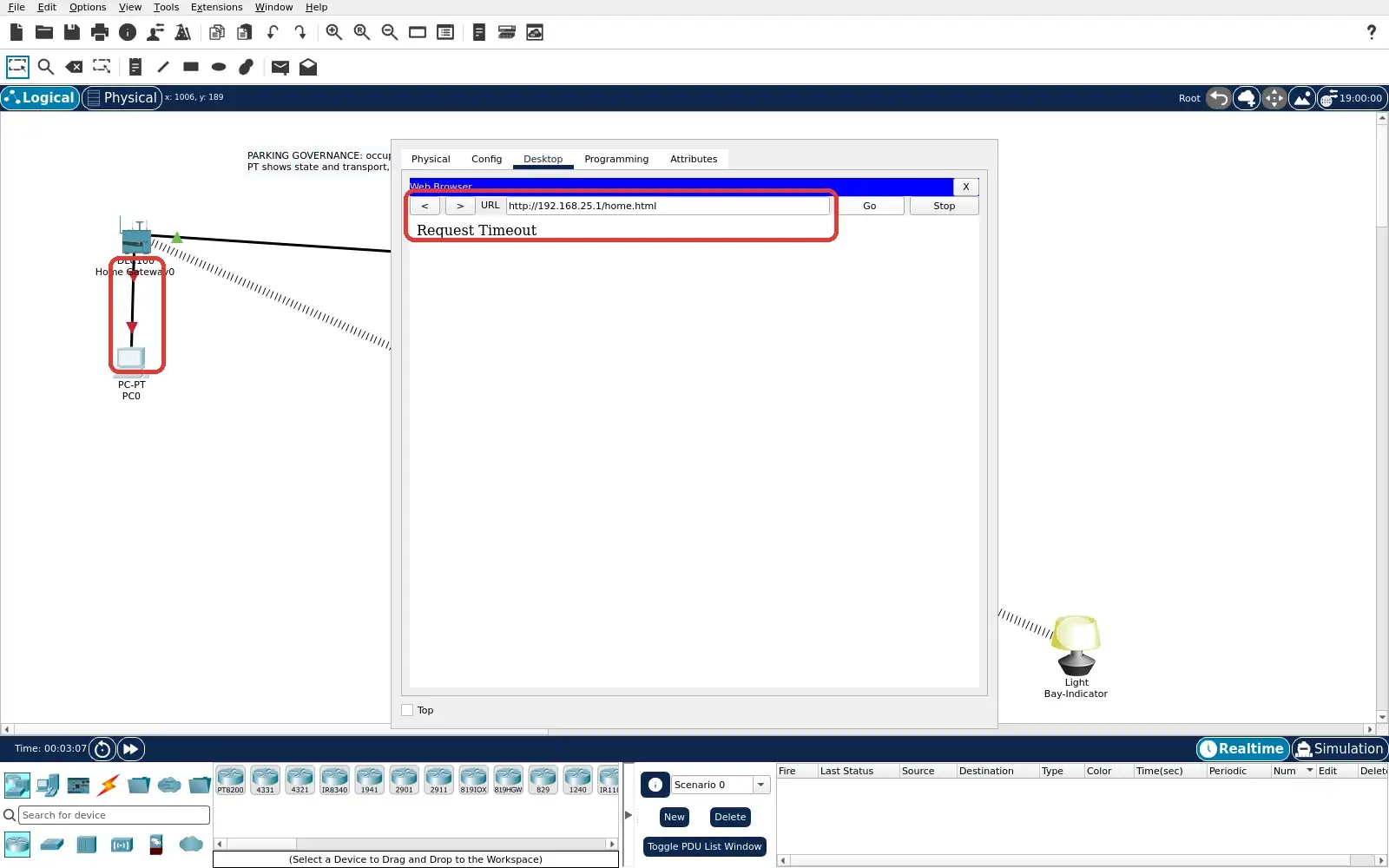
Step 8 · Cisco Packet Tracer; numbered callout added to a real capture. Enlarge screenshot (new tab) Step 9
- Do
- Turn PC0 FastEthernet0 Port Status back On. Allow DHCP and the wired link to settle. Reload http://192.168.25.1 and sign in if asked. Verify the Devices list returns; leave the beam clear.
- You will see
- The PT browser again lists Bay-01-Trip. Bay-Indicator is also back in the Devices list. The PC-to-gateway link markers are green. The screen shows a fresh gateway page after recovery.
- Why it matters
- Restoring transport lets the operator fetch a new view. The page must be reloaded before trusting its state. Recovery does not validate a real parking service. The exercise ends with the operator path restored.
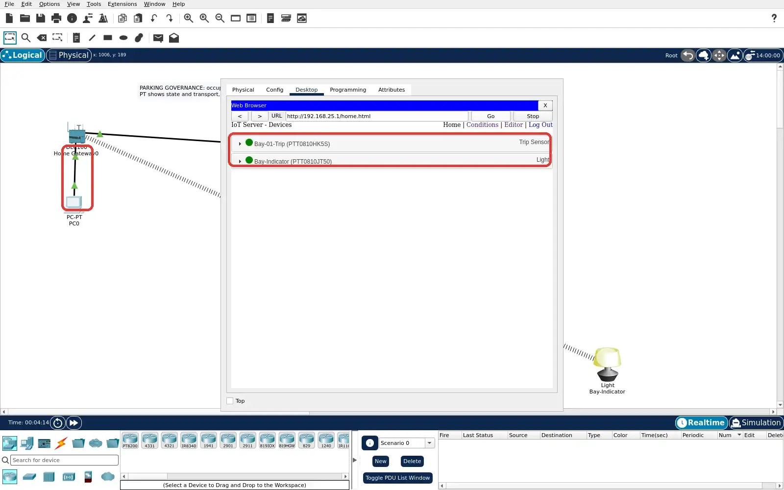
Step 9 · Cisco Packet Tracer; numbered callout added to a real capture. Enlarge screenshot (new tab)
Chapter checks
These questions refer to the chapter’s examples. Use the return links to review their answers.
Per this chapter, when is a city sensor deployment still just an 'instrumentation pilot' rather than a smart-city service?
Return to the chapter’s knowledge checkPer this chapter's integration-contract guidance, what should happen to the public and operator view when a LoRaWAN gateway goes down or an air-quality sensor drifts after calibration expires?
Return to the chapter’s knowledge check
Return to Smart Cities: Parking and Governance · Browse Labs