IoT VLAN boundary and one required service
Map three VLANs, permit one operator HTTP service flow into the IoT-service zone, and prove a different routed flow is denied.
Packet Pete
Predict the reading, then compare it with the measurement.
Cisco Packet Tracer
Desktop labMap three VLANs, permit one operator HTTP service flow into the IoT-service zone, and prove a different routed flow is denied.
Install the tool; build from the steps. No file yet.
Download the Packet Tracer fileSteps
Step 1
- Do
- Open lab.pkt in Packet Tracer Logical canvas. Wait for the switch links to turn green after startup. Find VLAN-Gateway, VLAN-Switch, PC0, PC1, PC2 and Server0. Trace IoT-Fan through Wireless Router0 toward VLAN-Switch.
- You will see
- The canvas shows a 2911 labeled VLAN-Gateway. A 2960 labeled VLAN-Switch has six wired paths. IoT-Fan has a dotted link to Wireless Router0. The router, switch, PCs and server show green link markers.
- Why it matters
- The diagram identifies devices before interpreting traffic. PC0 and Server0 will be the local IoT-service baseline. PC1 is the operator; PC2 is the unrelated client. The dotted radio link is association evidence, not a VLAN test.
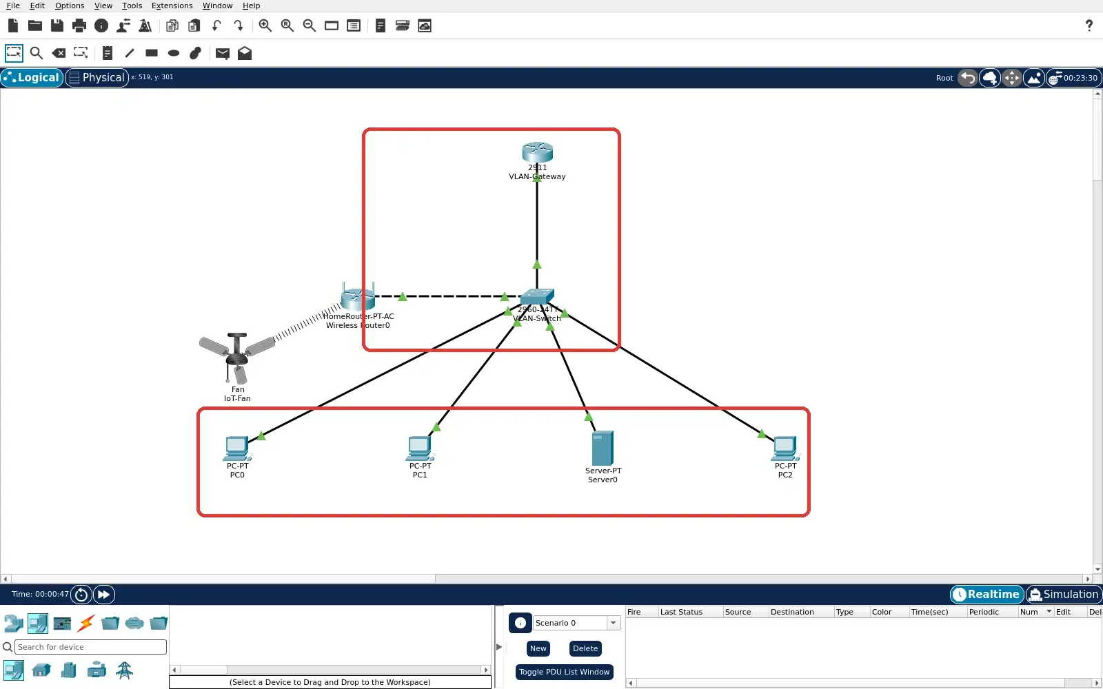
Step 1 · Cisco Packet Tracer; numbered callout added to a real capture. Enlarge screenshot (new tab) Step 2
- Do
- Open IoT-Fan, choose Advanced, then Config and Wireless0 tab. Read the SSID, authentication and encryption settings. Check Port Status and the static IPv4 fields. Compare this network identity with Wireless Router0 2.4 GHz.
- You will see
- Wireless0 Port Status is On and SSID reads IoT-DeviceNet. WPA2-PSK is selected with the exercise passphrase shown. Encryption Type reads AES. Static IPv4 reads 10.10.10.30 with mask 255.255.255.0.
- Why it matters
- The Thing has a separate radio admission setting. Its address belongs to the modeled IoT-service subnet. Wireless credentials alone do not enforce the VLAN boundary. The router rule and packet results must provide that proof.
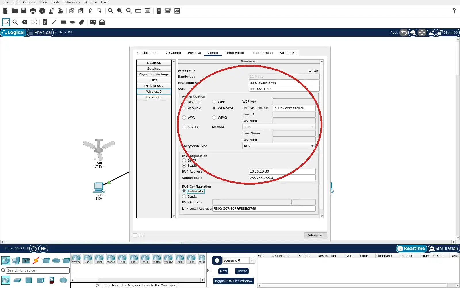
Step 2 · Cisco Packet Tracer; numbered callout added to a real capture. Enlarge screenshot (new tab) Step 3
- Do
- Open VLAN-Switch and select the CLI tab. Run show vlan brief to read each access-port group. Locate the Fa0/1 trunk configuration above the result. Match each port group to the connected devices.
- You will see
- VLAN 10 IOT_SERVICE lists Fa0/2, Fa0/3 and Fa0/5. VLAN 20 OPERATOR lists Fa0/4. VLAN 30 UNRELATED lists Fa0/6. The CLI shows Fa0/1 configured as a trunk for 10,20,30.
- Why it matters
- The port list makes zone membership testable. The server, IoT-side PC and wireless router use VLAN 10. The operator and unrelated PC occupy different VLANs. A VLAN label still needs a routed policy and traffic checks.
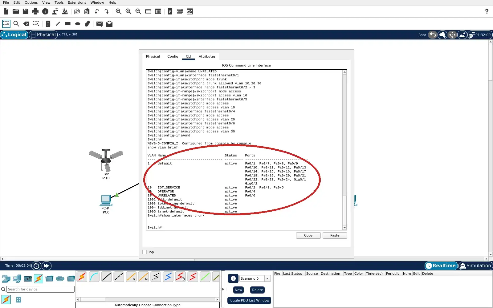
Step 3 · Cisco Packet Tracer; numbered callout added to a real capture. Enlarge screenshot (new tab) Step 4
- Do
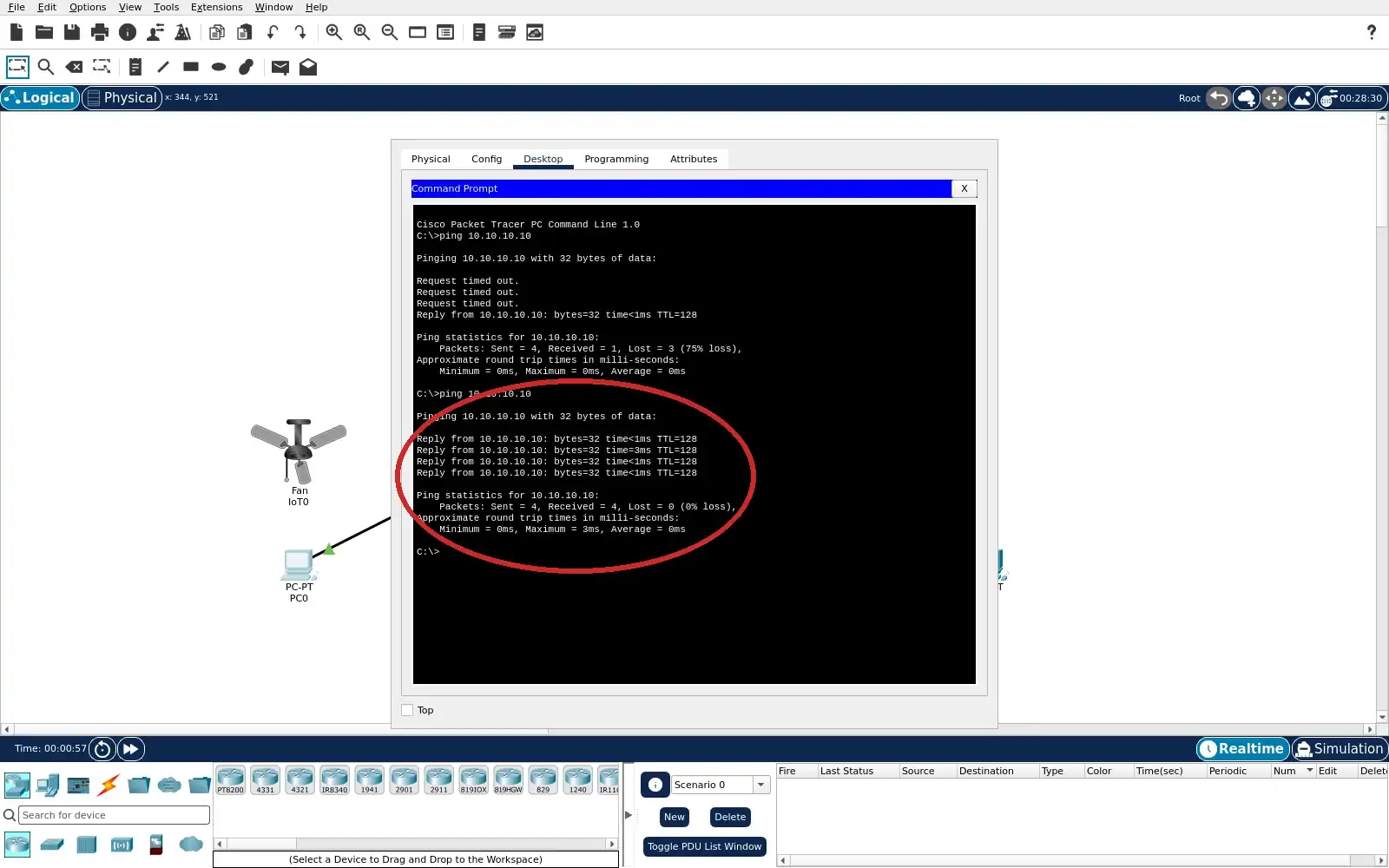
- On PC0, open Desktop and Command Prompt. Run ping 10.10.10.10 toward Server0. If early requests time out while links settle, repeat it. Record the complete second result, including packet loss.
- You will see
- The first visible attempt lost three of four packets. The repeated ping targets 10.10.10.10 again. Four replies from 10.10.10.10 are visible. The second statistics line says Received = 4, Lost = 0.
- Why it matters
- This is a positive same-VLAN service-side baseline. The screenshot preserves the startup loss rather than hiding it. Repeating after the simulated links settle gives a stable result. Same-VLAN reachability does not prove cross-zone permission.
Step 4 · Cisco Packet Tracer; numbered callout added to a real capture. Enlarge screenshot (new tab) Step 5
- Do
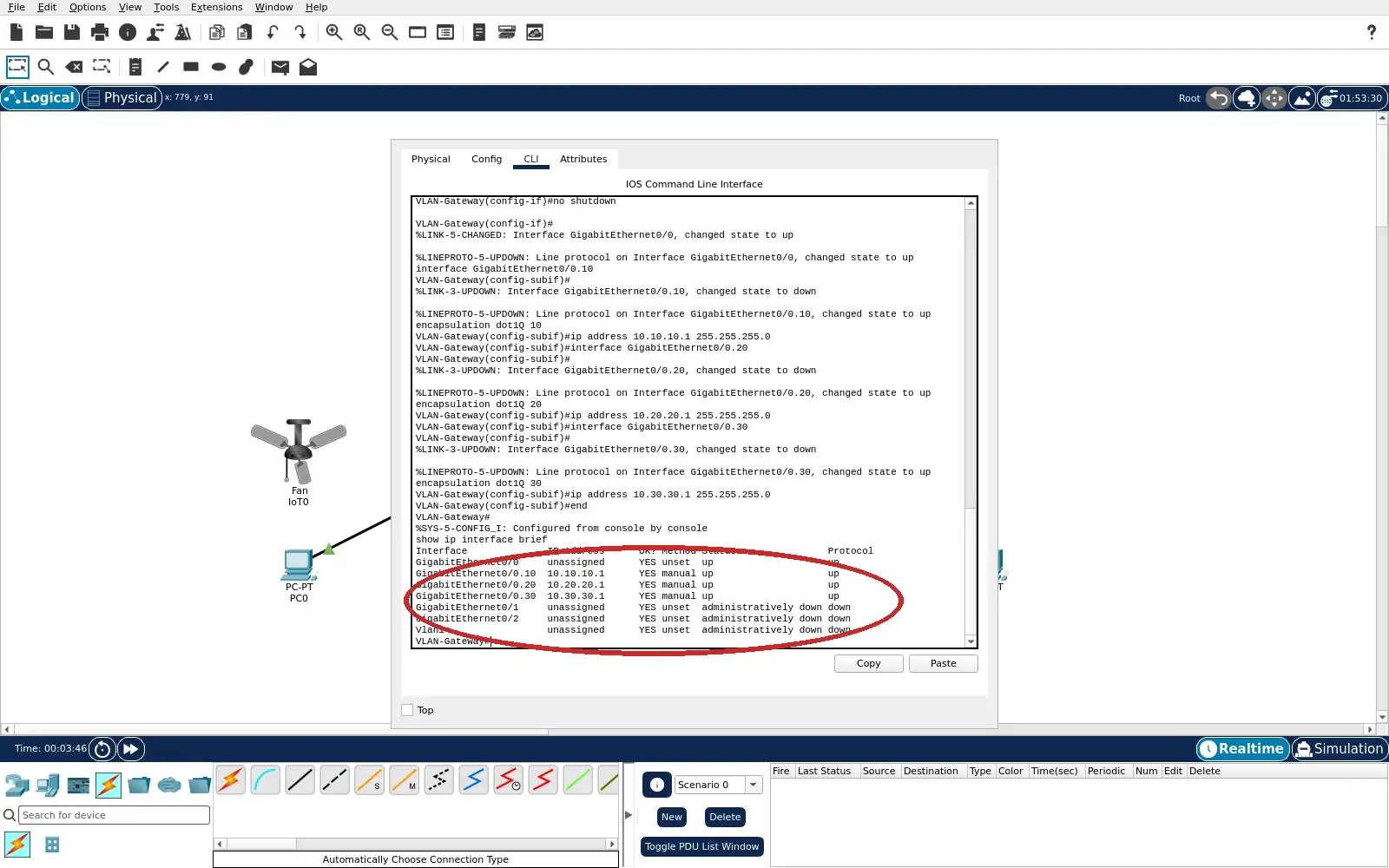
- Open VLAN-Gateway CLI tab and run show ip interface brief. Read the three 802.1Q subinterface addresses. Check both Status and Protocol for each subinterface. Keep these gateway addresses with the VLAN map.
- You will see
- GigabitEthernet0/0.10 shows 10.10.10.1. GigabitEthernet0/0.20 shows 10.20.20.1. GigabitEthernet0/0.30 shows 10.30.30.1. All three rows show up for Status and Protocol.
- Why it matters
- The trunk carries three routed subnet gateways. Routing is required before a cross-VLAN permit can be tested. The addresses identify where a rule can be attached. An up interface by itself says nothing about allowed flows.
Step 5 · Cisco Packet Tracer; numbered callout added to a real capture. Enlarge screenshot (new tab) Step 6
- Do
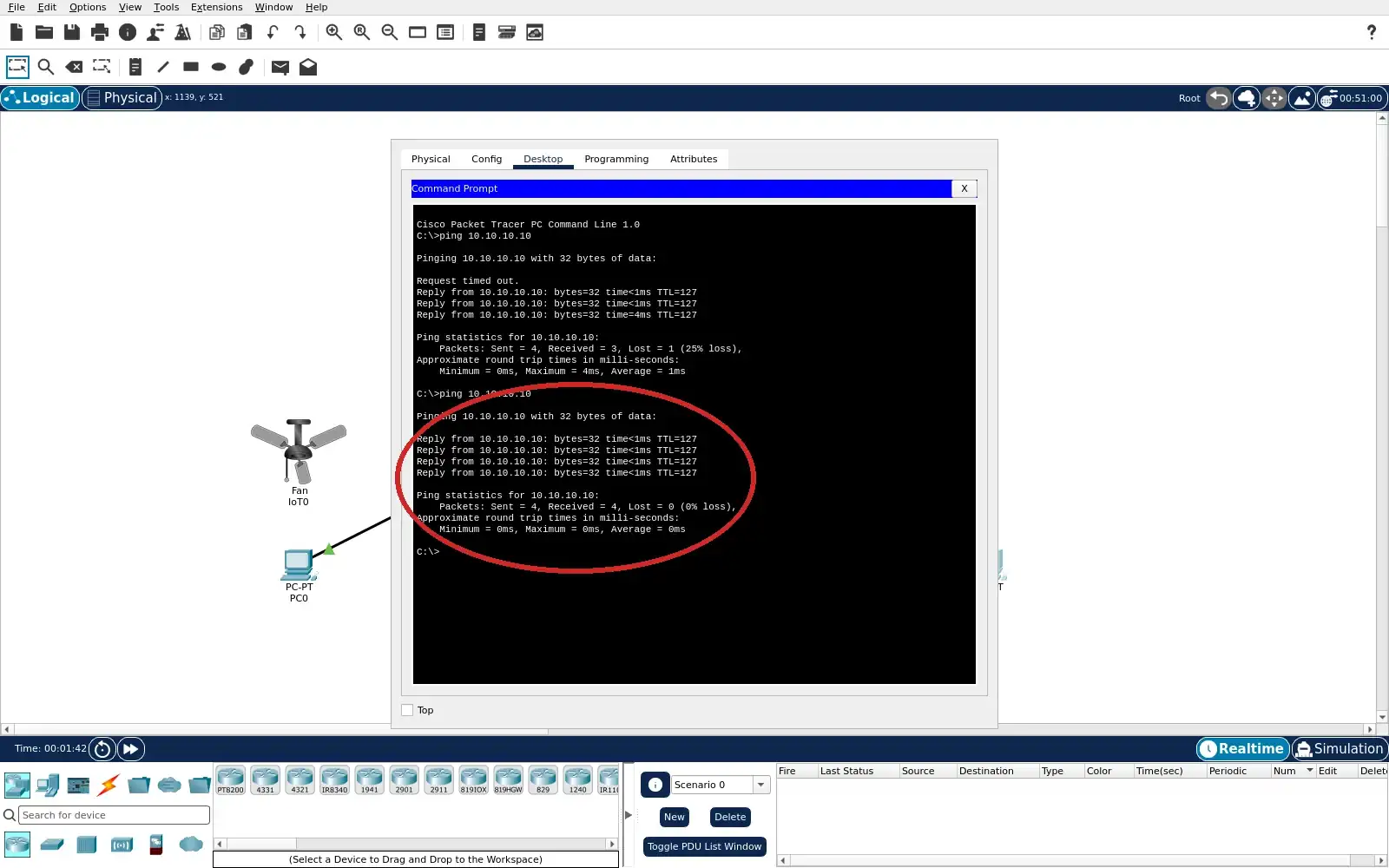
- Before applying ACL 110, use PC2 Command Prompt. In the saved project, remove ACL 110 from G0/0.10 out first. Run ping 10.10.10.10; repeat after startup if needed. Restore the ACL in the next step before leaving the lab.
- You will see
- The first visible attempt has one timeout and three replies. A second PC2 ping receives four replies from 10.10.10.10. The second statistics line reports Received = 4, Lost = 0. The reply TTL is 127, consistent with a routed path in PT.
- Why it matters
- This records unintended exposure before the rule. The positive result makes the later deny meaningful. The temporary removal is only for the exercise comparison. It must be reversed before the project is saved.
Step 6 · Cisco Packet Tracer; numbered callout added to a real capture. Enlarge screenshot (new tab) Step 7
- Do
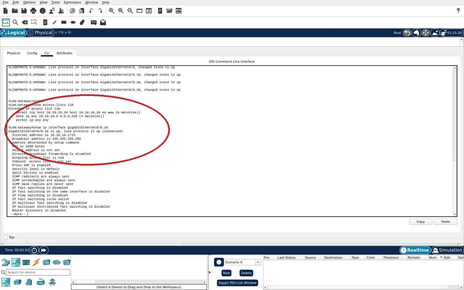
- On VLAN-Gateway CLI tab, inspect ACL 110 and G0/0.10. Restore ip access-group 110 out on that subinterface. Read the ordered HTTP permit and subnet deny entries. Use show ip interface to confirm the outbound binding.
- You will see
- ACL 110 permits TCP from 10.20.20.20 to 10.10.10.10 eq www. The next entry denies IP traffic toward 10.10.10.0/24. GigabitEthernet0/0.10 is up with address 10.10.10.1/24. Its Outgoing access list is 110.
- Why it matters
- The operator exception names source, destination and port. The deny follows that exception before the final permit. The rule is enforced as traffic exits toward VLAN 10. Its direction and scope are part of the service contract.
Step 7 · Cisco Packet Tracer; numbered callout added to a real capture. Enlarge screenshot (new tab) Step 8
- Do
- On PC1, open Desktop and Web Browser tab. Enter http://10.10.10.10 and submit the request. Wait for the page to load from Server0. Record the URL and returned page before testing PC2.
- You will see
- The PT browser URL reads http://10.10.10.10. The returned page heading says Cisco Packet Tracer. The page welcomes the user to Cisco Packet Tracer. Its Quick Links section is visible below the heading.
- Why it matters
- The allowed operator-to-server HTTP path still works. The permitted protocol and destination match ACL 110. This is a service response, stronger than a link light. The default PT page is only a test HTTP service.
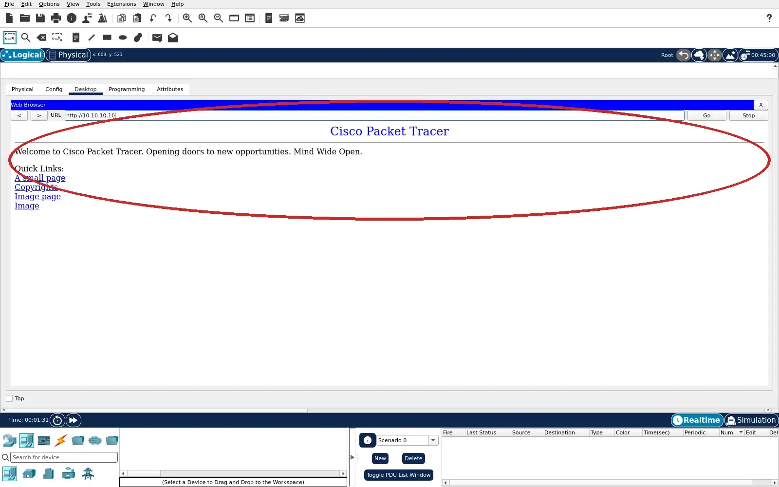
Step 8 · Cisco Packet Tracer; numbered callout added to a real capture. Enlarge screenshot (new tab) Step 9
- Do
- On PC2, open Desktop and Command Prompt. With ACL 110 restored, run ping 10.10.10.10. Read the source of each failure and the packet statistics. Do not describe this result as a browser or login rejection.
- You will see
- PC2 pings 10.10.10.10. Four replies from 10.30.30.1 say Destination host unreachable. No echo reply from 10.10.10.10 is shown. Statistics report Received = 0, Lost = 4.
- Why it matters
- The gateway rejects this unintended cross-VLAN path. The server is not merely slow: the router reports unreachable. This deny is paired with the earlier four-reply exposure. The operator HTTP exception remains a separate test.
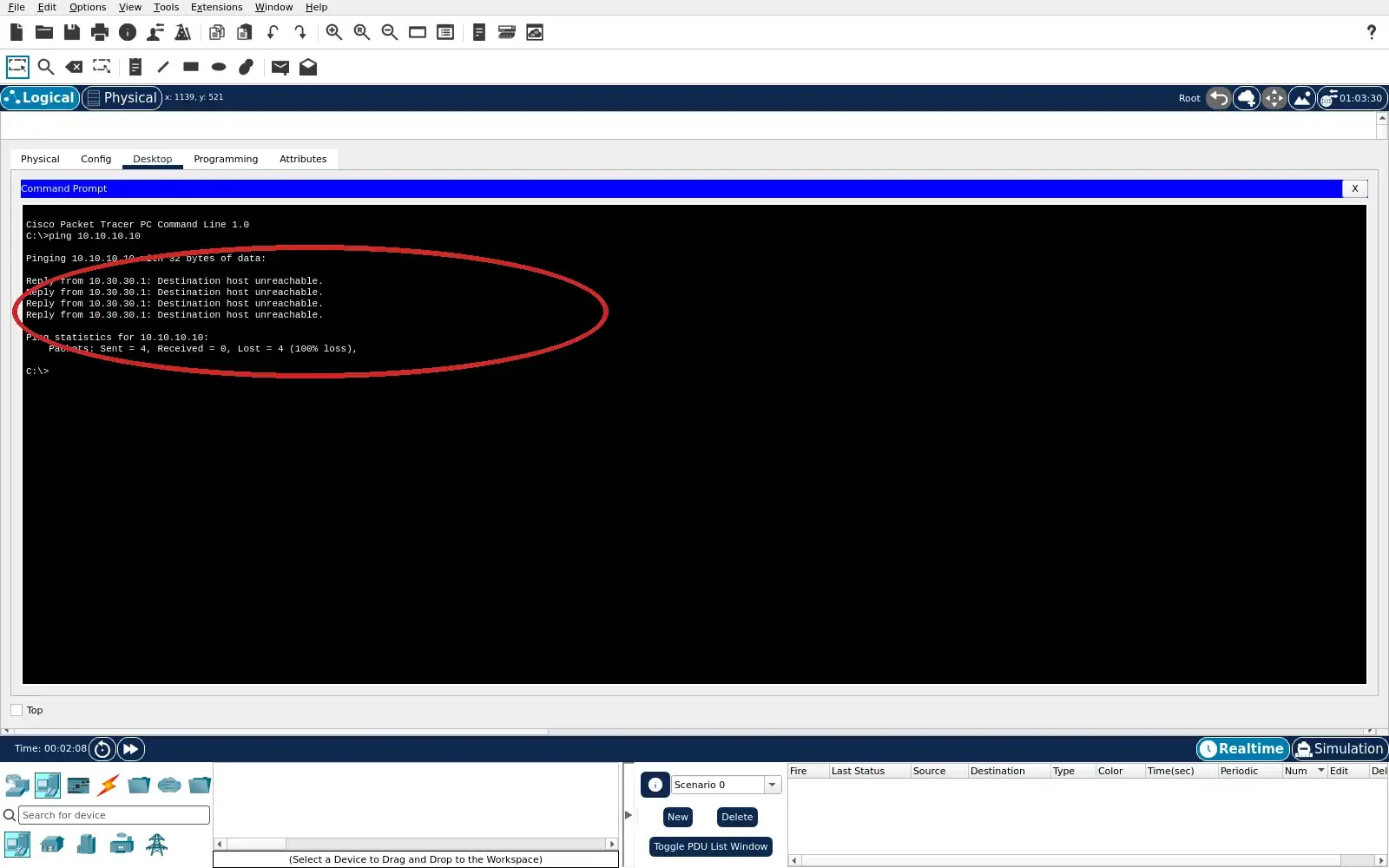
Step 9 · Cisco Packet Tracer; numbered callout added to a real capture. Enlarge screenshot (new tab) Step 10
- Do
- Return to VLAN-Gateway CLI tab after both traffic tests. Run show access-lists 110. Compare the HTTP permit and IoT-subnet deny counters. Leave the saved project with ACL 110 applied.
- You will see
- The extended IP access list is numbered 110. The operator TCP-to-www permit shows 6 match(es). The deny toward 10.10.10.0/24 shows 4 match(es). The router prompt reads VLAN-Gateway#.
- Why it matters
- The counters corroborate the two visible traffic outcomes. They are simulator counters, not production audit logs. This rule governs ingress toward VLAN 10 at the router. It does not block peers already sharing VLAN 10.
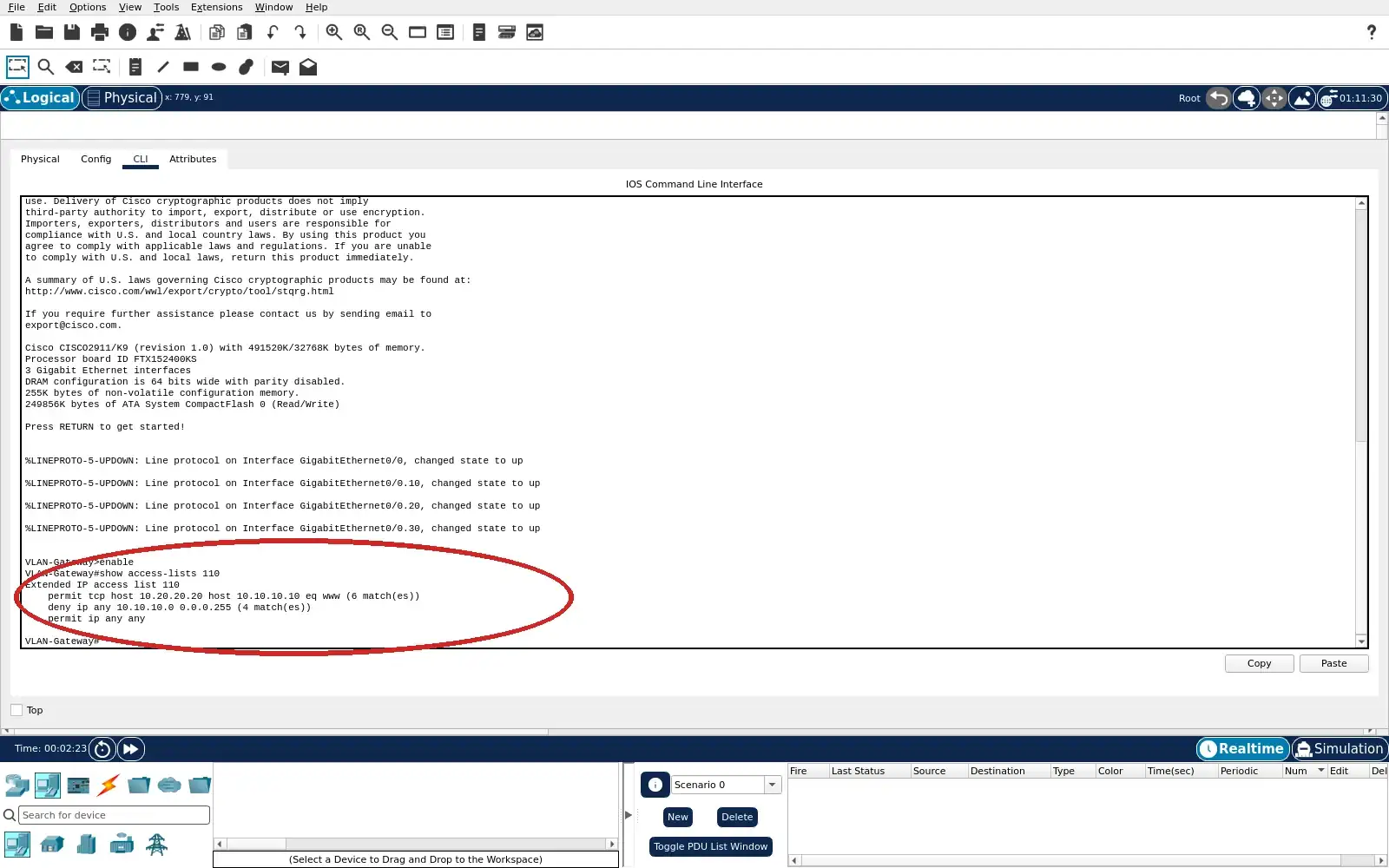
Step 10 · Cisco Packet Tracer; numbered callout added to a real capture. Enlarge screenshot (new tab)
Chapter checks
These questions refer to the chapter’s examples. Use the return links to review their answers.
What does network segmentation actually prove about an IoT deployment?
Return to the chapter’s knowledge checkWhy can placing all IoT devices in a single VLAN fail to stop a compromised camera from reaching sensors in the same VLAN?
Return to the chapter’s knowledge check