Industrial Device-State and Network Boundary
Inspect native PLC/HMI network state and compare plant and operator reachability before, during and after loss of the inter-switch conduit.

Packet Pete
Predict the reading, then compare it with the measurement.
Cisco Packet Tracer
Desktop labInspect native PLC/HMI network state and compare plant and operator reachability before, during and after loss of the inter-switch conduit.
Install the tool; build from the steps. No file yet.
Download the Packet Tracer fileSteps
Step 1
- Do
- Open lab.pkt in the Packet Tracer Logical workspace. Identify PLC0, HMI0, PC0 and Switch0 on the plant side. Find Switch1 and PC1 on the operator side. Follow the single inter-switch cable between the sides.
- You will see
- PLC0 and HMI0 attach to Switch0. PC0 attaches to the same plant switch. PC1 attaches to Switch1 across one inter-switch cable. The link markers are green in the saved healthy state.
- Why it matters
- The drawing names the two sides of the test. A link is a network conduit, not a PLC alarm rule. The plant PC gives a local comparison point. The operator PC tests what crosses the switch boundary.
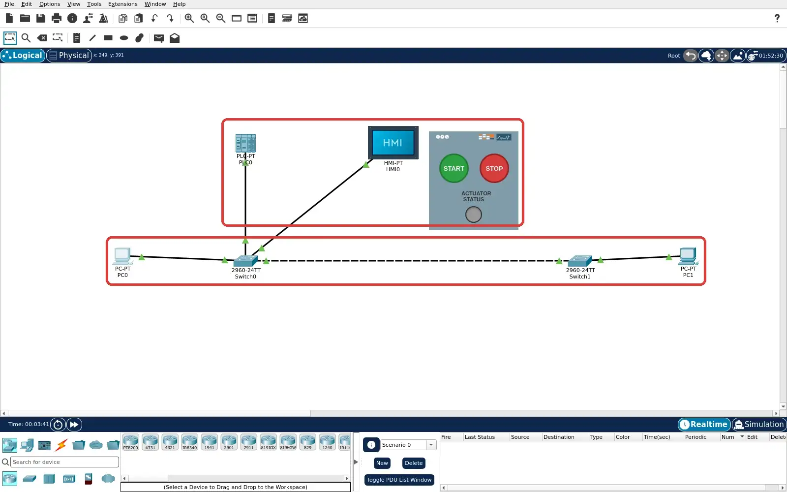
Step 1 · Cisco Packet Tracer; numbered callout added to a real capture. Enlarge screenshot (new tab) Step 2
- Do
- Open HMI0 and choose the Config tab. Select GigabitEthernet0 under Interface. Read its Port Status and IPv4 fields. Keep this native device window visible while noting the address.
- You will see
- GigabitEthernet0 Port Status is On. The IPv4 address field reads 192.168.50.12. The subnet mask reads 255.255.255.0. This view contains network settings rather than a threshold or alarm field.
- Why it matters
- The address gives both PCs a definite test target. It is a network identity for HMI0. A configured address does not establish sensor processing. The later pings test reachability only.
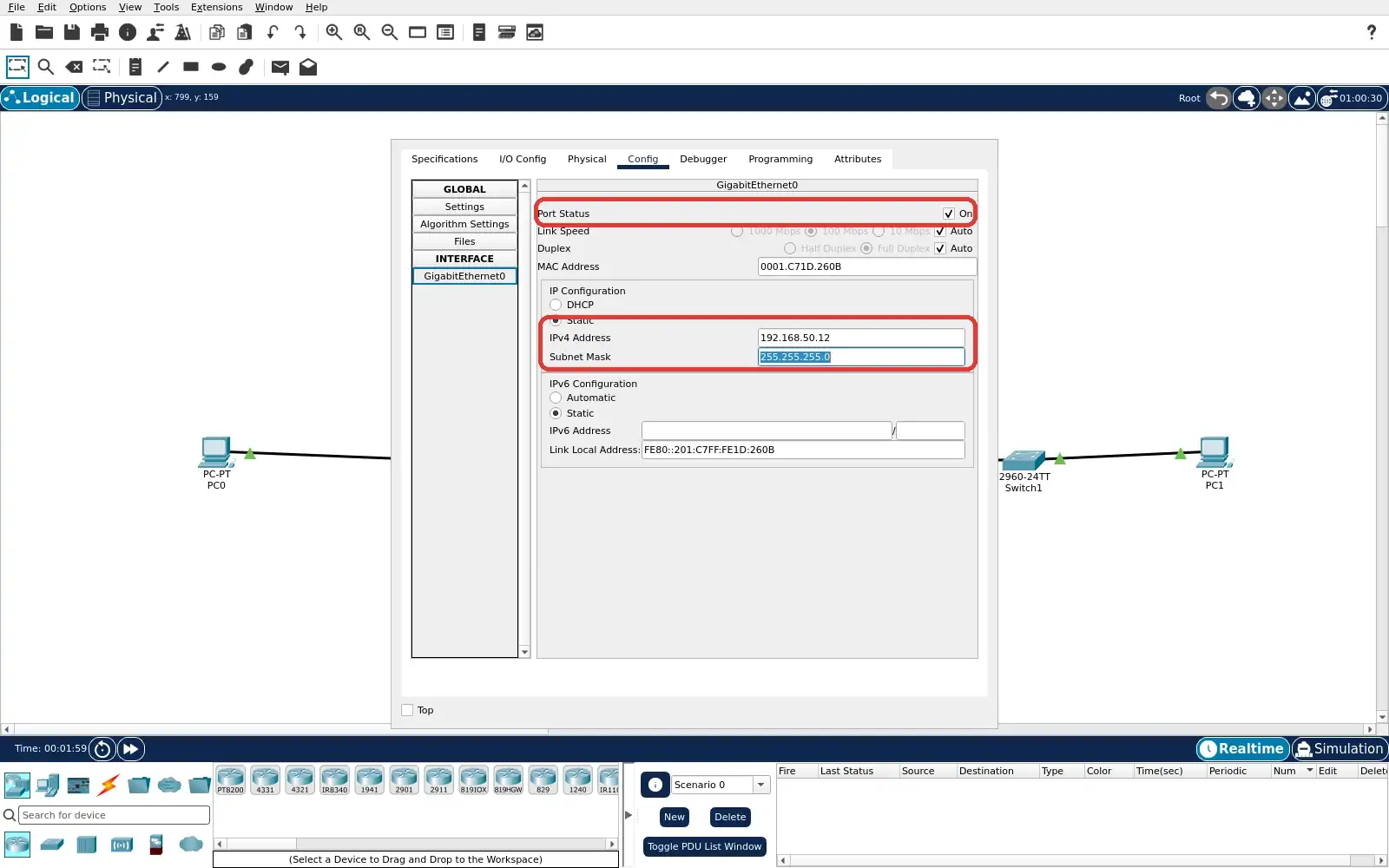
Step 2 · Cisco Packet Tracer; numbered callout added to a real capture. Enlarge screenshot (new tab) Step 3
- Do
- Open PC0 on the plant side. Choose Desktop and Command Prompt. Run ping 192.168.50.12. Read the four replies and the summary.
- You will see
- PC0 sends four echo requests to 192.168.50.12. All four receive replies from the HMI address. The summary reads Received = 4. The summary reads Lost = 0 (0% loss).
- Why it matters
- This is the healthy local network baseline. PC0 and HMI0 use the plant switch. The result will be repeated after the fault. ICMP reachability does not prove HMI alarm logic.
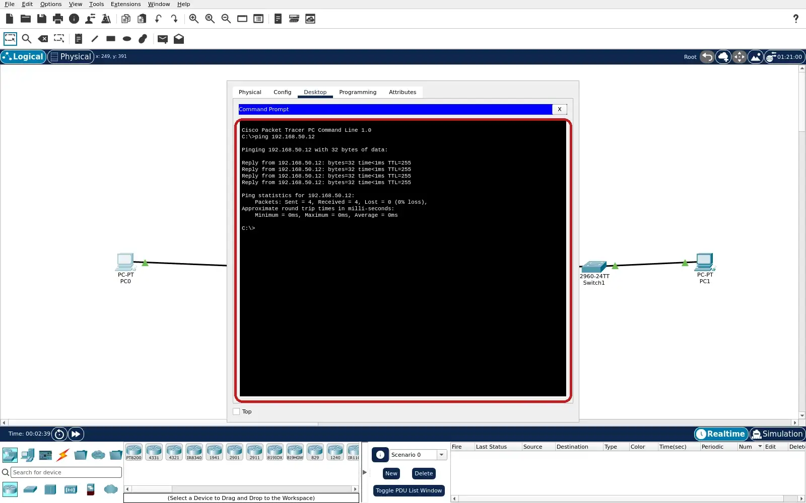
Step 3 · Cisco Packet Tracer; numbered callout added to a real capture. Enlarge screenshot (new tab) Step 4
- Do
- Open PC1 on the operator side. Choose Desktop and Command Prompt. Run ping 192.168.50.12 with the inter-switch cable connected. Read the four replies and the summary.
- You will see
- PC1 receives four replies from 192.168.50.12. The summary reads Received = 4. The summary reads Lost = 0 (0% loss). The healthy path crosses both switches.
- Why it matters
- This is the healthy operator network baseline. The operator side can reach the HMI address. The result is limited to IP connectivity. No live sensor or alarm value appears in this prompt.
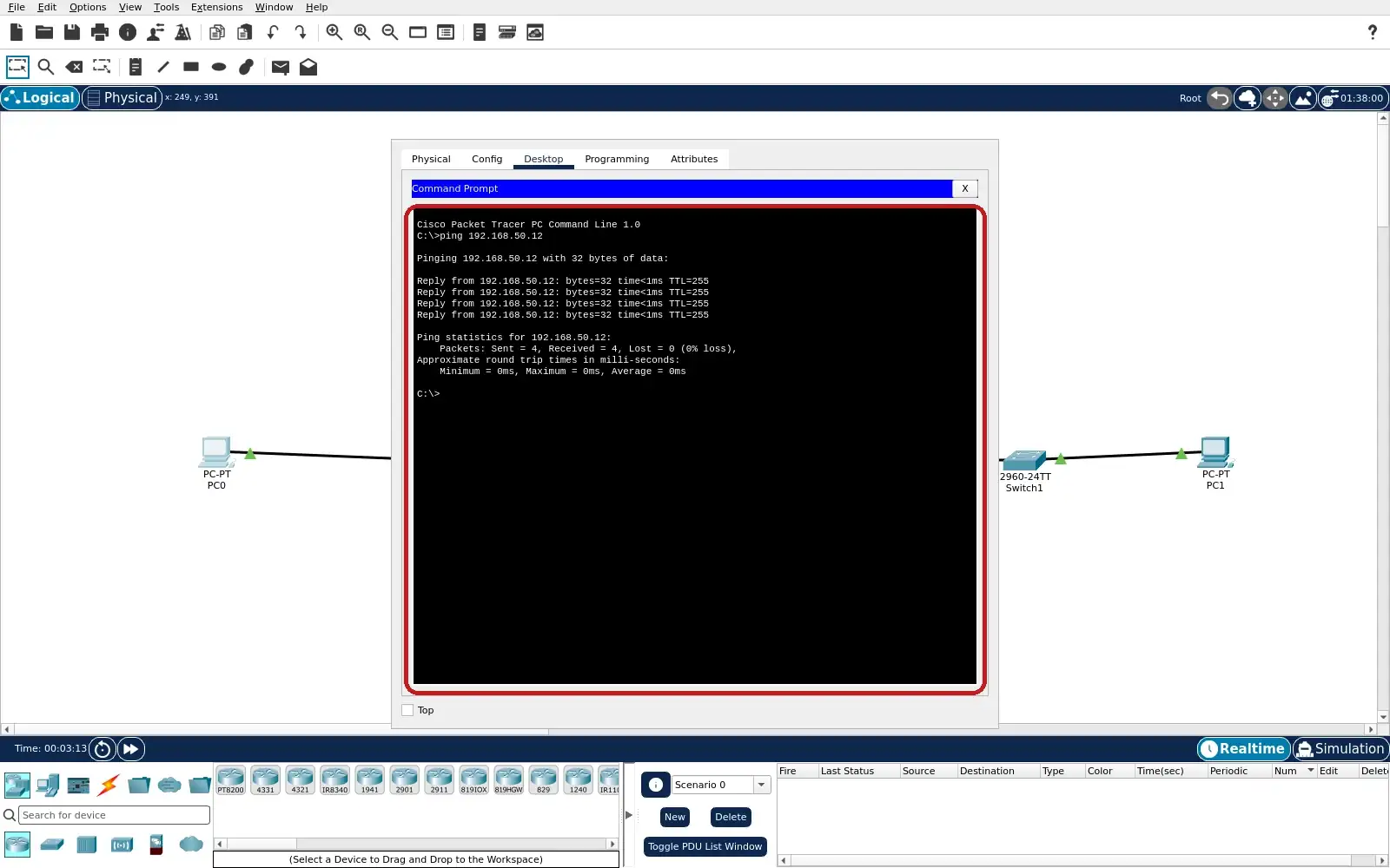
Step 4 · Cisco Packet Tracer; numbered callout added to a real capture. Enlarge screenshot (new tab) Step 5
- Do
- Return to the Logical workspace. Select the Delete tool on the top toolbar. Click only the dashed cable between Switch0 and Switch1. Check that PLC0, HMI0 and PC0 remain attached to Switch0.
- You will see
- The inter-switch cable is absent in this captured view. PLC0 and HMI0 remain wired to Switch0. PC0 also remains wired to Switch0. PC1 remains attached to Switch1.
- Why it matters
- The fault removes one network conduit. It does not remove the local HMI or plant PC wiring. The two PCs can now test different paths. Reopen the original lab.pkt to restore the cable after the exercise.
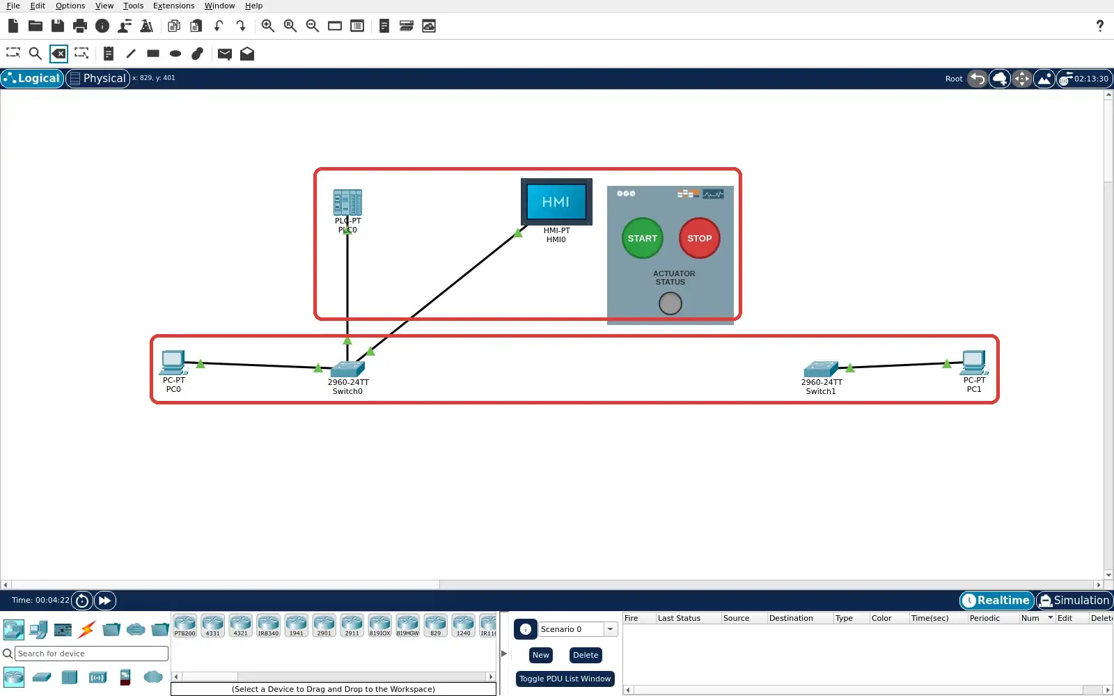
Step 5 · Cisco Packet Tracer; numbered callout added to a real capture. Enlarge screenshot (new tab) Step 6
- Do
- Keep the inter-switch cable removed. Bring PC0 Command Prompt back into view. Run ping 192.168.50.12 again. Read the new summary below the earlier baseline.
- You will see
- The repeated PC0 ping receives four HMI replies. The new summary reads Received = 4. The new summary reads Lost = 0 (0% loss). The target remains 192.168.50.12.
- Why it matters
- The local plant network path remains reachable. Switch0 still connects PC0 and HMI0. This is reachability continuity, not a safety proof. The earlier operator baseline provides the comparison.
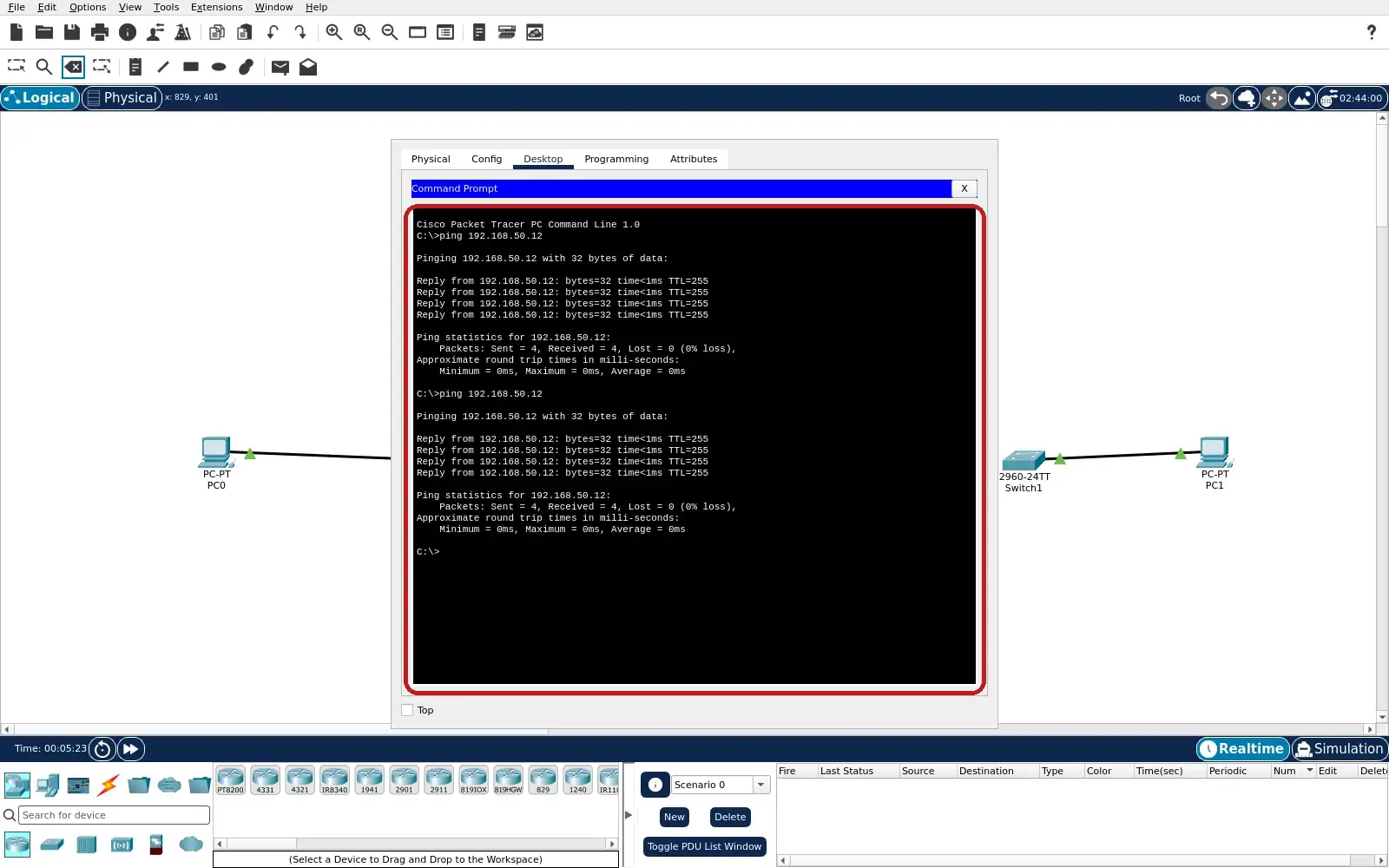
Step 6 · Cisco Packet Tracer; numbered callout added to a real capture. Enlarge screenshot (new tab) Step 7
- Do
- Keep the inter-switch cable removed. Bring PC1 Command Prompt back into view. Run ping 192.168.50.12 again. Wait for all four requests and read the final summary.
- You will see
- The second PC1 ping reports four Request timed out lines. Its summary reads Received = 0. Its summary reads Lost = 4 (100% loss). The prior healthy four-reply result remains visible above.
- Why it matters
- The operator-side network path is interrupted. The local result in the previous step still succeeds. A timeout is absence of reachability evidence. It is not evidence of a PLC alarm, stale HMI value or historian record.
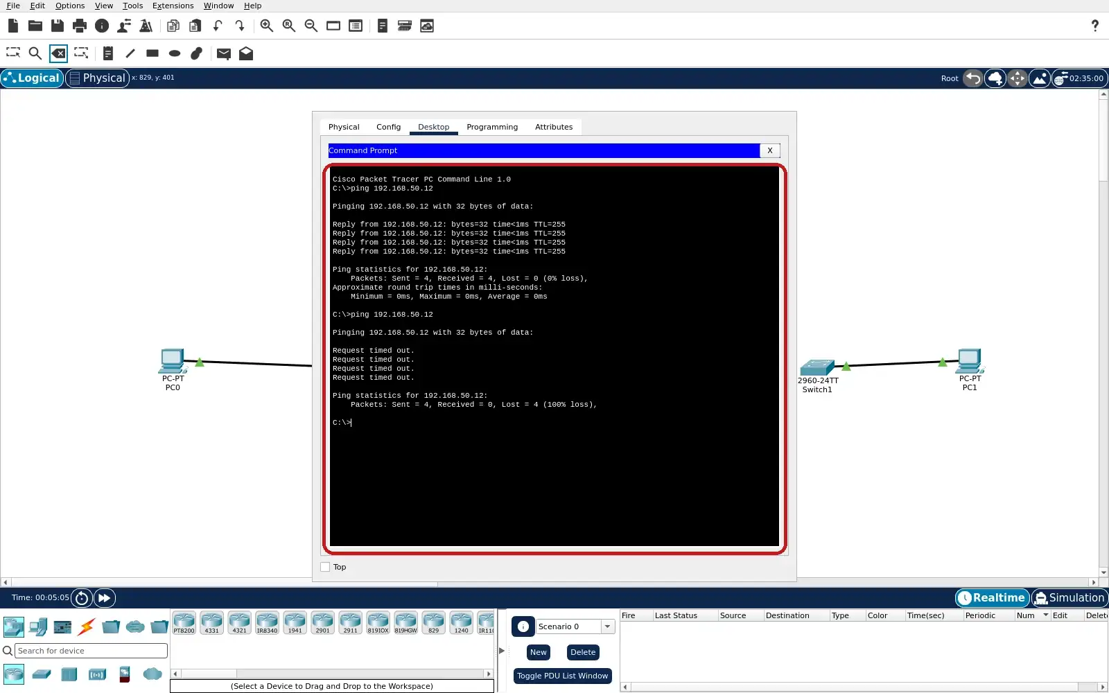
Step 7 · Cisco Packet Tracer; numbered callout added to a real capture. Enlarge screenshot (new tab) Step 8
- Do
- Close the faulted run without saving it over lab.pkt. Reopen the supplied healthy lab.pkt in Packet Tracer. On PC1, open Desktop Command Prompt. Run ping 192.168.50.12 and read the summary.
- You will see
- The PC1 Command Prompt again targets 192.168.50.12. PC1 receives four replies from 192.168.50.12. The summary reads Received = 4. The summary reads Lost = 0 (0% loss).
- Why it matters
- The saved project restores the healthy conduit. The repeated operator ping verifies reachability after reopen. This is a simulator network recovery observation. No sensor-to-PLC-to-HMI alarm behavior is claimed.
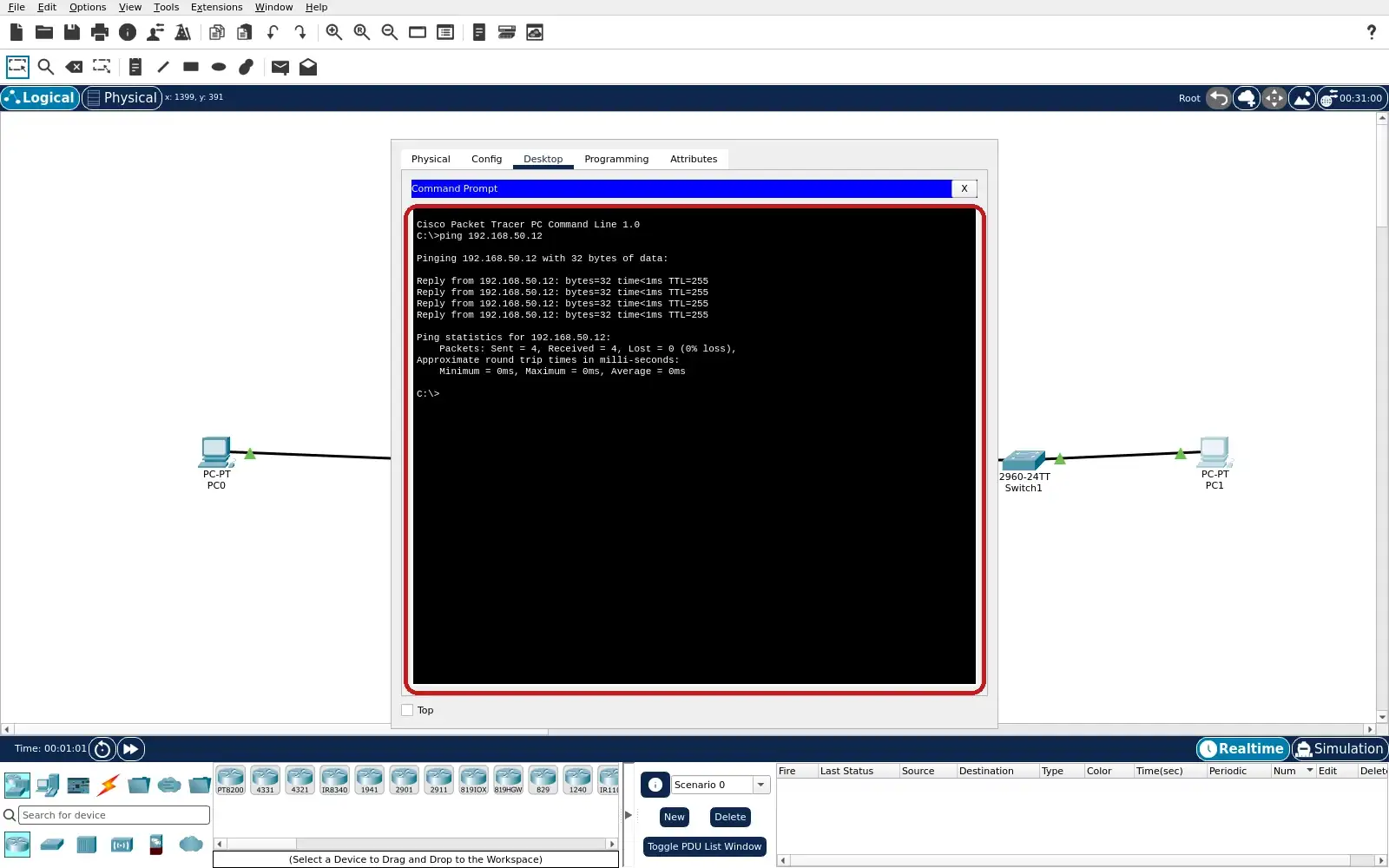
Step 8 · Cisco Packet Tracer; numbered callout added to a real capture. Enlarge screenshot (new tab)
Chapter checks
These questions refer to the chapter’s examples. Use the return links to review their answers.
An operator PC loses contact with an HMI after the inter-switch link is removed, while a plant PC still receives four HMI ping replies. What has the test established?
Return to the chapter’s knowledge checkBefore claiming that a Packet Tracer PLC threshold raised an HMI alarm, which evidence is still required?
Return to the chapter’s knowledge check
Return to Manufacturing IoT: OT Integration Boundaries · Browse Labs