Op-amp sensor gain and saturation
Study Op-Amp Sensor Front-End Contracts from the Electronics module guide by comparing non-inverting gain and supply-rail saturation.
Predict output peak from feedback ratio before inspecting both scopes.
Predict the reading, then compare it with the measurement.
Falstad CircuitJS
Third party ToolStudy Op-Amp Sensor Front-End Contracts from the Electronics module guide by comparing non-inverting gain and supply-rail saturation.
Open the prepared circuit.
Open this circuit in Falstad (new tab)Steps
Step 1
- Do
- Open the gain-two op-amp circuit on the Falstad canvas and inspect the input and output scopes.
- You will see
- Input: synthetic fixed-seed set, seed 15. Input source: 100 Hz sine, 0.5 V peak. Input scope: Max=500 mV. Output scope: Max=999.98 mV. Feedback resistor: 10 kΩ. Ground resistor: 10 kΩ.
- Why it matters
- The non-inverting feedback ratio 1 + 10 kΩ / 10 kΩ predicts gain two in the unsaturated range.
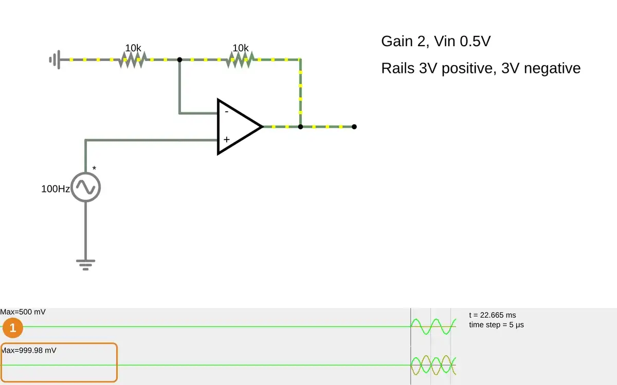
Step 1 · Falstad CircuitJS; numbered callout added to a real capture. Enlarge screenshot (new tab) Step 2
- Do
- Point to the output scope on the canvas and compare its peak with the input scope while reading the rail labels.
- You will see
- Input scope: Max=500 mV. Output scope: Max=999.98 mV. Positive rail: 3 V. Negative rail: -3 V. The output peak is below either rail.
- Why it matters
- This real waveform verifies linear gain at the starting input; the rail values set a ceiling for later steps.
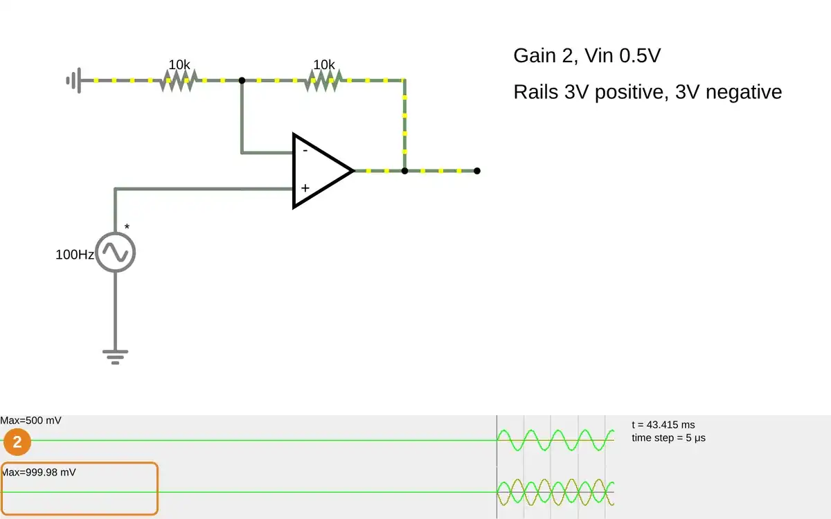
Step 2 · Falstad CircuitJS; numbered callout added to a real capture. Enlarge screenshot (new tab) Step 3
- Do
- Open the gain-five circuit on the canvas and inspect both scopes after feedback rises to 40 kΩ.
- You will see
- Input source: 100 Hz, 0.5 V peak. Ground resistor: 10 kΩ. Feedback resistor: 40 kΩ. Input scope: Max=500 mV. Output scope: Max=2.5 V.
- Why it matters
- The output grows to five times the input without clipping because 2.5 V remains within the modeled 3 V rail.
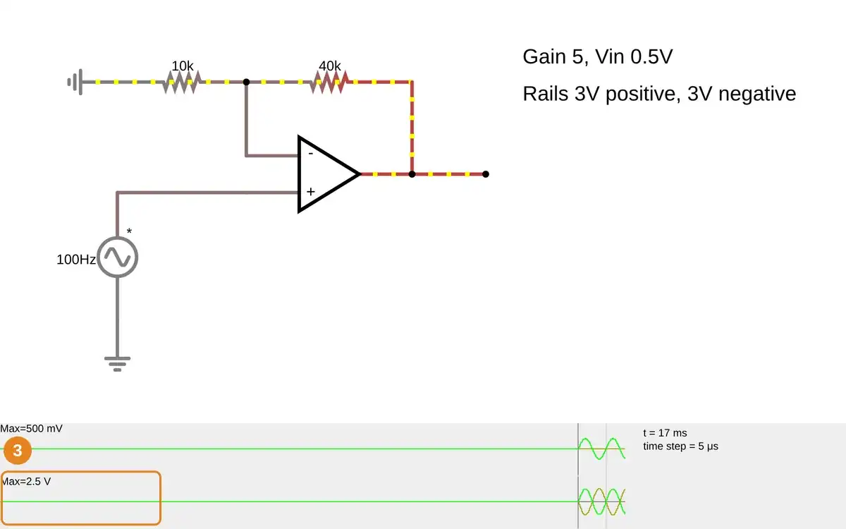
Step 3 · Falstad CircuitJS; numbered callout added to a real capture. Enlarge screenshot (new tab) Step 4
- Do
- Open the 1 V input, gain-five circuit on the canvas and watch the output scope flatten near the rails.
- You will see
- Input scope: Max=1 V. Linear gain-five target: 5 V peak. Output scope: Max=3.002 V. Modeled rails: +3 V and -3 V. The output trace has flat plateaus.
- Why it matters
- The model saturates at its rails; the linear target cannot be reached with this supply.
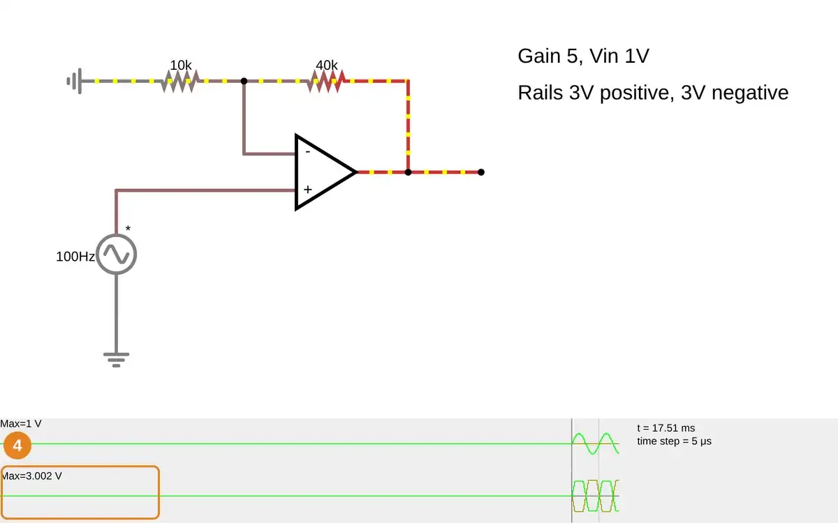
Step 4 · Falstad CircuitJS; numbered callout added to a real capture. Enlarge screenshot (new tab) Step 5
- Do
- Open the 1 V input, gain-two circuit on the canvas and compare both scopes after reducing feedback to 10 kΩ.
- You will see
- Input scope: Max=1 V. Feedback resistor: 10 kΩ. Ground resistor: 10 kΩ. Output scope: Max=2 V. The output trace is sinusoidal again.
- Why it matters
- Reducing gain returns the 1 V input to an output range below the rails.
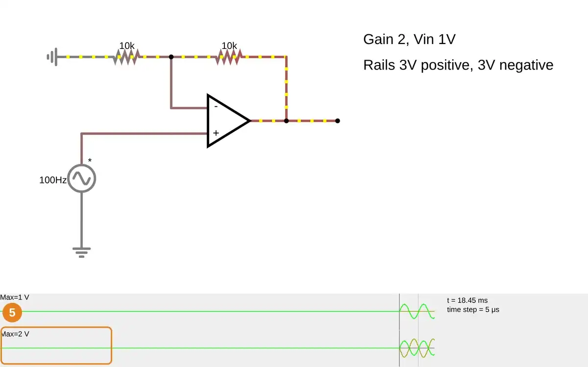
Step 5 · Falstad CircuitJS; numbered callout added to a real capture. Enlarge screenshot (new tab) Step 6
- Do
- Restore the initial circuit on the canvas and record the input and output scope readouts as the comparison baseline.
- You will see
- Input scope: Max=500 mV. Output scope: Max=999.98 mV. Feedback: 10 kΩ over 10 kΩ. Rails: +3 V and -3 V. The full circuit and both scopes remain visible.
- Why it matters
- The simulated gain and clipping boundary are reproducible in this model; they do not establish device offset, noise, bandwidth, or real output swing.
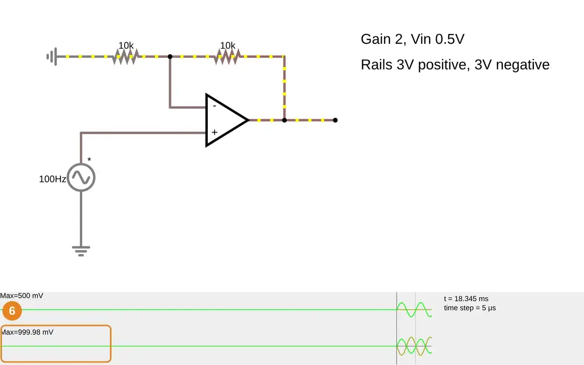
Step 6 · Falstad CircuitJS; numbered callout added to a real capture. Enlarge screenshot (new tab)
Chapter checks
These questions refer to the chapter’s examples. Use the return links to review their answers.
With negative feedback and an unsaturated output, what do the two op-amp golden rules say?
Return to the chapter’s knowledge checkAn op-amp circuit is powered from a single rail. Which check must precede a claim that its full sensor range is readable?
Return to the chapter’s knowledge check