Measure inductive drive current and flyback
Follow the actuator guide's driver-current and flyback questions through a transistor-switched inductive-load model.

Follow both the current through the inductive load and the voltage across its switch at turn-off.
Predict the reading, then compare it with the measurement.
Falstad CircuitJS
Third party ToolFollow the actuator guide's driver-current and flyback questions through a transistor-switched inductive-load model.
Open the prepared circuit.
Open this circuit in Falstad (new tab)Steps
Step 1
- Do
- Open the protected circuit canvas and inspect the 5 V supply and coil.
- You will see
- Supply source: 5 V DC. Inductive load model: 50 mH coil and 20 Ω series resistor. Drive source: 100 Hz square, 50% duty. All component values are synthetic teaching inputs, seed 0.
- Why it matters
- The model exposes the load path and switch before comparing protection.
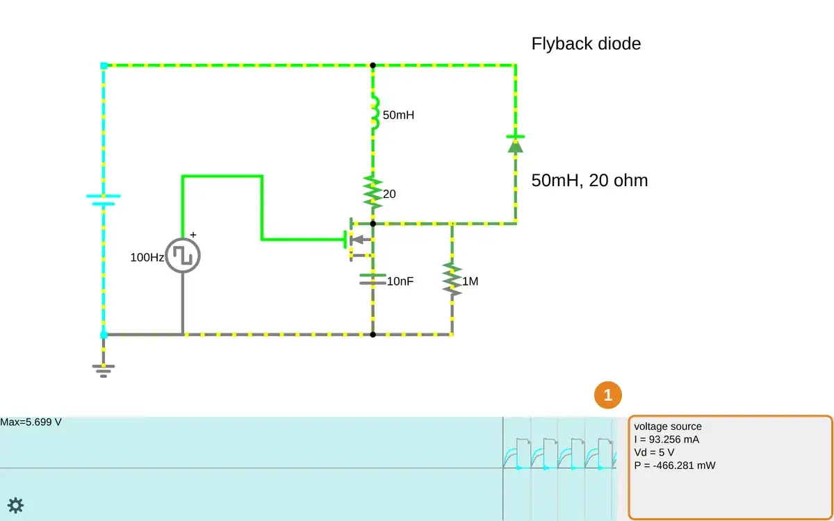
Step 1 · Falstad CircuitJS; numbered callout added to a real capture. Enlarge screenshot (new tab) Step 2
- Do
- Point at the inductor on the canvas and read its drive current.
- You will see
- With diode: sampled coil-current peak=115.680 mA (scope Max about 115.689 mA). Near the end of ON: coil=115.676 mA; MOSFET current=115.674 mA; Vds=2.674 V. Effective MOSFET on-resistance then is 2.674 V / 0.115674 A = 23.11 Ω. With the 20 Ω resistor, Rtotal≈43.11 Ω and 50 mH / Rtotal≈1.16 ms near the peak. The 5 ms ON interval begins near 0.06 mA left after the previous OFF interval. Ideal 5 V / 20 Ω = 250 mA assumes a switch with zero voltage drop. Falstad model steady current≈115.83 mA; its nonlinear 5 ms rise predicts≈115.69 mA. These are circuit-model values, not a motor stall rating.
- Why it matters
- The MOSFET drops about 2.67 V at the peak, leaving about 2.33 V across the 20 Ω resistor. Its resistance changes with current; the 115.7 mA peak agrees with the model rise, while the driver carries that current during ON.
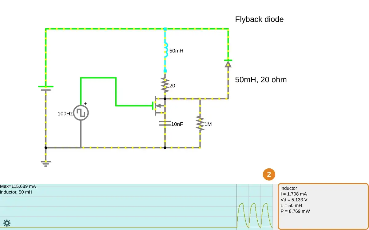
Step 2 · Falstad CircuitJS; numbered callout added to a real capture. Enlarge screenshot (new tab) Step 3
- Do
- Point at the diode on the circuit canvas and inspect the voltage scope.
- You will see
- With diode: sampled switch-node peak=5.697 V. Live scope read Max=5.699 V in the protected run. The diode conducts after switch-off as coil current decays. The switch node stays close to the 5 V rail plus diode drop.
- Why it matters
- A flyback path limits voltage while stored magnetic energy dissipates.
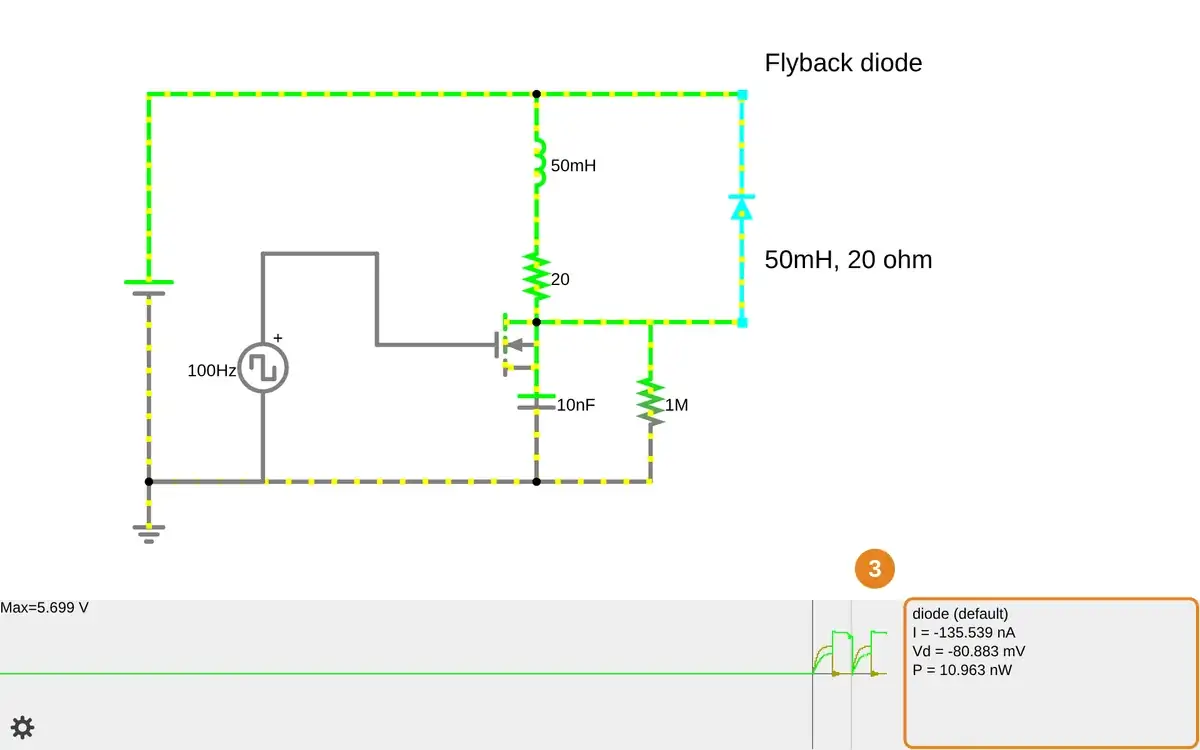
Step 3 · Falstad CircuitJS; numbered callout added to a real capture. Enlarge screenshot (new tab) Step 4
- Do
- Open the unprotected circuit canvas and inspect the switch voltage scope.
- You will see
- Without diode: sampled switch-node peak=95.860 V. The live scope showed a 258.669 V maximum in one run. The 10 nF parasitic capacitor and 1 MΩ leak path keep this idealized model finite. The turn-off ring includes negative current samples down to -105.788 mA.
- Why it matters
- Removing the diode lets coil energy charge the switch-node capacitance and ring.
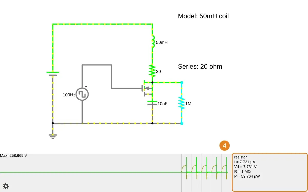
Step 4 · Falstad CircuitJS; numbered callout added to a real capture. Enlarge screenshot (new tab) Step 5
- Do
- Return to the protected circuit canvas and compare the switch readout.
- You will see
- With diode: scope maximum was 5.699 V. Without diode: scope maximum was 258.669 V in the comparison run. The protected coil-current peak was 115.680 mA. The 5 V, 50 mH, 20 Ω values are model choices, not hardware limits.
- Why it matters
- The voltage comparison supports a flyback path without claiming a hardware safety rating.
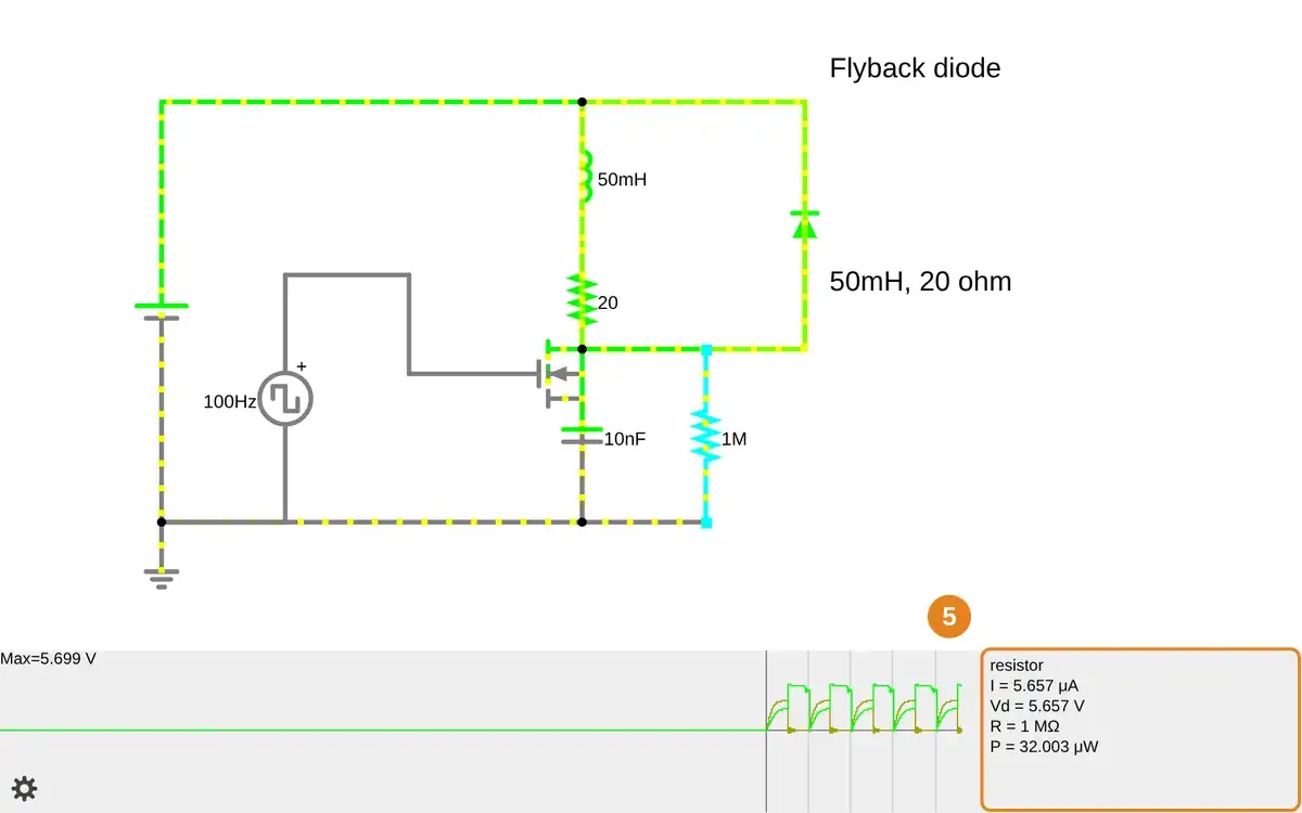
Step 5 · Falstad CircuitJS; numbered callout added to a real capture. Enlarge screenshot (new tab)
Chapter checks
These questions refer to the chapter’s examples. Use the return links to review their answers.
A standard hobby servo receives a 1.5ms pulse at 50 Hz. What position will the servo move to?
Return to the chapter’s knowledge checkA high-torque servo has a stall current of 2.5A. If you are building a 3-servo robotic arm, what minimum power supply current rating do you need?
Return to the chapter’s knowledge check