Sensors & Measurement · Study deck
Sensor Circuits: Dividers and Filtering
A motor can make a sound sensor value jump even when the sensor is healthy.
Physics Phoebe is your guide for this deck.
After studying this chapter
Learning objectives
You will be able to:
- Design Voltage Dividers: Calculate resistor values for interfacing resistive sensors with ADCs
- Build RC Filters: Create low-pass filters to remove noise from sensor signals
- Implement Transistor Switches: Use transistors to control high-power loads from GPIO pins
- Calculate LED Resistors: Properly size current-limiting resistors for LED indicators
Major section
Start With the Measurement Story
This runway does not prove every sensor or circuit is accurate.
- The sensor may be healthy while its wiring, supply, filter, or input circuit changes the value.
- A microcontroller means the small computer that reads inputs and controls a device.
- A sensor signal usually reaches the microcontroller through a circuit before it becomes data.
Major section
Voltage Divider Circuit
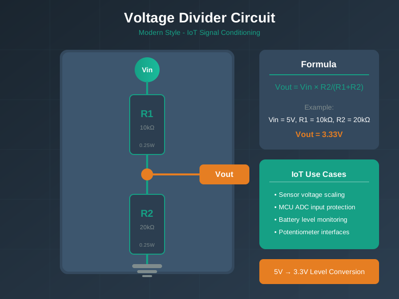
Theory:: A voltage divider is the most fundamental circuit for interfacing resistive sensors (LDR, thermistors, potentiometers) with microcontrollers.
- It converts resistance changes into voltage changes that ADCs can measure.
- With R1 = 10 kΩ and R2 = 20 kΩ, the shown relation gives 5 V × 20/(10 + 20) = 3.33 V.
Major section
Learning Points
Variable Resistance: Changing R1 or R2 changes V_out proportionally.
- Real-World Application:: These resistive sensors (LDR, thermistor, flex sensor, potentiometer) commonly use a voltage divider to interface with microcontroller ADCs.
- The circuit makes the changing LDR resistance and the fixed resistor part of one measurable ratio.
Major section
Putting Numbers to It
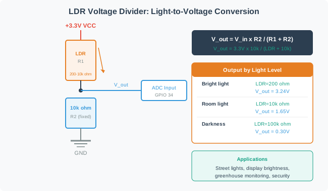
LDR Voltage Divider Design: An LDR varies from 200Ω (bright sunlight) to 10kΩ (darkness).
- With the same fixed value, swapping the sensor between top and bottom reverses the direction but preserves the swing magnitude.
- A fixed value near the geometric mean of the sensor range is a useful starting choice: $\sqrt{200 \times 10{,}000} \approx 1{,}414\Omega$; 1.5 kΩ is a closer standard value than 1 kΩ.
- The worked Option 2 still uses 1 kΩ.
Deck summary
Key takeaways
This runway does not prove every sensor or circuit is accurate.
- Theory:: A voltage divider is the most fundamental circuit for interfacing resistive sensors (LDR, thermistors, potentiometers) with microcontrollers.
- Variable Resistance: Changing R1 or R2 changes V_out proportionally.
- LDR Voltage Divider Design: An LDR varies from 200Ω (bright sunlight) to 10kΩ (darkness).
Retrieval practice
Recall check 1 of 3

Physics Phoebe says: answer from memory, then check your reasoning.
Q1A thermistor (10kohm at 25C) is placed as R1 in a voltage divider with a 10kohm fixed resistor R2 and 3.3V supply. As temperature increases and thermistor resistance drops to 5kohm, what happens to the output voltage at the junction?
Show answer
Answer: B Correct!
Retrieval practice
Recall check 2 of 3

Physics Phoebe says: answer from memory, then check your reasoning.
Q2Your I2C bus has 4 sensors with 50cm cable runs, and communication becomes unreliable at 400kHz but works at 100kHz. The internal MCU pull-ups are 45kohm. What is the most effective fix?
Show answer
Answer: B Correct!
Retrieval practice
Recall check 3 of 3

Physics Phoebe says: answer from memory, then check your reasoning.
Q3You need to filter 60Hz mains noise from a temperature sensor that updates every 2 seconds. What RC filter cutoff frequency should you choose?
Show answer
Answer: B Correct: a 1 Hz first-order RC attenuates 60 Hz by about 35.6 dB. If readings are sampled only every 2 seconds, add adequate anti-alias filtering or sample faster and filter before decimating.
Print reference
Answers
Answer key.
- B · Correct!
- B · Correct!
- B · Correct: a 1 Hz first-order RC attenuates 60 Hz by about 35.6 dB. If readings are sampled only every 2 seconds, add adequate anti-alias filtering or sample faster and filter before decimating.