Prototyping · Study deck

Hardware Prototyping: First-Build Experiments

An LED and resistor can test a new board without hiding faults.

Voltage Vera is your guide for this deck.

gettingstarted
iotclass.org

After studying this chapter

Learning objectives

You will be able to:

  • Test first build as experiment with a concrete scenario and pass criteria.
  • Evaluate first measurement with range, error, power, and interface evidence.
  • Prepare a first hardware prototyping bench with safe power, measurement, and wiring habits.
  • Bring up a development board using a known-good firmware test before adding external components.
iotclass.org

Major section

Start With the Story

The first bench build often fails for ordinary reasons: a jumper is in the wrong rail, a sensor has no ground reference, a board package is stale, or the supply current limit is set too low.

  • A novice sees a broken project.
  • A good prototyper sees a sequence to make the failure visible without guessing.
  • When the bench record is clear enough for another person to repeat, the prototype has become evidence instead of a private memory.
iotclass.org

Major section

First Build as Experiment
The pin note maps tutorial D2 to board GP2 and firmware GPIO2, but the real pinout and wire still need checking.

  • That staged record makes a failed rail or wrong pin easier to isolate.
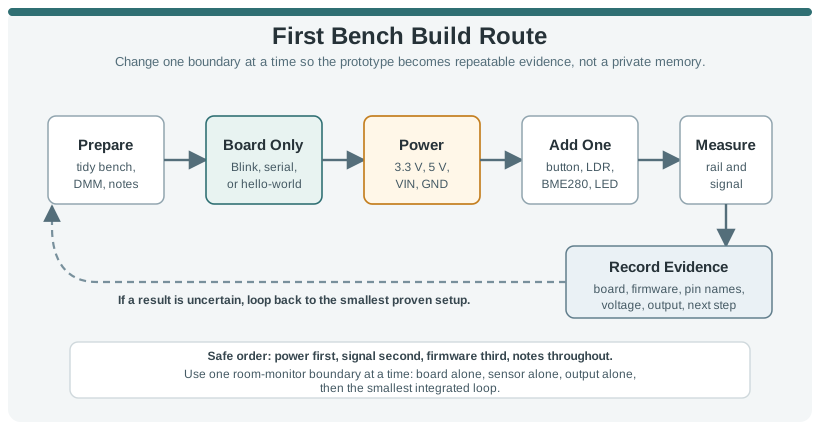
  • The reliable path is board first, power second, one external part third.
  • After the baseline works, add one boundary.

Why it matters

In the An Arduino Uno makes the board-only baseline visible: USB, power input, socketed microcontroller, reset control, and labelled headers can all be checked before a sensor is added diagram, inspect the power and USB entries before the labelled headers, because those are the boundaries that must work before a sensor can be blamed.

A first bench build should stay inside a controlled route: prepare the bench, prove the board alone, check power, add one boundary, measure what changed, and record the evidence before adding complexity.
iotclass.org

Major section

First Build as Experiment (continued)

A room-monitor demo, button-and-LED test, or sensor-readout sketch should never start with every wire, library, and enclosure choice changing at once.

  • For example, a first room-monitor build with an Arduino Uno R4 WiFi, Raspberry Pi Pico W, ESP32 DevKit, or Adafruit Feather should begin with the board by itself.
  • If that baseline fails, the next useful action is not wiring a BME280, relay board, or OLED display.
  • The board-only step is easier to understand when the physical interfaces are visible.
  • USB can supply both power and the programming path, while the alternate power input changes the electrical assumptions.
iotclass.org

Major section

First Build as Experiment (continued)

In Figure: An Arduino Uno makes the board-only baseline visible, inspect the power and USB entries before the labelled headers, because those are the boundaries that must work before a sensor can be blamed.

  • Proving this unchanged board state keeps the first external component from being mixed into cable, target-selection, or upload faults.
  • A beginner temperature indicator might add only a BME280 on I2C, measure the 3.3 V rail before and after wiring, scan or log the detected address, and print one raw reading.
  • When the final loop fails, you know which boundary changed last.
An Arduino Uno makes the board-only baseline visible: USB, power input, socketed microcontroller, reset control, and labelled headers can all be checked before a sensor is added.
iotclass.org

Major section

Bring Up One Boundary at a Time

The coloured conductor helps a builder follow a path by eye, but colour does not prove electrical continuity or destination.

  • The discipline is in the sequence, not the price of the tools.
  • A practical first-bench log should be boring and specific.
  • A digital multimeter can prove polarity, voltage, continuity, and a missing ground.

Why it matters

Measuring both places prevents that mistake from becoming a library problem.

iotclass.org

Major section

Bring Up One Boundary at a Time (continued)

A USB-powered Pico W or ESP32 board may look fine at the USB connector while a loose jumper leaves the sensor rail unpowered.

  • The jumper-wire photo in Figure: Male-to-male jumper wires bridge development-board headers to breadboard shows the removable connections used in an early bench build.
  • The photograph shows a connection style and its visible parts; the board rail and row measurements establish whether this particular wiring works.
  • A serial monitor can prove firmware identity and show whether the loop is running.
  • A current-limited bench supply can keep a wiring mistake from damaging a regulator.
Male-to-male jumper wires bridge development-board headers to breadboard rows. Their colors help trace a circuit, but color is not an electrical guarantee: follow each end to its numbered row and test suspect leads for continuity before blaming firmware. Photo: Edwiyanto, CC BY-SA 4.0
iotclass.org

Major section

Bring Up One Boundary at a Time (continued)

Measuring both places prevents that mistake from becoming a library problem.

  • A Saleae Logic, Bus Pirate, or sigrok/PulseView capture can show whether I2C SCL and SDA are moving and whether the sensor NACKs its address.
  • Beginners do not need all of these at once, but they should understand what each tool can and cannot see.
  • The rotary selector chooses continuity, voltage, or current, and the LCD reports the result for the connected probes.
A digital multimeter turns a wiring guess into evidence. The rotary selector chooses what the probes measure; continuity is checked with power removed, voltage is measured across two points, and current requires deliberately opening the circuit and placing the meter in series. Photo: oomlout, CC BY-SA 2.0
iotclass.org

Major section

First Failures Hit Boundaries

Many early faults are caused by two names for the same physical point not being checked against each other.

  • A tutorial may say D2, a board silkscreen may say GP2, a microcontroller data sheet may name the package pin differently, and a framework may expose the pin as GPIO2 or a board-specific constant.
  • Signal level and current limits are the other hidden boundaries.
  • A 5 V sensor output can overdrive a 3.3 V GPIO unless a divider, level shifter, or compatible module is used.
  • A first-bench workflow catches those limits before the circuit is enclosed, soldered, or copied into a more complex prototype.
iotclass.org

Major section

Set Up the Bench

Your first bench does not need to be elaborate.

  • It needs to be repeatable and measurable.
  • Clean workspace: Enough room to keep the board, breadboard, cable, and notes visible without loose metal parts touching the circuit.
  • Known power source: A powered USB port, bench supply, or battery input with the expected voltage and current limit understood.
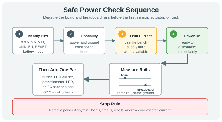
Safe first power proceeds from documented pins and power-off checks to measured rails and a strict stop rule.
iotclass.org

Major section

Set Up the Bench (continued)

Heating, smell, repeated resets, or unexpected current invokes the stop rule: remove power before touching wiring.

  • Wiring materials: Breadboard, jumper wires, resistors, and short leads that can be traced visually.
  • Documentation habit: A small record of board type, firmware file, wiring changes, measurements, and observed behavior.
  • This makes electrical safety the entry condition for each incremental experiment.
iotclass.org

Deck summary

Key takeaways

The first bench build often fails for ordinary reasons: a jumper is in the wrong rail, a sensor has no ground reference, a board package is stale, or the supply current limit is set too low.

  • The pin note maps tutorial D2 to board GP2 and firmware GPIO2, but the real pinout and wire still need checking.
  • A room-monitor demo, button-and-LED test, or sensor-readout sketch should never start with every wire, library, and enclosure choice changing at once.
  • The coloured conductor helps a builder follow a path by eye, but colour does not prove electrical continuity or destination.
iotclass.org

Retrieval practice

Recall check 1 of 6

Voltage Vera says: answer from memory, then check your reasoning.

Q1Another engineer must rebuild the first prototype. Which record should they receive?

AProvide only final source code and let the next engineer infer wiring, power settings and test order.
BWiring photo, parts, power settings, firmware version, measurements, and each step result.
CProvide a picture of the working board as the sole record of firmware and measured results.
DProvide a parts list without wiring photos, power settings or the result of each build step.
Show answer

Answer: B The record lets another builder repeat both setup and evidence.

iotclass.org

Retrieval practice

Recall check 2 of 6

Voltage Vera says: answer from memory, then check your reasoning.

Q2A first sensor reading looks plausible. What makes that measurement useful for a design decision?

ASave the displayed value alone, without its expected range, power state or interface setup.
BTreat one plausible measurement as proof of product readiness, with no error or setup record.
CRecord expected range, measured value and error, power state, interface setting, and setup.
DChange wiring until the value looks right, without preserving measured error or power state.
Show answer

Answer: C The measurement needs context and repeatability before it supports a choice.

iotclass.org

Retrieval practice

Recall check 3 of 6

Voltage Vera says: answer from memory, then check your reasoning.

Q3A new breadboard stops booting after several parts are added. Which debug move best finds the cause?

AReplace all parts at once, then assume whichever booted last was responsible for the fault when the fault recurs.
BEdit application code before checking whether supply or ground failed after the new part.
CKeep adding parts until boot succeeds and skip returning to the last working circuit.
DReturn to the last working state, check supply and ground, then add one part while measuring each change.
Show answer

Answer: D Staged bring-up preserves a known baseline for fault isolation.

iotclass.org

Retrieval practice

Recall check 4 of 6

Voltage Vera says: answer from memory, then check your reasoning.

Q4Using this chapter's own worked numbers (3.3 V rail, red LED with Vf = 2.0 V, target current I = 10 mA), what series resistor value does the LED-resistor formula R = (Vs - Vf) / I give?

A330 ohms, from 3.3 V divided directly by 0.010 A
B13 ohms, from (3.3 - 2.0) / 0.10
C130,000 ohms, from (3.3 - 2.0) x 1000 / 0.010
D130 ohms, from (3.3 - 2.0) / 0.010
Show answer

Answer: D see answers page

iotclass.org

Retrieval practice

Recall check 5 of 6

Voltage Vera says: answer from memory, then check your reasoning.

Q5What is the safest first bench sequence for a new controller and sensor circuit?

AConnect every module at once, then debug power rails only after a full demo fails on the bench.
BUse an unbounded supply so startup current spikes cannot interrupt the first test.
CUse controlled power, verify rails and ground, then add one input and one output in stages.
DSkip rail and ground checks if firmware uploads, then add input and output together.
Show answer

Answer: C Staged bring-up makes faults visible while the circuit is small.

iotclass.org

Retrieval practice

Recall check 6 of 6

Voltage Vera says: answer from memory, then check your reasoning.

Q6Another engineer must repeat a first hardware build. Which record is sufficient for a meaningful rerun?

AKeep final code alone and let another engineer infer wiring, power settings and measured results on this board.
BKeep only a photo of the lit indicator as proof of the firmware version and test order.
CUse any similar board and assume its power and pin settings reproduce the original build.
DKeep wiring photos, part identities, power settings, firmware version, measurements, and results for each step.
Show answer

Answer: D Those details connect setup to observed behavior.

iotclass.org

Print reference

Answers 1 of 3

Answer key.

  1. B · The record lets another builder repeat both setup and evidence.
  2. C · The measurement needs context and repeatability before it supports a choice.
  3. D · Staged bring-up preserves a known baseline for fault isolation.
iotclass.org

Print reference

Answers 2 of 3

Answer key.

  1. D · The chapter's sidebar states the LED series resistor formula R = (Vs - Vf) / I and works it with this chapter's own repeatedly-named 3.3 V rail, a red LED's Vf = 2.0 V, and a target I = 10 mA: R = (3.3 - 2.0) / 0.010 = 130 ohms. The resistor exists because an LED does not limit its own current -- without it, the rail would push far more current through the diode junction than it can survive.
iotclass.org

Print reference

Answers 3 of 3

Answer key.

  1. C · Staged bring-up makes faults visible while the circuit is small.
  2. D · Those details connect setup to observed behavior.
iotclass.org